Micro-eddy coagulation mechanism and its application in water purification plants
←
→
Page content transcription
If your browser does not render page correctly, please read the page content below
Desalination and Water Treatment                                                                                   110 (2018) 275–282
                                                                                                                         April
      www.deswater.com
      doi: 10.5004/dwt.2018.22327

Micro-eddy coagulation mechanism and its application in water
purification plants

Zhengong Tong
School of Civil Engineering, East China Jiaotong University, Nanchang 330013, China, email: zzggtt@126.com

Received 7 November 2017; Accepted 4 February 2018

                                                              abstract
                This paper introduced the new technique of micro-eddy coagulation water treatment, which func-
                tioned through micro-eddy cohesion and three-dimensional contact flocculation to take full advantage
                of the coagulation space, the coagulation energy, and floc activity, thus greatly improving the effi-
                ciency of coagulation reaction. Also, the core of the micro-eddy coagulation technique—the structural
                characteristics and process characteristics of vortex reactors were described, and the key technology
                regarding the selection of different hole-opening diameters and the control of hole-opening rate was
                pointed out explicitly. Finally, the modification and operation of this micro-eddy coagulation tech-
                nique in a water treatment plant in Guangdong Province was described in detail. The operational prac-
                tice shows that micro-vortex coagulation technique has high coagulation efficiency, fast reaction time,
                excellent outflow quality, and excellent versatile ability. In addition, this technique can help save the
                overall project investment, reduce the cost of water production, simplify the construction processes,
                maintain stable operation environment, and facilitate operation processes, and thus is of pretty high
                social and economic benefits.
                Keywords: Micro-eddy coagulation; Vortex reactors; Vortex clarification; Hole-opening rate

1. Introduction                                                          poor uniformity, and high machinery maintenance costs,
                                                                         hydraulic mixing tank is more commonly used in a variety of
     During water treatment processes, coagulation is one of
                                                                         forms, such as partition board, flap board, corrugated board,
the most important processes. Meanwhile, it also represents
                                                                         and grid forms. The grid reaction tank is characterized by low
one of the most difficult parts in terms of system management.
                                                                         loss level, short flocculation time, high collision probability,
In general, coagulation includes two processes, agglomera-
                                                                         and hydraulic energy utilization efficiency, and thus has been
tion and flocculation. Timely and accurate dosage control is a
                                                                         widely applied in recent years. However, it has been found
key factor that determines coagulation effect. Also, the form
                                                                         during the engineering practice that the grid reaction tank
of flocculation equipment also has an important impact on
                                                                         also has some obvious shortcomings [2,3]. For example, mud
coagulation effect. Usually, the flocculation tank is divided
                                                                         sediments tend to accumulate at the end bottom of the tank,
into two categories, hydraulic mixing and mechanical stirring
                                                                         and the mesh is easily congested by floating debris or algal
[1]. From the perspective of reactors, plug flow reactor type is
                                                                         particles. Also, the operation requirement is high whereas the
commonly found in hydraulic mixing tank, whereas contin-
                                                                         operation life is short. Therefore, an alternative new product,
uous flow stirred tank reactor type dominates in mechanical
                                                                         the eddy reactor and associated micro-eddy flocculation tech-
stirring tank. Because mechanical stirring tank has some obvi-
                                                                         nique, was designed to test its feasibility in engineering prac-
ous shortcomings, including low energy utilization efficiency,
                                                                         tice and to replace the grid reaction technique.

1944-3994/1944-3986 © 2018 The Author(s). Published by Desalination Publications.
This is an Open Access article distributed under the terms of the Creative Commons Attribution License (http://creative commons.org/
licenses/by/4.0/), which permits unrestricted use, distribution, and reproduction in any medium, provided the original work is properly cited.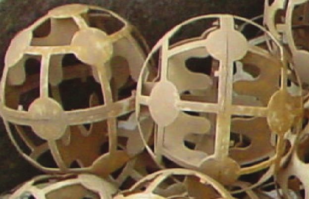
276 Z. Tong / Desalination and Water Treatment 110 (2018) 275–282
2. Materials and methods number is, and the higher effective energy consumption and
utilization is, accompanied by a stronger shearing effect on
2.1. Vortex reactor
the alum [5,6]. The vortex reactor is the core of the vortex
2.1.1. Construction features of the vortex reactor micro-coagulation process. According to Kolmogorov’s local
isotropic turbulence theory, in order to enhance the colli-
The vortex reactor is the core of micro-eddy flocculation sion efficiency among particles, the microscopic vortex scale
technique. Initially, the vortex reactor was designed to replace of the fluid must be effectively controlled. In engineering
the grid reactor and thus to solve the shortcomings of the lat- practice, the microscopic vortex scale could be controlled by
ter, such as installation inconvenience, congestion tendency, manipulating the aperture ratio and the hole diameter of the
and short life expectancy. Inspired by the idea of filling mate- vortex reactor in order to ensure a high coagulation reaction
rial applications during the sewage treatment process, the efficiency under a variety of conditions. Based on many years
vortex reactor is designed through repeated demonstration, of theoretical and practical studies, our research group has
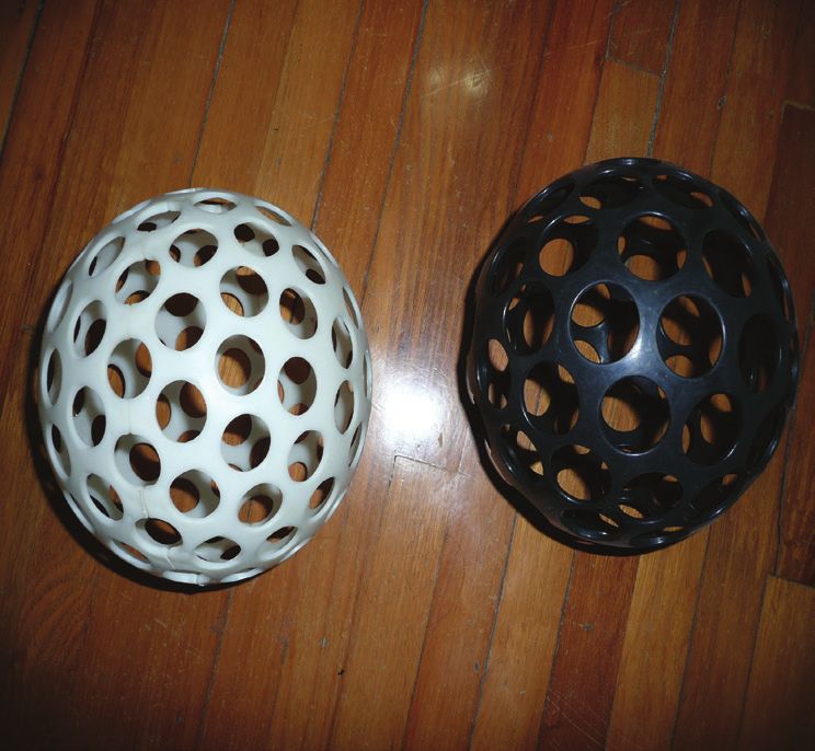
computing, and small-scale test, and the major structure fea- developed three types of vortex reactors to deal with differ-
tures of the vortex reactor are as follows [4]: ent treatment water quality as shown in Figs. 1, 2, and 3.
The main principle of the flocculation reaction realized
• hollow spherical structure, with its diameter determined by the vortex reactor is based on two aspects, micro-eddy
by technical requirement, and with both the inner and cohesion and three-dimensional contact flocculation. Fig. 4 is
outer surface dulled; a schematic view of the coagulation process [7,8].
• surface-opening holes, with corresponding pore size and
opening porosity determined by related technology;
• the utilization of acrylonitrile butadiene styrene (ABS) 2.2.1.1. Micro-eddy cohesion It can be known from coag-
plastic materials, with the bulk density slightly greater ulation dynamics that the power which promotes the par-
than that of water, and with wall thickness determined by ticle collisions in the water body is derived from the fluid
the structural strength.
2.1.2. Characteristics of the vortex reactor
The structural characteristics of the vortex reactor include
the following:
• Water micro-vortex flow is generated because of continu-
ous changing of flow velocity and flow direction through
holes, as well as persistent internal and external wall fric-
tion resistance;
• Lacking water flow direction; the vortex reactor can be
directly put into the water without clogging wall pores,
and it doesn’t need to be installed;
• The production of the vortex reactor can be carried out
in a large industrial scale. Because its structure is simple,
it is easy to produce and transport the produced prod-
ucts, the construction period of renovation project is rela- Fig. 1. HJTM1 type.
tively short, and the produced products could be widely
applied;
• The strength of the vortex reactor is good without toxic-
ity, and the reactor is corrosion-resistant, anti-aging, with
the usage life over several decades;
• The vortex reactor will rotate but not float on the surface
of water stream and will not be easily clogged.
2.2. Micro-eddy flocculation process
2.2.1. Micro-eddy flocculation principle
Currently, the mainstream control theory of the floccu-
lation process includes the velocity gradient theory and the
vortex theory. According to Kolmogorov’s micro-vortex scale
theory, during the flocculation process, the order of vortex
plays an important role, and its centrifugal inertia effect is the
dynamic cause of floc collisions. Also, the vortex of similar
size to those particles plays a dominant role in affecting the
motion of those particles. The smaller the mainstream spatial
scale is, the smaller the vortex scale and the vortex Reynolds Fig. 2. HJTM2 type.Z. Tong / Desalination and Water Treatment 110 (2018) 275–282 277
causes the radial movement of particles along the vortex
direction. As a result, destabilized colloids in the water body
are more likely to collide with one another in the presence of
micro-vortex actions, and corresponding condensation effi-
ciency is also dramatically enhanced. The flow rate could be
gradually reduced by controlling the opening ratio of vortex
reactors with different layers along water flow direction. As
a result, energy transferring process among vortexes of dif-
ferent sizes could also be reduced. Meanwhile, many smaller
vortexes are generated, and the viscous effect of water grad-
ually becomes larger, resulting in the loss of energy. With
the extension of residence time, water flow energy is grad-
ually reduced, accompanied by an increase in alum size,
associated condensed level, and the anti-shear capacity, all
of which facilitate the subsequent sinking process in the sed-
imentation tank.
Fig. 3. HJTM3 type.
2.2.1.2. Three-dimensional contact flocculation When a
large number of vortex reactors are installed in the coagu-
lation reaction zone, because the flow velocity within vortex
reactors is relatively small, a large number of larger-sized flocs
(alum) are accumulated in the vortex reactors or suspended
in the water body. The suspended flocs (or, more commonly
called as sludge) could absorb the destabilized colloids, and
this flocculation adsorption function is also known as con-
tact flocculation phenomenon. Compared with traditional
contact flocculation clarifier, the vortex reactor has higher
work efficiency. First, there is only one layer of suspended
flocs in the traditional clarifier, whereas the new technology
allows water to flow vertically through the vortex reactor
so that each vortex reactor has its own suspended flocs, the
total volume becomes larger, and three-dimensional contact
flocculation is generated. Second, the growth quality of flocs
Fig. 4. Coagulation process. is better within the internal part of the vortex reactor, and
flocs of larger size would be broken into smaller flocs with
motion. When water flows through many wall holes of the
good flocculation capacity (flocs of larger size would cause a
vortex reactor, some small vortexes and many tiny vor-
reduction of total surface area, and thus leads to an increase
texes are formed simultaneously. According to Kolmogor-
of absorption ability). Also, under the influence of micro-
ov’s local isotropic turbulence theory, vortexes of a variety
eddy process, low-density flocs would be broken down and
of sizes coexist in the turbulence. Large vortexes then pass
re-flocculate to form flocs with higher density, and to facili-
energy to small vortexes, which then further transport the
tate sediment separation process.
energy to vortexes with smaller sizes. Large vortexes tend
to cause particles to move as a whole without causing colli- In addition, the vortex reactor also plays other important
sions among particles, whereas tiny vortexes are not able to roles, such as preventing short water flow, promoting uni-
promote particle collisions. Only vortexes of similar size to form flow distribution, and increasing water flow velocity
nearby particles could cause collisions among particles. The gradient. In sum, the design of vortex reactor fully takes into
degree of turbulence could be controlled through choosing account various hydraulic intrinsic elements that might affect
vortex reactors with different surface-opening hole diame- the coagulation effect, and the optimum hydraulic conditions
ters and opening rates. Also, a combination of vortex reac- for coagulation are created so that the optimal effect of coag-
tors with different surface-opening hole diameters could ulation process could be realized.
promote the formation of vortexes of similar size to nearby
particles as much as possible, which is the key technique to
2.2.2. Characteristics of micro-eddy coagulation process
achieving excellent coagulation effect of the vortex reactor.
A large number of micro-vortex flows could effectively pro- 2.2.2.1. High coagulation efficiency Vortex micro-
mote the diffusion and collision processes of particles in the flocculation process creates highly efficient agglomeration
water body. On one hand, colloids from coagulant hydroly- and flocculation hydraulic conditions, and corresponding
sis could diffuse rapidly and collide completely with other coagulation efficiency is much superior to the conventional
colloids in the water body so that colloids from the water coagulation process or the grid coagulation process. The
body could be destabilized rapidly. On the other hand, the reaction time of vortex micro-flocculation process could be
large flow rate difference results in the relative movement shortened to 5–8 min, which also indicates that water pro-
of particles. Meanwhile, the centrifugal inertial force is gen- duction could be increased with small footprint and low
erated by the rotary action of the eddy current, which then investment compared with conventional processes.278 Z. Tong / Desalination and Water Treatment 110 (2018) 275–282
2.2.2.2. Excellent water outflow quality With the same Coagulants are diffused effectively due to micro-eddy
amount of coagulant dosage, the quality of flocs produced by current, which greatly increases coagulant utilization rate.
micro-vortex coagulation technique is much better than that Meanwhile, activities of flocs within the internal part of the
produced by traditional techniques; therefore, the settling vortex reactor are fully utilized so that the amount of coag-
capacity of the former is better that that of the later. ulants required in the micro-eddy flocculation technique is
significantly lower than that required in the traditional tech-
2.2.2.3. Adaptation ability of water quality and quantity nique [11,12].
Micro-eddy current coagulation is useful for the treatment of
polluted water with high turbidity. The micro-eddy current 2.2.2.6. Long-term service and easy maintenance The vor-
could facilitate rapid diffusion process of coagulants, mak- tex reactor is made of ABS plastic materials, and its service
ing them less susceptible to many impurities colloids in the life is up to several decades. Compared with grid coagu-
water body with very high turbidity. Even if coagulants are lation, wall holes of the vortex reactor are not likely to get
wrapped to form flocs, these flocs are easy to be broken down clogged, which is because the vortex reactor in the water is
to regain the flocculation capacity under the influence of in a semi-suspension state, and its rotation motion could
micro-vortex function [9,10]. enable floating debris that might clog wall holes to float on
Micro-vortex coagulation process is also useful for the the water surface and then be removed by hand. Even if the
treatment of polluted water with low turbidity. Even if the vortex reactor is clogged, it could be removed from the tank
number of collides in the water body is limited and the col- conveniently for a thorough clearage.
lision efficiency is reduced, suspended flocs could be effec-
tively maintained in the internal part of the vortex reactor,
and three-dimensional contact flocculation can efficiently 2.2.3. Requirements of micro-eddy coagulation technique
remove colloids from water body.
The core of micro-eddy flocculation technique is the
Low temperature is also unfavorable for the coagula-
vortex reactor, and the design of the vortex reactor could be
tion process of the micro-vortex reactors. As long as the
flexible according to water quality, structure shape, and other
appropriate coagulant is selected to overcome coagulant
characteristics. Specifically, requirements of micro-eddy
hydrolysis difficulties, and the micro-vortex cohesion and
coagulation technique include the following:
the three-dimensional contact flocculation is with high effi-
ciency, water treatment under low-temperature conditions is
• Keep water flowing vertically as much as possible so
no longer difficult.
that the upward or downward flow is perpendicular to
Micro-eddy flocculation technique has a strong adapt-
the horizontal plane. The vortex reactor must be placed
ability to the changes of water volume, which is because
in water with vertical flowing direction. Otherwise, floc
the hydraulic conditions of the coagulation process mainly
deposition will occur within the vortex reactor. The coag-
depend on the formation of eddy currents rather than the
ulation zone which is generated when the vortex reac-
macro velocity of the water flow. In contrast, the formation
tor is put into the upward flow is also called the upward
conditions of the coagulation process mainly depend on the
coagulation zone, whereas the coagulation zone which is
changes of water flow velocity (i.e., the opening ratio of the
generated when the vortex reactor is put into the down-
vortex reactor). In addition, a large number of active flocs are
ward flow is also called the downward coagulation zone.
accumulated in the micro-eddy coagulation zone, and they
• Both the upward coagulation zone and the downward
provide a buffering function of the changes of water quality
coagulation zone could be flexibly combined according to
and quantity. Also, these flocs would not be deposited, com-
specific circumstances, and their combination forms could
pacted, or discharged when water availability in the tank is
be “downward-upward,” “upward-downward,”“down-
limited, which makes the micro-eddy flocculation tank able
ward-upward-downward,”“upward-down-
to work intermittently.
ward-upward,”“downward-upward-downward-up-
2.2.2.4. Simple implementation Micro-eddy flocculation ward,” “upward-downward-upward-downward,” and
technique is suitable for either constructed new water plant so on. For each segment, water flow rate will be gradually
or modified traditional water plant, and it has no special reduced or remain unchanged, and water retention time
requirements for the tank size or the convergence process, in each segment should be no less than 5–8 min [13–16].
such as mixing and precipitation. The modification of the tra- • Vortex reactors with different surface-opening hole
ditional water plant is simple, as long as the old reaction tank diameters and opening ratios are used to control water
is removed, the existing facilities are appropriately segre- flow velocity through the hole. Theoretically, the flow
gated, and vortex reactor brackets are installed. When these velocity through the hole in the front region should be
conditions are met, the reactor could be put into use directly. slightly larger than the flow velocity through the hole in
the rear region. Meanwhile, reactor diameters of the front
2.2.2.5. Stable operation and low-dosage consumption Micro- region should be slightly smaller than reactor diameters
eddy flocculation technique no longer experiences difficulties of the rear region. However, under normal circumstances
that exist in the traditional technique regarding sludge clear- (e.g., when water quality is stable), in order to facilitate
age process within the clarifier tank. Flocs within the internal the construction and maintenance process, same vortex
part of the vortex reactor are kept for a long term, and floc reactors could also be used.
sludge outside the vortex reaction zone could be got rid of • Sludge clearage zone should be established reasonably
completely. Therefore, sludge clearage process could be sim- according to the principle that sludge clearage device
plified and the entire operation process could be more stable. should be installed at the bottom of tanks where sludgeZ. Tong / Desalination and Water Treatment 110 (2018) 275–282 279
deposition is more likely to be produced. Because the 3.1.2. Modification diagram of micro-eddy reaction
vortex reactor could also contain suspended sludge, the tank (unit: m)
sludge outside the vortex reactor should also be got rid
of completely. • The modification diagram of the grit chamber is shown in
Fig. 5 (front elevation) and Fig. 6 (side elevation).
3. Results and discussions • The modification diagram of the reaction tank is shown
in Fig. 7.
3.1. Engineering applications
3.1.1. Engineering background and process modification 3.1.3. Calculation of critical process parameters
The water treatment plant in Guangdong Province studied 3.1.3.1. Reaction time of micro-eddy current The height
was built in the 1980s with a design capacity of 100,000 ton/d. of the vortex reactor that could be installed in the orig-
The related technological process is raw water → grit chamber inal grit chamber is 2.4 m, and the total volume is
→ perforated swirling-flow tank → advection sedimentation 4.5 × 4.5 × 2.4 = 48.6 (m3).
tank → ordinary rapid filter → filtrated water tank. There The height of the vortex reactor that could be installed in
are two sets of structures in the water treatment plant, with the original reaction tank is as follows: the first grid is 3.0 m,
a design capacity of 50,000 ton/d for each set. As time goes the second grid is 2.7 m, the third grid is 2.5 m, the fourth to
by, the original design capacity of the water treatment plant sixteenth grid is 2.5 m, 2.3 m, 2.2 m, 2.1 m, 2.0 m, 1.9 m, 1.8 m,
could not meet the increasing needs for local rapid develop- 1.7 m, 1.5 m, 1.4 m, 1.3 m, 1.1 m, and 1.0 m, respectively
ment. To solve the supply/demand contradiction, local gov-
ernment asks the water plant to expand its production scale
to satisfy daily water supply requirement of 18 million ton.
Because the construction of a new water treatment plant is
not only time-consuming but also requires large investments,
local government decides to have the old water treatment
plant expanded or modified. Due to the constraint of geologi-
cal locations of the old plant, the expansion of a new group of
structures is unlikely, and the only hope is to achieve the goal
of increasing water storage capacity through plant modifica-
tion and technological innovation. The company once consid- vortex reactors
ered the application of grid technique as one way of techno-
logical innovation, but had to give it up due to high precision
requirements and large investment expenses during the con-
struction processes. Taking into account technical, economic,
duration, and other important factors, the water treatment
plant finally decides to adopt the micro-eddy flocculation
technique developed by East China Jiaotong University. The
original structures of the water treatment plant remain intact
except for some minor modifications [17]:
• Both the grit chamber and the reaction cell are trans- Fig. 5. Front elevation.
formed into the micro-eddy reaction tank. In order to
enhance water production, the reaction time can be
extended around 0.8 min when the grit chamber is trans-
formed into the micro-eddy reaction tank (water inflow
part is approximately handled) to ensure the coagulation
reaction effect.
• HJTM1 and HJTM2 type vortex reactors are installed in
the original reaction tank, for which HJTM2 type reactors
are installed in 1–3 cells, both HJTM1 and HJTM2 type vortex reactors
reactors are installed in 4–9 cells, and HJTM1 vortex reac-
tors are installed in 10–16 cells.
• After water production is enhanced, overflow is likely to
occur in 2–3 cells of the original reaction tank; therefore,
part of the cell body should be increased 0.5 m in order
inlet baffle
to increase the tank volume. Furthermore, the size of sub-
merged orifice is expanded for the outflow area of the
sedimentation tank. In contrast, the filter tank remains
unchanged (there were three sets of filter tanks in the origi-
nal design, but only two sets were used. Therefore, all three
sets have been used during this modification process). Fig. 6. Side elevation.280 Z. Tong / Desalination and Water Treatment 110 (2018) 275–282
come from grit chamber
flow to sedimentation tank the cell body increased 0.5m
3.96 4.26
3.65 3.75 3.86
3.35 3.55
3.15 3.25
1.65 1.55 1.36 1.26
2.15 1.95 1.85 1.75
Fig. 7. The modification diagrammatic sketch of the reaction tank.
It can be concluded that the total height is 31.1 m, and the Because the micro-vortex reaction could improve the floc-
total volume is 1.7 × 1.7 × 31.1 × 2 = 179.8 (m3). culation effect, the sedimentation effect could be guaranteed.
The total volume of each micro-eddy reaction zone is
48.6 + 179.8 = 228.4 (m3). 3.1.4. Results
If the design capacity is set as 70,000 tons/d, the reaction
time of micro-eddy current is (228.4 ÷ 70,000) × (24 × 60) = The entire transformation process is simple and convenient
4.7 (min). to carry out with short construction period (approximately
According to the design requirements of micro-eddy cur- 20 d). After 2 m trial operation was conducted, the effect is
rent reaction, the reaction time is generally between 5 and satisfactory. Overall, after the micro-eddy reaction technique
8 min, and the total volume of original grit chamber and reac- is applied, the entire reaction process is complete, and water
tion tank is (4.5 × 4.5 × 4.0) + (1.7 × 6 × 1.7 × 6 × 4.0) = 497.2 (m3). quality is greatly improved compared with the original pro-
The reaction time of non-micro-eddy current is (497.2 – 2 cess. The specific performance includes the following: First,
28.4) ÷ (70,000) × (24 × 60) = 5.53 (min). condensed alum in the reaction tank is clear with obvious par-
Therefore, the total reaction time is 4.7 + 5.53 = 10.23 (min). ticles and good settling characteristics. In contrast, condensed
Based on previous experience, the reaction effect could alum could only be found in the sedimentation tank before
be guaranteed. transformation. Second, the muddy water area of the sedimen-
tation tank is dramatically reduced. Water from 2/3 of the sed-
3.1.3.2. Velocity of micro-eddy current reaction zone The imentation tank before transformation is yellowish, whereas
velocity of micro-eddy current reaction zone should be con- water from 2/3 of the sedimentation tank after transformation
trolled between 60 and 80 m/h. Otherwise, gland facilities is greenish, thus indicating that water quality is significantly
should be installed in the upwelling area to prevent the vor- improved. Third, the filter working cycle is extended, and the
tex reactor from floating. backwash time is shortened (the source of backwash water is
After the grit chamber is transformed into micro-eddy the water tower). Backwash water consumption is reduced by
reaction tank, the upwelling velocity is (70,000 ÷ 24) ÷ approximately 30%, indicating that the turbidity of water that
(4.5 × 4.5) = 144 (m/h). needs to be treated is reduced, and alum flocculation qual-
Therefore, gland facilities are needed after the transfor- ity is enhanced. Fourth, water turbidity before filtration pro-
mation of the grit chamber. cess remains at about 3 NTU, but is reduced to 1 NTU or less
After the reaction tank is transformed into micro-eddy after filtration process (for most cases water turbidity is below
reaction tank, the upwelling velocity is (70,000 ÷ 24) ÷ 0.5 NTU). Table 1 compares some parameters before and after
(2 × 1.7 × 1.7) = 505 (m/h). the modification of the water treatment plant.
Therefore, gland facilities are also needed after the trans- An analysis based on Table 1 shows that after the applica-
formation of the old reaction tank. tion of the vortex reactor, the backwash rinse of the filter tank
3.1.3.3. Average velocity gradient G value and GT value is clean and thorough, the filtering effect is improved, the fil-
G =[(γ × h) ÷ (60 × μ × T)]1/2(T = 15°C) Based on on-site esti- tration cycle is extended, the rinsing frequency is reduced,
mation, water loss of the vortex reactor per meter along water and the amount of backwash water required is reduced.
flow direction is about 7 mm. Therefore, water loss though Table 2 displays a comparison of the working status of the
the entire vortex reactor is 7 × (31.1 + 2.4) ÷ 1,000 ≈ 0.24 (m). filter tank before and after the transformation of the reaction
With data input, G = [(1,000 × 0.24) ÷ (60 × 0.1165 × 10–3 × tank. It can be seen from the data that the reduced amount
7.95)]1/2 ≈ 65.7(s–1) of backwash water each time for each filter cell is 100 m3,
GT = 65.7 × 7.95 × 60 = 3.15 × 10⁴. and nearly 30% of the backwash water is saved. Or, in other
It matches classic coagulation control indicator. words, before the transformation, the amount of rinse water
throughout the entire year for each filter cell is 811,920 ton,
3.1.3.4. Settling time Overall water production is but is reduced to 555,120 ton after transformation, so the
enhanced after the transformation. The settling time is short- amount of water saved annually is 256,800 ton. If the cost of
ened to (91.8 × 12.0 × 3.2) ÷ (70,000 ÷ 24) = 1.21 (h). water is 0.5 RMB per ton, then 128,400 RMB can be savedZ. Tong / Desalination and Water Treatment 110 (2018) 275–282 281
Table 1
The change of some parameters before and after modification
Comparison project Before modification After modification Remarks
Water production, m3/d 50,000 70,000
Dosage input (AlCl3), mg/L 12 10
Flocculation reaction time, min 12 8
Retention time in the sedimentation tank, h 1.90 1.21
Alum status Unclear Clear particles Within the reaction tank
Water turbidity before filtration, NTU 10 3
Filtration rate, m/h 8 10.8
Filter cycle, h 22 34
Backwash strength, L/s.m2 13 13 Provided by water tower
Backwash time, min 9 6
Backwash effect Incomplete Clean and complete
Amount of backwash water within each cell, m3/d 340 240 Water production as
50,000 ton/d
Water turbidity after filtration, NTU 1 0.5
Table 2
Filter flushing before versus after modification
Comparison project Before modification After modification Saved water amount Saved percentage
The amount of backwash water per cell, m 3
340 240 100 29.4%
Filter cycle, h 22 34
Annual times 398 257
The amount of backwash water per cell 135,320 61,680 73,640 54.4%
each year
The number of filter cells 6 9
The amount of backwash water for the 811,920 555,120 256,800 31.6%
entire filter tank
annually. As the source of backwash water is the water tower between the transformation design and trial commissioning is
and the amount of needed backwash water is reduced, certain less than a month, but the outcome is obvious. It has operated
amount of power cost is saved as well. According to a prelim- smoothly and stably for several years, with the amount of fin-
inary estimation, the transformation cost could be regained ished water remaining below 0.5 NTU.
within 4 or 5 years after the application of the vortex reactor. Both theory and practice have proved that after the appli-
cation of the micro-eddy flocculation technique, the hydrau-
4. Conclusion lic conditions of the system have been greatly improved, the
flocculation reaction efficiency of the water purification pro-
Vortex reactor technology is easy to carry out during the cess has been enhanced, the flocculation time has been short-
transformation processes. Although the coagulation effect is ened, the amount of dosage required has been reduced, and
enhanced with the application of the vortex reactor, the desta- the quality of purified water has been improved. Meanwhile,
bilization effect is realized under the premise that dosage a large amount of backwash water has been saved, and the
amount is appropriate. Because the flow volume is increased anti-change adaptation capacity of the entire water purifica-
by 20%, the retention time in the reaction and sedimenta- tion system has been greatly improved. The successful trans-
tion tank is greatly shortened, and the filtering velocity is formation of this water treatment plant fully demonstrates
enhanced, more stringent requirements regarding the opera- that the micro-eddy flocculation technique is both feasible
tion and management process are needed, especially dosage and effective. Also, with a high practical value regarding
amount should be controlled more cautiously. Also, the coag- water quality and social benefits, application and promotion
ulation effect of the vortex reactor could be more obvious if the of this new technique in practice is promising.
automatic dosage addition process is realized. Observations
during the debugging process show that the micro-eddy
Acknowledgments
reaction can achieve the best results under a long and stable
flow operation condition. This is because with such a steady This work was supported by the National Natural
flow operation condition, the sludge inside the reactor will Sciences Foundation of China (No. 51268012). The author
gradually accumulate and the flocculation (adsorption) effect wishes to thank International Science Editing for their expert
could be optimized. For the studied water plant, the time span help in editing the manuscript.282 Z. Tong / Desalination and Water Treatment 110 (2018) 275–282
References [10] N. Hashemi, Recognizing the potential of sustainable use of
pasture resources in south Khorasan province with approach of
[1] X. Yan, Water Supply Engineering, 4th ed., China Building carrying capacity, Environ. Ecosyst. Sci., 1 (2017) 9–12.
Industry Press, Beijing, 2011. [11] N.D. Tzoupanos, A.I. Zouboulis, Novel inorganic-organic
[2] Z. Yuan, H. Zheng, X. Shu, Advancement of coagulation science composite coagulants based on aluminium, Desal. Wat. Treat.,
and technology, J. Chongqing Univ., (Natural Science Edition), 13 (2014) 340–347.
24 (2011) 143–146. [12] O. Adugna, D. Alemu, Evaluation of brush wood with stone
[3] N. Ebrahimi, M. Gharibreza, M. Hosseini, M.A. Ashraf, check dam on gully rehabilitation, J. CleanWAS, 1 (2017) 10–13.
Experimental study on the impact of vegetation coverage on [13] D.J. Wu, X.W. Wang, C.H. Xiu, Study on kinetic cause of
flow roughness coefficient and trapping of sediment, Geol. turbulence flocculation, J. Shandong Inst. Archit. Eng., 15 (2000)
Ecol. Landscapes, 1 (2017) 167–172. 1–4.
[4] Z. Tong, F. Hu, Development and application of integrated [14] H.L. Fu, X.J. Liu, Research on the phenomenon of Chinese
vortex-grid clarification process, China Water Wastewater, 26 residents’ spiritual contagion for the reuse of recycled water
(2012) 63–68. based on SC-IAT, Water, 9 (2017) 846.
[5] S. Wang, Coagulation-low ripple precipitation water treatment [15] Z.L. Liu, China’s plans and policies for reducing CO2 emission
technology, Water Wastewater Technol. Inf., 1 (2010) 7–12. from biomass-fired power plants: modeling and economic
[6] W. Gao, M.R.R. Kanna, E. Suresh, M.R. Farahani, Calculating of study, Energy Sources Part B, 12 (2017) 1001–1006.
degree-based topological indices of nanostructures, Geol. Ecol. [16] G. Farajollahi, M.R. Delavar, Assessing accident hotspots by
Landscapes, 1 (2017) 173–183. using volunteered geographic information, J. CleanWAS, 1
[7] Z. Tong, Study on the technology of vortex coagulation and its (2017) 14–17.
application in water plant of DongFeng motor corporation, J. [17] Z.G. Tong, P.P. Lu, Application of micro-vortex coagulation
Water Supply Res. Technol. AQUA, 61 (2012) 253–257. process in rebuilding engineering of Liling Railway Water
[8] S.M. Hejazi, F. Lotfi, H. Fashandi, A. Alirezazadeh, Serishm: Plant, China Water Wastewater, 28 (2012) 79–81.
an eco-friendly and biodegradable flame retardant for fabrics,
Environ. Ecosyst. Sci., 1 (2017) 5–8.
[9] W.P. Cheng, J.N. Chang, P.H. Chen, Turbidity fluctuation as a
measure of floc size in a coagulation pilot study, Desal. Wat.
Treat., 30 (2011) 98–104.You can also read