Minimized Total Harmonic Distortion of a Multi-level Inverter of a Wind Power Conversion Chain Synchronized to the Grid-LCL Filter Optimization ...
←
→
Page content transcription
If your browser does not render page correctly, please read the page content below
ORIGINAL ARTICLE
                                                                                                                                        Electrica 2022; 22(1): 27-40

Minimized Total Harmonic Distortion of a Multi-level Inverter of a
Wind Power Conversion Chain Synchronized to the Grid-LCL Filter
Optimization and Third Harmonic Cancellation
Wijdane El Maataoui1 , Soukaina El Daoudi2 , Loubna Lazrak2 , Mustapha Mabrouki1
Laboratory of Industrial Engineering, Faculty of Sciences and Technology, Sultan Moulay Slimane University, Beni-Mellal, Morocco
1

Laboratory of Automatic, Energy Conversion and Microelectronics, Faculty of Sciences and Technology, Sultan Moulay Slimane University, Beni-Mellal, Morocco
2

Cite this article as: W. El Maataoui, S. El Daoudi, L. Lazrak, and M. Mabrouki, “Minimized total harmonic distortion of a multi-level inverter of a wind power
conversion chain synchronized to the grid-LCL filter optimization and third harmonic cancellation,” Electrica, 22(1), 27-40, Jan. 2022.

ABSTRACT

In order to improve the wind power conversion chain performance on the grid side, this work proposes the use of multi-level inverter and a fairly high switching
frequency for an optimized LCL filter, while respecting the grid connection conditions. The method used consists of reducing the total harmonic distortion and
adjusting filter parameters to cancel the third order harmonic. For grid-side chain control, two cascaded current and voltage control loops are used to generate the
inverter pulse width modulation. To ensure synchronization even in the presence of grid faults or unbalance, a phase-locked loop (PLL) circuit with a multi-variable
band-pass filter (MVBPF) is adopted. To validate the theoretical study, simulations are performed for a 300 W chain with a two-level, three-level, and five-level inverter
using three different filters. A comparative study of the results shows that the use of the five-level inverter with the optimized filter effectively reduces ripples while
meeting grid coupling conditions.
Index Terms—LCL filter, multi-level inverters, multi-variable band-pass filter (MVBPF), phase-locked loop (PLL), sinusoidal pulse width modulation (SPWM), total
harmonic distortion (THD), wind turbine conversion chain.

                                                      I. INTRODUCTION

                                                      According to the “World Energy Outlook 2015” study by the International Energy Agency (IEA), about
                                                      67% of the world’s electricity is generated from fossil fuels which constitute the main source of elec-
                                                      tricity produced globally [1]. However, the negative environmental impacts of fuel-based electric-
                                                      ity generation, climate change, depletion of fossil fuel reserves, and price fluctuations require the
                                                      increased use of renewable energy for electricity supply worldwide [2, 3]. The use of wind energy
                                                      for power generation was developed in the early 20th century, making it the most promising clean
                                                      and sustainable energy source [4]. Globally, wind energy has been growing at a rate of 30% per year
                                                      for the past decade [5]. According to the Global Wind Energy Council (GWEC), 2020 was the best
                                                      year in history for the global wind industry, with 93 GW of newly installed capacity [6]. The principle
Corresponding Author:                                 of the wind turbine generator is to use the kinetic energy of wind to drive the rotor shaft and thus
Wijdane El Maataoui
                                                      transform it into mechanical energy, which is converted into electrical energy by means of an elec-
E-mail:                                               tromagnetic generator [7]. Several types of electrical machines can be inserted in the wind turbine
elmaataoui.wijdane@gmail.com
                                                      conversion chain, adjusted to the chosen installation control. The specifications for wind generators
Received: July 14, 2021                               vary according to the type and geometric dimensions of the wind turbine, where the synchronous
Revised: October 2, 2021                              machine can be used in the case of direct drive [8]. The electrical energy produced by the wind
Accepted: October 8, 2021                             turbine can be stored by accumulators, distributed through a power grid, or absorbed by isolated
                                                      loads. Static converters such as inverters are an important part of the electrical energy conversion
Available Online Date: November 17, 2021
                                                      chain and have a strong influence on the quality of the produced energy. In recent years, the use
DOI: 10.5152/electrica.2021.21086
                                                      of multi-level converters for power electronic applications has seen increasing demanded due to
                                                      their many advantages, especially in the medium and high-power range [9-11]. The control of the
                                                      inverter switches directly impacts the total harmonic distortion (THD) and the switching losses of
Content of this journal is licensed                   the inverter [12]. Among the techniques used is the sinusoidal pulse width modulation (SPWM).
under a Creative Commons                              This method has a simple structure to manipulate with a very low computation time, while pushing
Attribution-NonCommercial 4.0
International License.

                                                                                   27
Electrica 2022; 22(1): 27-40
                                                   El Maataoui et al. Wind Power Conversion Chain

the harmonics to high frequencies, which makes filtering much easier              internal current regulation loop, an external voltage regulation loop,
[13]. The insertion of a filter satisfies the conditions of coupling with         and an FMVPB-dq-PLL synchronization loop.
the grid, and the most commonly employed filters are L, LC, and LCL.
The major disadvantage of the L filter is the large value of the induc-           A. Two-level Inverter
tance which leads to high voltage drops [14]. However, the use of an LC           Fig. 1 shows the topology of the two-level inverter, which is com-
filter is not recommended for renewable energy conversion systems                 posed of three arms with two electronic switches, with antiparallel
due to the direct connection instability of the capacitor in parallel with        protection diodes placed in each of them to ensure freewheeling.
the grid [15]. The LCL structure presents an alternative that reduces its         The switch type used depends on the inverter power and the switch-
parameter dimensions and increases attenuation. However, the disad-               ing frequency. In most applications, IGBT transistors with antiparal-
vantage of this filter design is the resonance, which can be reduced              lel diodes are employed since they have high efficiency and good
by inserting a resistor in parallel or in series with the capacitor and           robustness. The inverter is powered by a DC voltage source, either
inductors [16]. Nonetheless, a connection with the grid requires good             from three-phase diode rectifier or from batteries [10].
synchronization, where the amplitude, frequency, and phase angle
of the grid voltage are the three essential elements to ensure it. The            The triangle sine pulse width modulation (SPWM) is realized by
phase-locked loop (PLL) is widely used to achieve the aforementioned              comparing a low-frequency modulating wave (reference voltage) to
components [17]. Several synchronization circuit structures are used in           a high-frequency triangular carrier wave. The switching times are
the literature such as zero-crossing detection (dq-PLL), direct system            determined by the intersection points between the carrier and the
extraction of voltages with dq-PLL (PSD-dq-PLL), and filtering of mea-            modulating waves.
sured voltages with dq-PLL (FMVPB-dq-PLL) [18]; the interest of this
last structure is to ensure a good synchronization with the grid even in          B. LCL Filter Design
the presence of faults or unbalance of the latter [19, 20].                       The LCL filter remains the right choice compared to the other filters
                                                                                  mentioned in the literature, since it represents an attenuation of 60
In order to improve the wind conversion chain, [21] proposed a com-               dB/decade and its resonance is independent of the grid impedance.
parative study of various methods to optimize the LCL filter. However
those techniques have many disadvantages such as complex design                   This filter can be modeled by three identical single-phase electrical
and non-fulfillment of the imposed performance indexes. Furthermore,              diagrams, presented in Fig. 2.
very few research studies have been done in analyzing performance
of the conversion chain while using a multi-level inverter and an opti-           To solve the resonance problem produced by LCL filter at its cutoff
mized LCL filter at the same time.                                                frequency, it is necessary to insert a real damping resistor in the pas-
Thus, the main contributions of the present work are about design-                sive case and a virtual damping resistor in the active case.
ing an optimized LCL filter, PLL synchronization on the grid side with
multi-variable band pass filter (FMVPB-dq-PLL), and the use of a                  The single-phase modeling of the LCL filter can be represented as
multi-level inverter, especially the three-level and five-level inverters.        follows:
A consistent comparative study has been made with three inverter
topologies and three designs of the LCL filter.                                          i1  i 2  i c

The method of optimizing the LCL filter parameters is suggested to                 i R i  sLi  i1  v c
                                                                                    v

improve the output magnitudes by cancelling the third order har-


                                                                                  v c  R g  sLg i 2  v g . (1)

monic. The use of the five-level inverter with the optimized LCL filter            v  i  1 R
and FMVPB-dq-PLL allows a great THD mitigation, and a remarkable                   c c  sC            c


reduction of the installation cost while meeting the requirements of
grid connection.
                                                                                  In the low-frequency range, the LCL filter behaves like an L-filter, thus
The paper is structured as follows: the architecture of the power con-            the LCL filter can be remodeled by neglecting the filtering capacity
version chain with the two-level inverter, the sizing of the LCL filter,          C:
the closed-loop control, as well as the FMVPB-dq-PLL synchronization
are represented in Section 2. Sections 3 and 4 are devoted to the con-
                                                                                          i1  i 2  i

version chain with the three-level and five-level inverters respectively,          v i  R i  sLi  i1  v c . (2)
and their balancing loops are also presented. Sections 5 and 6 discuss
the methods adopted to optimize the filter and to cancel the third
                                                                                  v c  R g  sLg i 2  v g
order harmonic. The simulation results are presented and discussed in
Section 7, before closing with a general conclusion in Section 8.                 Considering the output voltage as an ideal source (vg = 0), the expres-
                                                                                  sion of the transfer function of the filter is presented as follows:
II. STRUCTURE OF THE ENERGY CONVERSION CHAIN WITH
THE USUAL TWO-LEVEL INVERTER                                                       i (s )             1
                                                                                                                  . (3)

                                                                                  v i ( s ) R i  R g  s Li  L g
Fig. 1 shows the schematic diagram of the power conversion chain
on the grid side. It consists of a two-level inverter, an LCL filter, an          The impedance and base capacitance are defined as [22]:

                                                                             28
Electrica 2022; 22(1): 27-40
                                                El Maataoui et al. Wind Power Conversion Chain

Fig. 1. Schematic diagram of the power conversion chain on the grid side with the two-level inverter.

                                                                                 E 2
                                                                             Zb  n
                                                                                  Sn
                                                                                      (4)
                                                                            C  1
                                                                             b Z
                                                                                    b

                                                                            where Sn is the nominal apparent power and En is the nominal
                                                                            voltage.

                                                                            Assuming that the maximum variation of the power factor from the
                                                                            grid side is equal to 10%, we get the following expression:

Fig. 2. Representation of the single-phase electrical circuit of the                    Sn
LCL filter with the passive damping resistor.                               C  0.1*           . (5)
                                                                                       E n2

                                                                       29
Electrica 2022; 22(1): 27-40
El Maataoui et al. Wind Power Conversion Chain
TABLE I. LCL1 FILTER PARAMETERS WITH 5 KHZ AND 10 KHZ SWITCHING FREQUENCIES
Ri (Ω) Li (H) Rc (Ω) C (μF) Rg (Ω) Lg (H)
5 kHz 10 kHz 5 kHz 10 kHz
LCL1 200 2.07 1.04 160.51 0.66 8 9.21*10–3 2.30*10–3
The maximum current ripple at the output of the inverter is given To calculate the inductance Lg, an attenuation factor of ka = 20% is
by [22]: imposed.
2Vdc The Rc resistor in series with the capacitor attenuates a part of the
Imax
(1
m )mTsw (6)
3Li fluctuations at the switching frequency to avoid the resonance
peak [22]:
where m is the modulation factor of the inverter and Tsw is the switch-
ing period. 1
Rc (11)
3
res C
For m = 0.5, the maximum peak-to-peak ripple of the current is:
Vdc Li
L g
Imax
(7)
6f sw Li with res
and 10fg < fres < 0.5fsw
Li L g C
where fg is the grid frequency and fsw is the switching frequency.
where Li is the inductance on the inverter side, fsw is the switching
frequency, and vdc is the DC voltage.
Table I shows the filter parameters calculated for the frequencies
A ripple of 1% of the nominal current is chosen to the design the 5 kHz and 10 kHz; according to the results, it is preferable to work
filter parameters: with the 10 kHz switching frequency to gain on filtering.
Imax
0.01* Imax (8) C. Control Strategy
The control method used in this paper consists of two cascaded con-
Pn 2 trol loops; the first one concerns the voltage control loop and the
with Imax = second one presents the current control from the first loop.
3E ph
where Pn is the active power and Eph is the phase voltage. 1) Internal current regulation loop
The current control loops along the d-axis and q-axis have the same
Therefore, the expression of the inductance on the inverter side is: dynamics; therefore, the setting of the controller parameters is done
only for the d-axis. Fig. 3 shows the internal current control loop.
Vdc
Li . (9)
6f sw
Imax The loop consists of PI regulator, control block, sampling block,
transfer functions of the inverter, and the filter. The expressions that
The formula of the inductance on the grid side is written in the fol- define each block are expressed afterward.
lowing form [22]:
The transfer function of the PI corrector is:
1
1
K
sK P
k a2 HPI (s ) I . (12)
Lg (10)
s
2
C
sw
The control of the system is characterized by a transfer function of
where ka is the attenuation factor and ωsw is the switching pulsation. the first order, which is written in the following form:
Fig. 3. Current control loop.
30
Electrica 2022; 22(1): 27-40
El Maataoui et al. Wind Power Conversion Chain
1 is the response time. By identification, KP and KI can be expressed as
HControl (s ) (13) follows:
1
sT s
where Ts =
1
is the sampling time.
K I LT n2
. (20)
fs
K P 2nLT
RT
The transfer function of the inverter is formulated as follows:
1 2) External loop of the voltage regulation
H inverter (s ) (14) The DC voltage loop, shown in Fig. 4, provides the reference current
1
sT sw
along the d-axis. It consists of PI control block, the closed-loop trans-
where Tsw is the switching period. fer function of the internal current loop, and the differential equation
describing the voltage dynamics.
The LCL filter can be expressed by the following transfer function:
The DC intermediate circuit of the inverter is modeled as follows:
1 Ke
Hfilter (s ) (15)
sLT
RT 1
sTe dv dc
i dc C dc
i inv . (21)
1 L dt
where LT = Li + Lg, RT = Ri + Rg, K e = , and Te = T .
RT RT The active and reactive power exchanged between the inverter and
The system has a sampling delay which is expressed in the f ollowing the grid in the synchronous reference frame (d–q) are:
form:
3
H sampling
1
. (16)
P 2 v d i d
v q i q v dc i dc
1
s * 0.5Ts . (22)
3
Considering the control, inverter, and sampling transfer functions as
Q v q id v d iq
2
delays, the open-loop transfer function of the internal current con-
trol loop is as follows: Assuming that the d-axis of the rotating marker is aligned with the
AC voltage of the grid (vq = 0), the active and reactive power will be
K e
K I
sK P
H c ,OL . (17) expressed as follows:
s
1
sTe
3
The expression for the closed-loop transfer function of the current P 2 v d i d
control can be written as follows:
. (23)
Q
3 v i
d q
K e Te
K I
sK P
2
H c ,CL . (18)
1
K e K P K K
s2
s
e I
Te Te According to (21), (22), and (23), the dynamics of the DC voltage will
be articulated as:
In order to determine the parameters KP and KI of the associated PI
controller, the closed-loop transfer function is rewritten as a second dv dc 3 v d
C dc i d
i inv . (24)
order equation: dt 2 v dc
2
n s
n2
H (s ) (19) The closed-loop transfer function of the current can be written in the
s 2
2
n s
n2 following form:
where ωn is the natural pulsation and ξ is the damping factor. For 1 0.5T
1
H c ,CL
2 3 2sT
1
sT
1 2sT
1
, an equivalent value of n
is associated with tr which
2 tr
Fig. 4. Voltage control loop.
31
Electrica 2022; 22(1): 27-40
El Maataoui et al. Wind Power Conversion Chain
0.5T
1 reliable frequency and phase detection will be achieved even if volt-
H c ,CL (25) age imbalances and distortions are p roduced. The schematic dia-
sTeq
1
gram of the dq-PLL + MVBPF is shown in Fig. 5.
with Teq = 2T∑ and T∑ = 2Ts, The filter, called the multi-variable filter can extract directly the fun-
damental signals (voltage or current) in the αβ axis without leading
where Ts is the sampling period. to either phase shift or change in voltage amplitude. However, it can
also be used to reduce the direct and inverse harmonic components
Therefore, the open-loop transfer function of the DC voltage in a of input signals.
simplified way is as follows:
The equivalent transfer function of the integration in the synchro-
1
sTi _ dc 1 3 vd nous reference frame is expressed by [20]:
H dc ,OL K p _ dc . (26)
sTi _ dc sTeq
1 2 sC dc v dc
v xy (t ) e j
t e j
t u xy (t )dt . (28)
Applying the criterion of optimal symmetry, the parameters of the PI
After Laplace transformation, the transfer function can be expressed
controller could be written as :
as follows:
2v dc C dc V
f (s ) (s
K f )
j c
=K p _ dc = ; Ti _ dc a2Teq and a=3. H (s ) Kf (29)
3aTeqv d V
(s ) (s
K f )2
c 2
Moreover, in steady state vd = vdc: Kf
c
V f (s )
s V (s ) V f (s ) s V
f (s )
(30)
2C dc C dc V (s )
K f V (s ) V (s )
c V (s )
K p _ dc 3aT 6aT
s s
f
f f
eq s
Then
. (27)
K C dc with:
I _ dc
72a2Ts 2
c : Cut
off pulse
C. dq-Phase-Locked Loop and Multi-variable Band-Pass Filter K f : Dynamic gain
Synchronization V
: Input voltage
This PLL strategy is designed with a Multi-Variable Band-Pass Filter
block (MVBPF) and the usual dq-PLL. By applying this structure, V
f : Output voltage
Fig. 5. dq-PLL + MVBPF synchronization.
32
Electrica 2022; 22(1): 27-40
                                                  El Maataoui et al. Wind Power Conversion Chain

III. CHAIN STRUCTURE WITH THE THREE-LEVEL NPC INVERTER                           Sine pulse width modulation (SPWM), which is used to determine
                                                                                 in real time the closing and opening states of the switches, consists
The power conversion chain with the three-level inverter, shown                  of using the intersections of a reference wave, generally sinusoi-
in Fig. 6, consists of a three-level inverter, an LCL filter, an internal        dal, with a triangular signal (known as the carrier). Two parameters
current regulation loop, an external voltage regulation loop, and a              characterize this control: the modulation rate and the modulation
dq-PLL synchronization loop, plus an MVBPF with a balancing loop.                index [10].
A. NPC Three-Level Inverter                                                      B. Balancing Loop
The main circuit of the three-phase three-level NPC inverter is shown            The NPC inverter has an inherent problem of asymmetrical voltages
in Fig. 6. This topology consists of three arms each with four power             across the DC link capacitors, a disadvantage which occurs due to
switches with two antiparallel diodes. Each phase shares a common                the irregular charge/discharge and non-identical properties of the
DC bus, subdivided by two capacitors providing the neutral point N.              DC bus capacitors supplied by the manufacturer. For the three-level
The NPC reduces both current and voltage harmonics at the outputs                inverter, and in order to solve the above-mentioned anomaly, a bal-
[23]. The input DC bus of the three-level inverter is composed of two                                                 V
                                                                                 ancing loop is required by putting dc  = V=c 1 Vc 2 .
capacitors in series (C1 and C2), forming a midpoint that allows the                                                   2
inverter to access an additional voltage level compared to the con-              The modulation signals are appropriately selected to generate
ventional two-level inverter.                                                    the balanced AC voltage at the output terminals of the inverter.

 Fig. 6. Schematic diagram of the power conversion chain on the grid side with the three-level NPC inverter.

                                                                            33
Electrica 2022; 22(1): 27-40
El Maataoui et al. Wind Power Conversion Chain
This balancing of the DC voltage of the inverter reduces the har- VI. CONSTRAINT ON THE THIRD ORDER HARMONIC
monic content and maintains the voltage stability in the neutral
point [24]. According to Fig. 8 and 9 from simulation results section, the third
order harmonic is preponderant. In order to eliminate this constraint,
IV. CHAIN STRUCTURE WITH THE FIVE-LEVEL INVERTER it is necessary to resize the filter by considering the star–delta con-
version method. This latter consists of defining the filter parameters
The difference between the power conversion chain with the by cancelling the equivalent impedance for a pulse equal to three
three-level NPC inverter and that with the five-level inverter is times the fundamental pulse. Fig. 10 shows the principal star con-
the balancing loop. The three-level NPC inverter adopts a single figuration of the LCL filter.
balancing loop, while the five-level inverter has three balancing
loops. In order to determine the elements of the LCL filter presented ear-
lier, an equivalent triangle configuration is proposed (Fig. 11).
A. Five-level Inverter
Multi-level inverters have been the subject of several researches in
recent years and are now widely used in large and medium power The impedances of the LCL filter in star configuration are presented
conversion chains. These inverters are capable of minimizing total as follows:
harmonic distortion and surge stress in the system by spreading
the switching over multiple semiconductors [11]. Among the many z R
jL
multi-level topologies, the five-level blocking diode inverter is the a i i
most frequently used, consisting of three symmetrical arms each
z b R g
jLg . (31)
consisting of eight bidirectional switches in series with antiparal-
z R
1
lel diodes. These switches must not be opened or closed simul- c C
jC
taneously, in order to avoid short-circuiting the DC source at the
inverter’s input. The number of blocking diodes is six per arm, By making the star–delta conversion equality of the two previous
ensuring the application of different voltage levels at the output. circuits, the expressions of the impedances of the delta circuit are
Each arm is connected to the DC supply Vdc which is divided into then written as:
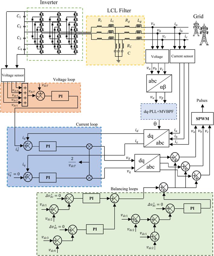
four equal parts using four capacitors (Fig. 7). This inverter is called
five-level because it delivers five levels of the single output voltage N N N
Vdc Vdc Vdc Vdc =ZA = ; ZB ; ZC = (32)
, , 0 , , . z a z b z c
2 4 4 2
The POD-PWM phase opposition technique uses four carrier signals with
to generate switching pulses. The carrier waves are in phase with a
level above zero reference and the other two are taken with a phase N z a z b
z b z c
z c z a . (33)
shift of 180° below zero [11].
By replacing the impedances z a , z b , and z c by their expressions,
B. Balancing Loops the new formula of N is:
To solve the DC voltage unbalance problem across the four capaci-
tors at the input of the five-level inverter, the control strategy N z a zb
zb z c
z c z a
requires three balancing loops to generate the control voltages of
1
V
the SPWM with the condition dc = V=
4
c 1 V=
c 2 V=c 3 Vc 4 .
=
Ri
jLi
Rg
jLg
Rg
jLg RC
jC
V. FILTER OPTIMIZATION 1
RC
Ri
jLi
jC
From the simulation results of the first filter with the multi-level
inverter, it can be concluded that the THD is decreased, thus a fil- = Ri Rg
jRi Lg
jRg Li Li Lg 2
ter sizing minimization is possible by reducing inductances on the
Rg Lg
inverter and grid sides.
Rg RC
jLgRC
(34)
jC C
• Inductance on the inverter side
R L
RC Ri
jRC Li
i
i
Following the relationships found in the LCL filter design section, the jC C
inductance on the inverter side can be optimized by increasing the L
Lg
ripple factor of the rated current
Imax
0.013 * Imax
. = Ri Rg Li Lg 2
Rg RC
RC Ri
i
C C
• Inductance on the grid side Rg Ri
j Ri Lg
Rg Li
Lg RC
C
RC Li
C
.
The attenuation factor is a value to be imposed to perform the
numerical calculation. In the case of the filter parameter optimiza-
tion, Ka = 27% is chosen. The expression for the equivalent impedance of the delta circuit is:
34
Electrica 2022; 22(1): 27-40
                                               El Maataoui et al. Wind Power Conversion Chain

Fig. 7. Schematic diagram of the grid-side power conversion chain with the five-level inverter.

                                                                      35
Electrica 2022; 22(1): 27-40
                                                     El Maataoui et al. Wind Power Conversion Chain

 Fig. 8. Spectral analysis of the output current of the first filter with the (a) two-level, (b) three-level, and (c) five-level inverters.


                               ZB ZC  Z A                                       The grid-side inductance is expressed as:

Z eq  Z B  Z C  Z A       Z A  ZB  ZC                                            Rg       Ri
                                                                                                       R g Li   R C Li
                                                   (35)
                                                                                  Lg  C        C


                 N 2 za  zc              .
                                                                                                  R i   R C
                                                                                                                             . (37)

        zb z c N  z a z c N  z a zb N
                                                                                  The inductance and resistance on the inverter side will be defined
                                                                                  as follows:
To cancel the third order harmonic, the LCL filter parameters are cal-
culated in order to have Z eq = 0 for ωh = 3ω:                                                Ri  RC

                                                                                  L    1                 1      . (38)

Z eq  0  N 2 z a  z c  0. (36)                                               i

                                                                                         C
                                                                                             0  Li
                                                                                                       C  3 n 2

                                                                             36
Electrica 2022; 22(1): 27-40
El Maataoui et al. Wind Power Conversion Chain
Fig. 9. Spectral analysis of the output current of the second filter with (a) three-level and (b) five-level inverters.
Fig. 10. Star configuration of the LCL filter.
VII. SIMULATIONS
This section is devoted to the simulation results of the previously
studied installations. Firstly, a comparative study of the three struc-
tures with the three different inverter topologies using the same
filter is adopted; the first structure represents the installation with Fig. 11. Equivalent delta configuration of the LCL filter.
a two-level inverter while the second and the third have the same
architecture as the first one except that they are connected to the
three and five-level inverters, respectively. Secondly, after the criti- distortion rates in Fig. 8(b) and 8(c) show a remarkable decrease of
cal analysis of the first study, a new simulation with two inverter 0.32% and 0.24%, respectively, which proves the amazing efficiency
topologies (three- and five-level inverters) is made after optimiza- of the multi-level inverters.
tion of the first filter. Closing with the exploitation of the installa-
tion results in the five-level inverter with the new filter that cancels Fig. 9 shows the harmonic ratio of the two installations, namely the
the third order harmonic. The simulation tests are performed under three- and five-level inverters, with the optimized filter. It should be
MATLAB/SIMULINK platform, with the parameters presented in noted that even though the filter parameters were reduced after
Table II. resizing, the THD decreased (0.30% for the three-level inverter and
0.19% for the five-level inverter) which means a reduction in the cost
Fig. 8 shows simulation results of the first filter with the three inverter of the installation.
topologies. The spectral analysis in Fig. 8(a) shows a THD of 5.11%
accentuated in the low-frequency region. This finding shows the This simulation test is performed to discover the behavior of the five-
insufficient synchronization conditions with the grid. The harmonic level inverter installation with the third filter. The most important
37Electrica 2022; 22(1): 27-40
El Maataoui et al. Wind Power Conversion Chain
TABLE II. SUMMARY OF THE THREE FILTERS’ THD TABLE V. FILTER PARAMETERS WITH 10 KHZ SWITCHING FREQUENCY
LCL1 (%) LCL2 (%) LCL3 (%) Ri (Ω) Li (H) Rc (Ω) C (μF) Rg (Ω) Lg (H)
2N 5.11 – – LCL1 200 1.04 160.51 0.66 8 2.30 × 10⁻³
3N 0.32 0.30 – LCL2 200 0.8 160.51 0.66 8 1.8 × 10–-3
5N 0.24 0.19 0.25 LCL3 160.51 0.17 160.51 6.61 8 3.55 × 10⁻⁴
presents a minimal value of 0.25%. Table I shows the parameters of the
LCL1 filter with the switching frequencies 5 kHz and 10 kHz.
Table III shows the harmonic distortion rates for the installations pre-
viously presented in the simulation section. From this comparative
study, it appears that the five-level inverter shows the best result
in the case of the THD and therefore a good waveform. The second
filter LCL2 represents an improvement of the THD compared to the
first filter LCL1 by minimizing the cost of the installation and by
respecting the coupling conditions. Concerning the optimized filter
LCL3, the harmonics of the signal are strongly reduced while ensur-
ing the criteria of the connection to the grid and by cancelling the
third order harmonic.
The parameters of the voltage and current control loops using the
identification method and optimal symmetry are shown in Table IV.
The component parameters of the three LCL filters with the 10 kHz
switching frequency are shown in Table V.
VIII. CONCLUSION
This paper presents performance improvement of the grid-side wind
Fig. 12. Spectral analysis of the output current of the third filter power conversion chain. Such enhancement will be provided by adopt-
with the five-level inverter. ing multi-level inverter topologies, namely, the three-level NPC inverter
and the five-level inverter. The use of multi-level inverters significantly
improves the THD of the outputs, which offers, firstly, a gain margin
TABLE III. PARAMETERS OF THE INSTALLATION
concerning the filter parameters, while respecting the requirements of
Active power, P 300 W grid connection imposed by the Institute of Electrical and Electronics
Engineers (IEEE) Recommended Practices and Requirements for
Reactive power, Q 0 VA
Harmonic Control in Electric Power Systems. Secondly, the possibility of
Grid frequency, f 50 Hz resizing the filter taking into account the cancellation of the third order
harmonic is the most disturbing criterion.
Compound grid voltage, En 380 V
Peer-review: Externally peer-reviewed.
Simple voltage, Eph 220 V
Author Contributions: Concept – W.E.M.; Analysis and/or Interpretation –
Direct voltage, Vdc 400 V
W.E.M., M.M.; Writing Manuscript – W.E.M.; Critical Review – S.E.D., L.L.
Switching frequency, fsw 5 or 10 kHz Acknowledgments: The authors would like to thank the anonymous review-
ers for their helpful and constructive comments that have greatly contributed
in improving the final version of the paper. They would also like to thank the
TABLE IV. CONTROL PARAMETERS Editors for their generous comments and support.
Current Loop Voltage Loop Conflict of Interest: The authors have no conflicts of interest to declare.
KP 0.87 0.37 Financial Disclosure: The authors declared that this study has received no
financial support.
KI 3.39 × 10⁻⁹ 3.39 × 10⁻⁶
REFERENCES
observation in Fig. 12 is the reduction of the third order harmonic and 1. Organisation for Economic Co-Operation and Development (OECD).
optimization of the filter parameters. Moreover, the THD of the line World Energy Outlook 2015. Paris, France: OECD/International Energy
current of the installation ensures the coupling with the grid since it Agency (IEA), 2015.
38Electrica 2022; 22(1): 27-40
El Maataoui et al. Wind Power Conversion Chain
2. D. Feldman et al., Photovoltaic System Pricing Trends: Historical, Recent, for voltage source inverter: A comprehensive review,” Renew. Sustain.
and Near-Term Projections (2015 Edition). CO, USA: National Renewable Energy Rev., vol. 62, pp. 46–69, 2016.
Energy Laboratory (NREL), 2015. 15. H. Cha and T.-K. Vu, “Comparative analysis of low-pass output filter for
3. B. Aboagye, S. Gyamfi, E. AntwiOfosu, and S. Djordjevic, “Status of single-phase grid-connected photovoltaic inverter,” in 25th Ann. Appl.
renewable energy resources for electricity supply in Ghana,” Sci. Afr., vol. Power Electron. Conf. Exposition (APEC), 2010, pp. 1659–1665.
11, p. e00660, 2021. 16. D. Sgrò, S. A. Souza, F. L. Tofoli, R. P. S. Leão, and A. K. R. Sombra, “An
4. X. Peng et al., “EALSTM-QR: Interval wind-power prediction model integrated design approach of LCL filters based on nonlinear inductors
based on numerical weather prediction and deep learning,” Energy, vol. for grid-connected inverter applications,” Electr. Power Syst. Res., vol. 186,
220, no. 3, p. 119692, 2020. p. 106389, 2020.
5. J. F. Walker and N. Jenkins, Wind Energy Technology. Chichester, England: 17. F. Sevilmiş and H. Karaca, “An advanced hybrid pre-filtering/in-loop-fil-
John Wiley & Sons, Inc., 1997. tering based PLL under adverse grid conditions,” Eng. Sci. Technol. An Int.
6. Global Wind Energy Council (GWEC). Global Wind Reports 2021. Brussels, J., vol. 24, no. 5, pp. 1144–1152, 2021.
Belgium: GWEC, 2021. 18. E. M. Adžic, M. S. Adžic, and V. A. Katic, “Improved PLL for power genera-
7. C. Li, G. Tang, X. Xue, A. Saeed, and X. Hu, “Short-Term Wind Speed Inter- tion systems operating under real grid conditions,” Electronics, vol. 15,
val Prediction Based on Ensemble GRU Model,” in IEEE Transactions on no. 2, pp. 5–12, 2011.
Sustainable Energy, vol. 11, no. 3, pp. 1370–1380, July 2020. [CrossRef] 19. Y. Yang, “Direct instantaneous power control for three-level grid-con-
8. O. Anaya-Lara, N. Jenkins, J. Ekanayake, P. Cartwright, and M. Hughes, nected inverters,” Int. J. Electr. Comput. Eng. (IJECE), vol. 6, no. 3, pp.
Wind Energy Generation Modelling and Control. Chichester, England: 1260–1273, 2016.
John Wiley & Sons, Inc., 2011. 20. N. Daou and F. Khatounian, “A combined phase-locked loop technique
9. C. Hang, L. Ying, and N. Shu, “Transistor open-circuit fault diagnosis in for grid synchronization of power converters under highly distorted grid
two-level three-phase inverter based on similarity measurement,” conditions,” in IEEE Int. Multidiscip. Conf. Eng. Tech. (IMCET), 2016, pp.
Microelectron. Reliab., vol. 91, no. 2, pp. 291–297, 2018. 108–114.
10. S. El Daoudi, L. Lazrak, and M. A. Lafkih, “Sliding mode approach applied 21. C. Gurrola-Corral, J. Segundo, M. Esparza, and R. Cruz, “Optimal LCL-filter
to sensorless direct torque control of cage asynchronous motor via design method for grid-connected renewable energy sources,” Int. J.
multi-level inverter,” Prot. Control Mod. Power Syst., vol. 5, no. 1, p. 13, Electr. Power Energy Syst., vol. 120, no. 5, p. 105998, 2020.
2020. 22. M. Liserre, F. Blaabjerg, and S. Hansen, “Design and control of an LCL
11. S. El Daoudi, L. Lazrak, N. El Ouanjli, and M. A. Lafkih, “Improved DTC- filter-based three-phase active rectifier,” IEEE Trans. Ind. Appl., vol. 41, no.
SPWM strategy of induction motor by using five-level PODPWM inverter 5, pp. 1282–1291, 2005.
and MRASSF estimator,” Int. J. Dyn. Control, 2020. 23. J. L. Monroy-Morales, D. Campos-Gaona, M. Hernández-Ángeles, R.
12. A. Ibrahim and M. Z. Sujod, “Variable switching frequency hybrid PWM Peña-Alzola, and J. L. Guardado-Zavala, “An active power filter based on
technique for switching loss reduction in a three-phase two-level volt- a three-level inverter and 3D-SVPWM for selective harmonic and reac-
age source inverter,” Measurement, vol. 151, p. 107192, 2020. tive compensation, energies,” Energies, vol. 10, no. 3, p. 297, 2017.
13. R. Sarker, A. Dutta, and S. Debnath, “Sudipta Debnath: FPGA-based vari- 24. B. Malakondareddy, S. Senthil Kumar, N. Ammasai Gounden, and I.
able modulation-indexed-SPWM generator architecture for constant- Anand, “An adaptive PI control scheme to balance the neutral-point
output-voltage inverter applications,” Microprocess. Microsyst., vol. 77, voltage in a solar PV fed grid connected neutral point clamped inverter,”
2020. Electr. Power Energy Syst., vol. 110, pp. 318–331, 2019.
14. M. Büyük, A. Tan, M. Tümay, and K. Ç. Bayındır, “Topologies, generalized
designs, passive and active damping methods of switching ripple filters
39Electrica 2022; 22(1): 27-40
El Maataoui et al. Wind Power Conversion Chain
Wijdane El Maataoui received her Electrical Engineering degree from Higher Normal School for Technical Education,
Mohammedia, Morocco, in 2020. She is currently pursuing a Doctorate degree in Sultan Moulay Slimane University,
Faculty of Science and Technology, Beni-Mellal, Morocco. Her research interests are in control of renewable energy
systems and electric machines.
Soukaina El Daoudi received her B.S. degree in Electronics and Industrial Systems from Sultan Moulay Slimane
University, Beni-Mellal Morocco, in 2014, and an M.S. degree in Automatic, Signals and Systems from Sidi Mohamed
Ben Abdellah University, Fes, Morocco, in 2016. She is currently pursuing a Doctorate degree in Sultan Moulay
Slimane University, Faculty of Science and Technology, Beni-Mellal, Morocco. Her research interests are in power
electronics, electrical motors, and their digital controls.
Loubna Lazrak received her Electrical Engineering degree in 1993, and the Advanced Higher Studies Diploma
(D.E.S.A) in 2002 from the National Superior School of Electricity and Mechanics (ENSEM), Casablanca, Morocco. She
is currently a professor of electric machines and construction in the Electrical Engineering Department, Sultan
Moulay Slimane University, Faculty of Science and Technology Beni-Mellal, Morocco. Her research interests are in
control of renewable energy systems and electric machines.
Mustapha Mabrouki currently works at the Physics Department (Full Professor), Sultan Moulay Slimane University,
Faculty of Science and Technology, Beni-Mellal, Morocco. His research interests are in smart grid and smart cities
(optimization models for balancing energy), photovoltaic materials synthesis and integration, phosphates and
derivatives, biotechnology, and microbiology. His current projects are 1) PROPREMA, to build photovoltaic yield
maps of grid-connected mono, poly, and amorphous PV modules for all of Morocco with land calibration on 20
identical plants; 2) AFM project; 3) Phosphate project; 4) Solar Decathlon Africa 2019 competition.
40You can also read


