Modeling and Simulation 3D Heat Conduction for Sony Xperia Tipo Model Mobile Phone
←
→
Page content transcription
If your browser does not render page correctly, please read the page content below
ISSN: 2319-5967
                                           ISO 9001:2008 Certified
             International Journal of Engineering Science and Innovative Technology (IJESIT)
                                     Volume 2, Issue 6, November 2013

Modeling and Simulation 3D Heat Conduction
 for Sony Xperia Tipo Model Mobile Phone
                                Dr. B. Jayachandraiah, Vice-Principal,
              Sri Kalahasteeswara Institute of Technology, Srikalahasti, Chittoor Dist., A.P

    Abstract: Consumers demand smaller electronics devices with more features and capabilities. Making devices smaller
provides challenges to engineers for the Mobile phones there are a rapid increase in the number of users of Mobile
phones in the last decade. The use of Mobile phone has become an integral part of our lives. In this paper, an attempt is
made to study of 3-Dimensional heat conduction phenomena in Sony Xperia Tipo cellular phones using ANSYS software.
The actual dimensions and materials for chosen for Sony Xperia Tipo. Then, Mobile phone is modelled in Pro/E, then
meshed by 3D-10 noded tetrahedral thermal solid elements (SOLID87) and analysed in ANSYS software. Then by
applying boundary conditions, the analysis is carried-out and the nodal temperatures, Directional Thermal Fluxes are
obtained and validated with the references.

                                               I. INTRODUCTION
Mobile phone, also known as Cellular phones or wireless phones, are hand-held phones. Unlike home phones,
cellular phones can be carried from place to place with a minimum of fuss. Mobile phones were introduced in
the mid-1980s and in the last two decades their ownership and use has increased dramatically. Cellular phones
are a vast improvement over the telecommunications technology of the past, and are daily becoming a fixture of
modern life. Apart from all the advantages, cellular phones do have some limitations like over usage results in
health hazard. But, no other product in the market has that much demand as a cellular phone.

Large scale analysis is emerging as a major and realistic tool for the design analysis of industrial products, such
as automobiles, electronics, energy, and other engineering fields. Advances in computer systems now allow
much more ambitious analysis. However, the existing and traditional commercial finite element analysis (FEA)
codes do not seem to exhibit the requisite performance for large scale analysis on parallel computer systems.

                                          II. LITERATURE REVIEW
Aaron Carroll [2], 2004 has presented a seminar on “An Analysis of Power Consumption in a Smartphone” in
NICTA and University of New South Wales. A detailed analysis of the power consumption of a recent mobile
phone, the Openmoko Neo Freerunner was performed by him and measured not only overall system power, but
the exact breakdown of power consumption by the device‟s main hardware components.

Ronan Grimes and Ed Walsh [9], 2010 has presented a seminar on” Active cooling of a mobile phone handset”.
This paper presents the power dissipation levels in mobile phones continues to increase due to gaming ,higher
power applications and increased functionality associated with the internet. The current cooling methodologies
of natural convection and radiation limit the power dissipation within a mobile phone to between 1-2W
depending on size. As power dissipation levels increase, products such as mobile phones will require active
cooling to ensure that the devices operate within an acceptable temperature envelope from both user comfort
and reliability perspectives.

Professor Frank Fisher [10], 2012 has presented a seminar on “Modelling and Simulation 3D Heat Conduction
within a solid-cell phone”. This paper presents the 3D geometries in heat transfer by modelling an object
subjected to requirements and specific boundary conditions. Using ANSYS nodal temperature distribution was
determined.

                                                    III. MESHING
Meshing can be defined as the process of breaking up a physical domain into smaller sub-domains (elements) in
order to facilitate the numerical solution of a partial differential equation. While meshing can be used for a wide
variety of applications, the principal application of interest is the finite element method. Surface domains may
be subdivided into triangle or quadrilateral shapes, while volumes may be subdivided primarily into tetrahedral
or hexahedra shapes. The shape and distribution of the elements is ideally defined by automatic meshing

                                                          446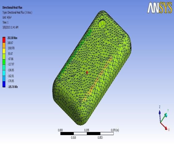
ISSN: 2319-5967
                                         ISO 9001:2008 Certified
            International Journal of Engineering Science and Innovative Technology (IJESIT)
                                       Volume 2, Issue 6, November 2013
algorithms.The mesh influences the accuracy, convergence and speed of the solution. Here the cell phone
models are meshed by treating the cell phone elements as 3D-10 noded tetrahedral thermal solid elements
(SOLID87).
A. Material Properties
Go to the ANSYS Main Menu Click Preprocessor> Material Props> Material Models, Choose Thermal>
Conductivity> Isotropic (Double click).
k(plastic) = 0.18 W/m-K oose Define Material Model Behavior > Material> New Model and define
conductivities for the model, that of innards 10 W/m-K and for the next material plastic case as 0.12 W/m-K,
NOKIA LUMIA 900 : 127.8mm long x 68.5 mm wide x11.5 mm thick

                Fig:1.Sony Xperia Tipo                               Fig: 2 SONY XPERIA TIPO

The above meshed part gets checked in ANSYS for to analyze heat transfer in mobile, thermal flux and thermal
error of cellular phone. Rest of the part has been done on ANSYS WORKBENCH.

                                                   IV. ANALYSIS
Finite Element Analysis is a numerical method of deconstructing a complex system into very small pieces (of
user designed size) called elements. The software implements equations that govern the behaviour of these
elements and solves them all creating a comprehensive explanation of how the system acts as a whole. This type
of analysis is typically used for the design and optimization of a system for too complex to analyse by hand.
Systems that may fit into this category are too complex due to their geometry, scale, or governing equations.
The following types of analysis are Thermal, Fluid flow, Magnetic, Acoustics/ vibration and Coupled fields.
ANSYS is general-purpose finite element analysis (FEA) software package.
A. Thermal Analysis
ANSYS is capable of both steady and unsteady state and transient analysis of any solid with thermal boundary
conditions. Steady-state thermal analysis calculates the effects of steady thermal loads on a system or
component. Users often perform a steady-state analysis before doing a transient thermal analysis, to help
establish initial conditions. A steady-state analysis can also be the last step of a transient thermal analysis;
performed after all transient effects have been diminished. ANSYS can be used to determine temperatures,
thermal gradients, heat flow rates, and heat fluxes in an object that are caused by thermal loads that do not vary
over time. Such loads include the following: Convection Radiation, Heat flow rates Heat fluxes (heat flow per
unit area).
A steady-state thermal analysis may be either linear, with constant material properties; or nonlinear, with
material properties that depend on temperature. The thermal properties of most material vary most material vary
with temperature. This temperature dependency being appreciable, the analysis becomes nonlinear. Radiation
boundary also makes the analysis nonlinear. Transient calculations are time dependent and ANSYS can solve
both distributions as well as create video for time incremental display of models.

B. Procedure for ANSYS analysis
The procedure for ANSYS analysis can be divided in to three distinct steps.
1.      Build the model.
2.      Apply boundary conditions and obtain the solution.

                                                      447
ISSN: 2319-5967
ISO 9001:2008 Certified
International Journal of Engineering Science and Innovative Technology (IJESIT)
Volume 2, Issue 6, November 2013
3. Review the results.
C. Pre-processing
The basic steps to build the model for an ANSYS analysis.
1. Specify the job name and title. Enter PREP7 (ANSYS pre-processor).
2. Specify the element types.
3. Specify the element real constants.
4. Specify the material properties.
5. Define the model geometry.
6. Exit
7. PREP7
To obtain the solution
The basic steps in the solution phase vary depending on the type of analysis being performed. A summary of the
basic steps in the solution phase follows.
1. Enter solution.
2. Specify the analysis type.
3. Apply the boundary conditions.
4. Start the solution.
5. Exit solution
D. Boundary conditions:
1) All faces except that of the battery have convective boundary layers.
2) The convective film coefficient. (h = 50 W/(m^2*K))
3) Heat is uniformly generated in the bock at a rate of 20 W/m^2.
4)Apply Convection- Film Coefficient as 50 W/m2K and Bulk Temperature as 300K 5)Apply Heat Generation-
Pick the battery part only and place the magnitude of Heat Generation as 139843 W/m 3(The voltage of the
battery is rated as 4 volts
Internal resistance is on the order of 200 milli-ohm
The total power is I2R = 3.200 Watts
i.e., the total power per unit volume is 139843 W/m3 )
E. Post-processing
Post processing means review in the results of an analysis, and so on.
V. RESULTS
A. Introduction
The analysis is carried out for nodal temperatures distribution, thermal flux and thermal errors distributions in
all the three dimensions (x, y, z).
The thermal analysis (or) contour plots of cell phone are shown in fig.
The maximum and minimum values of nodal temperatures, thermal fluxes and thermal errors are
tabulated.
B. Nodal Temperature Distribution
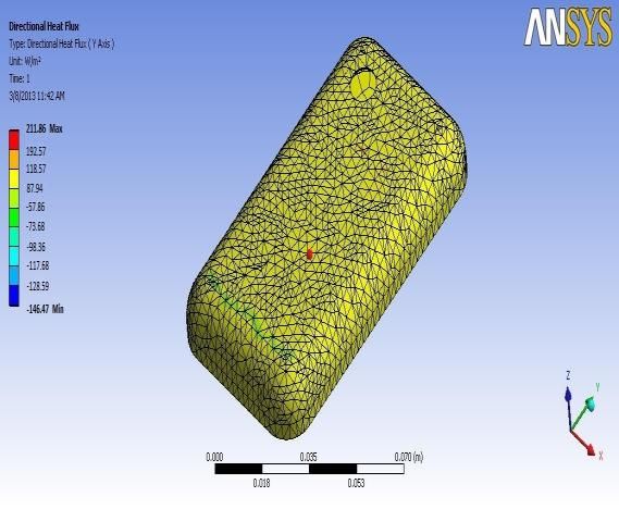
Fig 3: Nodal Temperatures for Fig4: Thermal Flux for Sony Xperia Tipo
Sony Xperia Tipo along X- Direction - Rear View
448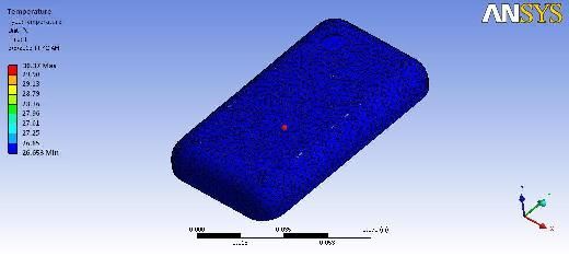
ISSN: 2319-5967
                                           ISO 9001:2008 Certified
            International Journal of Engineering Science and Innovative Technology (IJESIT)
                                    Volume 2, Issue 6, November 2013
From ANSYS WORKBENCH, temperatures are found. In fig red colour indicates the maximum temperature
and blue colour indicates minimum temperature.30.37°C is the maximum temperature value and 26.653°C is the
minimum temperature value. The maximum temperature is at battery due to higher conductivity and the
minimum temperature is at panel.

C. Directional Heat Fluxes
Thermal fluxes for Sony Xperia Tipo are found along X - direction. From fig4,Red colour indicates the
maximum thermal flux and blue colour indicates the minimum thermal flux along X-direction.The maximum
value is 202.38 W/m2 and the minimum value is -185.76 W/m2. Thermal fluxes for Sony Xperia Tipo are found
along Y - direction. From fig5 Red colour indicates the maximum thermal flux and blue colour indicates the
minimum thermal flux.The maximum value is 211.86W/m2 and the minimum value is              -146.47 W/m2.
Thermal fluxes for Sony Xperia Tipo are found along Z –direction. From       fig 6,Red colour indicates the
maximum thermal flux and blue colour indicates the minimum thermal flux.The maximum value is 98.64 W/m2
and the minimum value is -459.73 W/m2.

              Fig 5: Thermal Fluxfor Sony Xperia Tipo            Fig 6: Thermal Fluxfor Sony Xperia Tipo
                       along Y- Direction - Rear View             along Z- Direction - Rear View

D. Heat fluxes:
Heat fluxes are surface loads, when the amount of heat transfer across the surface is calculated through ANSYS.
A positive heat flux indicated that heat flowing into the element. Heat flux is used only with solid and shells.

E. Summarized Results:
                                                           Nokia Lumia 900
          S.No                     Type
                                                           Min                     Max

          1                        Nodal temperature(K)    299.653                 303.37

                                   Thermal flux (W/m²)
                                   Along X
          2                                                -185.76
                                   Along Y                                         202.38 211.86
                                                           -146.47
                                   Along Z                                             98.64
                                                           -459.73

     NOTE: The „-‟ sign indicates the direction of heat transfer

F. Validation of results:
                                                            Referred paper [8]     Present     project
               S.No         Type                            results                results
                                                            Min         Max        Min        Max
               1            Nodal temperature(K)            294.01      302.32     299.653    303.37

                                                          449
ISSN: 2319-5967
ISO 9001:2008 Certified
International Journal of Engineering Science and Innovative Technology (IJESIT)
Volume 2, Issue 6, November 2013
VI. CONCLUSION AND FUTURE WORK
In cell phones heat will be generated .For efficient working of cell phones and to prevent inconvenience for the
users, the generated heat must be efficiently transferred. If the heat dissipation is not effective, then the users
feel inconvenience. By doing the thermal analysis of cell phones, it is possible to study the heat transfer
phenomena occurring in cell phones i.e., temperature at all points, thermal fluxes and thermal gradients. The
inferred conclusions are
The applications and uses of finite element analysis and ansys are mentioned.
The general process of finite element analysis is mentioned.
The modelling part of the cell phone is done in order to carryout the analysis on the cell phone.
If the temperatures are more then the user may feel discomfort. So, for the best model the temperature ranges in
cell phone must be near to body temperature. Generally body temperature is 303 k. In the first step of analysis
by giving boundary conditions we find out the maximum and minimum nodal temperatures.
The maximum nodal temperature is 303.37 (K)
The minimum nodal temperature is 299.653 (K)
A. Future work
In future, this work may be preceded based on Size Optimization, Material Optimization, and Cost
Optimization.
REFERENCES
[1] BIRCHER, W.L., and JOHN, L.K.Complete system power estimation: A trickle-down approach based on performance
events. In Proceeding of the IEEE International Symposium on Performance Analysis of Systems and Software(San
Jose,CA,USA,Apr.2007)
[2] BIRCHER, W.L., and JOHN, L...Analysis of dynamic power management on multi-core processors, In Proceedings of
the 22nd International Conference on Supercomputing. 2008.
[3] MAHESRI, A., and VARDHAN, V.Power consumption breaks down on a modern laptop. In Proceedings of the 2004
work shop on Power-Aware Computer Systems., 2004.
[4] Pierce, A.D.,”Acoustics: An Introduction to Physical Principles and Applications”, Acoustical Society of America.,
1989.
[5] Andrea. goldsmith and Professor My T.Le.,”Waterproof of an cellular phone design”, 2006.
[6] Wei Lic, Hongyi Li.,”Impact Analysis of A cellular phone”.1989.
[7] Ronan Grimes, Ed Walsh, Pat Walsh., “Active Cooling Of A Mobile Phone Handset ‟‟ATE 3133. 2010.
[8] Professor Frank Fisher.,”ME345Modeling and Simulation 3D Heat conduction within solid cell-phone”2012.
[9] Tan, F.L.and C.P.Tso, “Cooling of mobile electronic devices using phase change material.”Applied Thermal Eng.,
2004.
450You can also read