MOTORIZED PROJECTOR LIFT - MOD. SI-H XL 300 (version MAY-2021)
←
→
Page content transcription
If your browser does not render page correctly, please read the page content below
MOTORIZED PROJECTOR LIFT
                          MOD. SI-H XL 300 (version MAY-2021)
                                INSTALLATION MANUAL
Thank you for purchasing the new SI-H XL 300 Projector Lift.
The SI-H XL 300 is supplied with a set of components and accessories that make it suitable for installation for
the majority of standard AV applications, but note must be made of the restrictions that apply to the weight
capability of this unit and not exceeded.
BEFORE INSTALLING THE LIFT, PLEASE READ THE FOLLOWING INSTRUCTIONS CAREFULLY. Please, always
keep these instructions so that anyone can read them when needed.
THE MANUFACTURER DOES NOT TAKE RESPONSIBILITY FOR ANY DAMAGE TO PROPERTY OR PERSONAL
INJURY IF THE PROJECTOR LIFT IS USED OUTSIDE OF RECOMMENDED SPECIFICATIONS OR IN CASE OF
INCORRECT INSTALLATION.

INSTALLATION OF SI-H XL 300 PROJECTOR LIFT HAS TO BE CARRIED OUT FROM QUALIFIED
PERSONNEL ONLY.

Before installing the projector lift, please read the following instructions carefully:
   • The projector lift must be used INDOORS ONLY.
   • IT IS FORBIDDEN TO STAY UNDER THE LIFT AND WITHIN A RANGE OF 3 MT. FROM THE
       LIFT.
   • IN CASE OF MAINTENANCE, UNPLUG THE POWER SUPPLY.
   • Please confirm that your projected image width will fit your screen from your proposed
       mounting location prior to installation.
   • Incorrect use of the lift, including exceeding the maximum lifting weight, will be
       dangerous. The manufacturer does not take responsibility for any damage o property or
       personal injury if the lift is used outside of recommended specifications.
   • This product uses a 230V AC Motor. DO NOT attempt to service the motor. Incorrect
       servicing could lead to risk of electric shock.
   • For any repairing, please contact directly the dealer you purchased the unit from.
   • Check at least once a year that the screws of the steel cables are well tightened and that
       the steel cables are in good conditions. In case they have signs of usage or damages,
       replace them promptly with the original ones supplied by the manufacturer.
   • Check every 6 months that screws, wall plugs and brackets are in good conditions and
       well tightened.

The manufacturer and his agents do not take responsibility for any damage to property
or personal injury if the winch is installed/used outside of recommended
specifications.

            This product uses a 230 V AC motor. DO NOT attempt to carry out repairs to
            the motor, there are no user serviceable parts.

Incorrect servicing could lead to risk of electric shock. In the event of a fault, please
contact the dealer /supplier. Warranty is 24 months Return To Base.

The projector lift SI-H XL 300 is               certified.

                                                                                                             1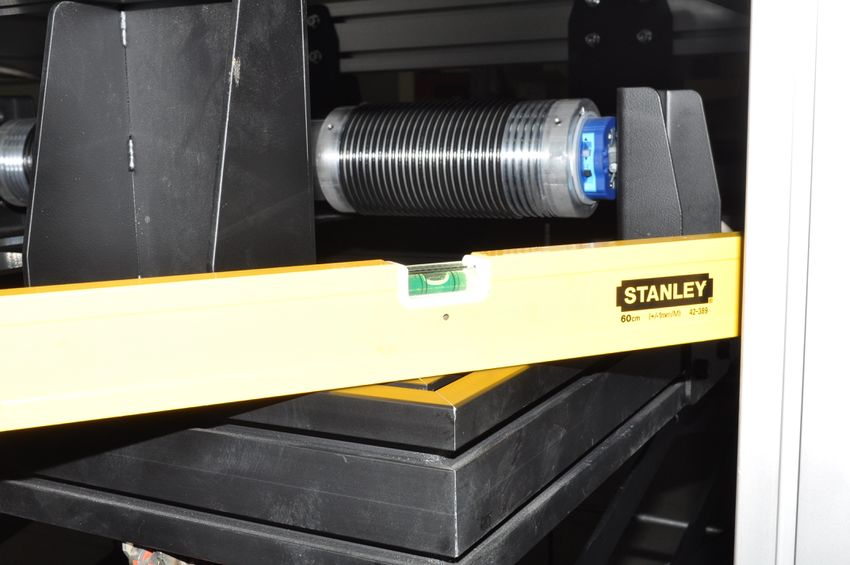
WARRANTY CONDITIONS

    This projector lift is guaranteed 2 years from the purchase date for manufacturing defects and
    5 years on motor defects.
    Responsibility is limited to repairing or substitution of the defected components and without any
    other charge at our expense.
    Warranty is officially voided if the lift has been dismantled or it is returned with collision damage
    or defective due to incorrect installation. Repairs must be carried out by an Approved ScreenInt
    Certified Engineer.
    Warranty is officially voided if (all the following cases are including but not limited):
    1)    defects not due to deficiencies in the material or workmanship;
    2)    amendments, alterations, repairs or disassembling of the Product not previously
    authorized in writing by Screenint;
    3)    installation, use or maintenance of the Product not in compliance with Screenint ‘s
    instructions as set forth in this Installation Manual and/or in any other technical documentation
    supplied together with the Product;
    4)     bad and/or improper and/or not in compliance installation, maintenance, negligence,
    improper use;
    5)     use of non-original spare parts or not authorized in writing by Screenint;
    6)    normal wear and tear;
    7)    the motor is removed / dismantled;
    8)    the projector lift has been damaged in transit;
    9)    the instructions regarding the electrical connections have not been followed;
    10) the products have to be installed following the electric regulations (CEI) and the other
    local specific laws;
    11) in the installation are used electric interfaces that does not allow the correct time lapse
    between up and down operation (complete cut down of electric power on both phases for one
    second)
    12) electrical accessories have been used that are incompatible with the lift motor causing
    damage to its internal components;
    13) the sticker regarding the serial number of the product has been altered, deleted, removed
    or tampered.

                                     SUPPLIED EQUIPMENT LIST
    When you open the packaging, please CHECK that it contains ALL the components below listed. In case one
    or more components are missed, please refer to the dealer you purchased the product from.
    A) 1 MECHANIC PROJECTOR LIFT SI-H XL 300
    B) 4 METAL BRACKETS FOR CEILING MOUNTING
    C) 16 SOCKET HEAD SCREWS 8X20
    D) 16 M8 WASHERS
    E) 16 M8 CROWNED NUTS
    F) RF REMOTE CONTROL
    G) INSTALLATION MANUAL

                              B                            CDE                             F
A
                                                                                                          2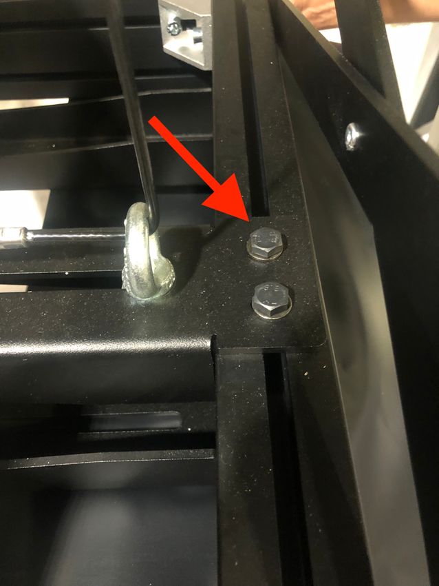
CEILING MOUNTING
- In order to mount the four metal brackets shown on Fig. “B” above on the upper aluminium frame of the
SI-H XL 300, please use screws, washers and crowned nuts mentioned on “C, D, E” of the supplied
equipment list; put inside the groove of the aluminium frame the crowned nut as shown on Fig. 1A;
connect the ceiling bracket to the profile by the socket head screws and the crowned nuts, move the
ceiling bracket along the profile in order to position it where needed (Fig. 1B); now tighten firmly the
screws of the four brackets.
Fig. 1A Fig. 1B
- Note: the four ceiling mounting brackets can be mounted in two different ways on the upper frame of
the lift:
1- Brackets mounted towards outside – Fig. 8A – page 7
2- Brackets mounted towards inside – Fig. 8B – page 7
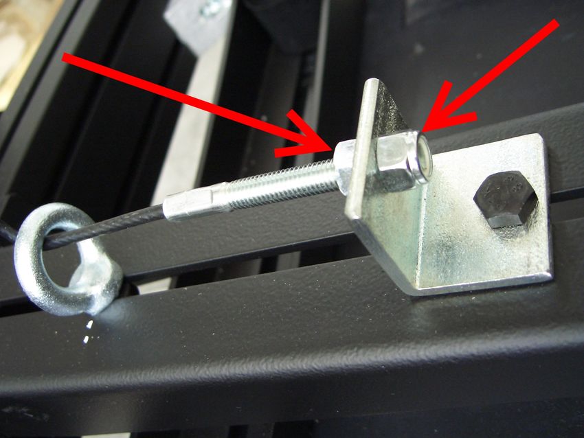
- Once the four brackets have been mounted on the upper frame of the lift, mount the lift to the ceiling
using wall plugs and screws (NOT supplied) specific for the type of material to drill. During the installation
pay attention that the lift is perfectly levelled both on the width and on the depth. (See Fig. 2).
Fig. 2
ELECTRIC CONNECTION
- The motor has the possibility to be controlled via the supplied handheld RF remote control or via wired
low voltage contact closures.
- The motor has a six-core power cable. NEVER CONNECT THE MAINS TO THE WIRES WHITE, WHITE-
BLACK, WHITE-ORANGE.
- Once the lift is mounted to the ceiling, connect the wires brown, blue and yellow/green to the mains,
following the scheme shown in Fig. 3A;
- The lift is supplied with a safety mechanism (Fig. 3B) with a double security system: first - this is a
mechanic safety system that prevents the steel cable to unroll when the speed has reached 50 rpm;
second – this is an electrical security system that disconnect the electrical connection of the motor if the
force driven on the steel cable, caused by the falling down, is more than 503 Nm.
Fig. 3A Fig. 3B
3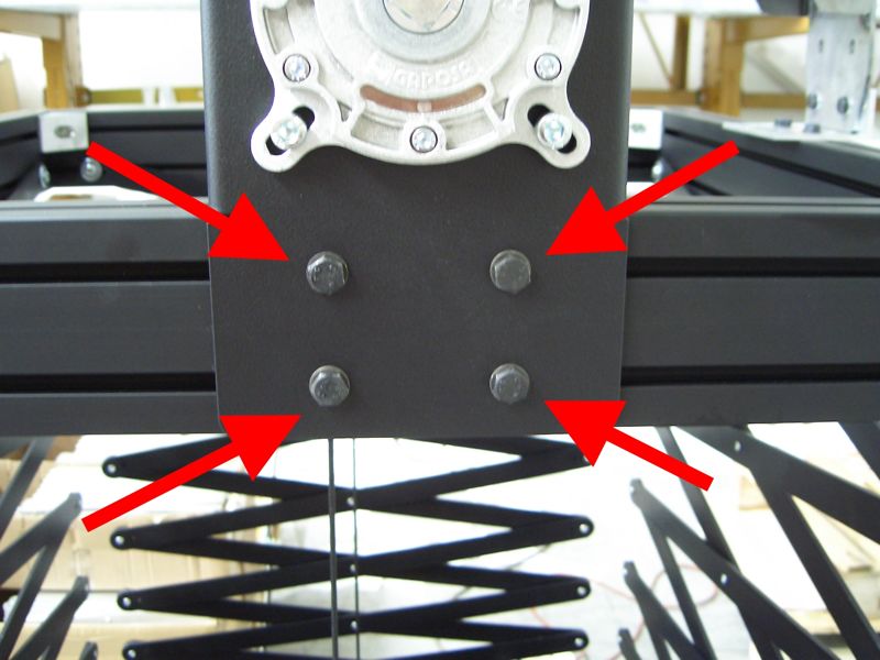
FIXING THE PROJECTOR TO LIFT
- Roll down the SI-H XL 300 by pushing ▼ button on the remote control (Fig. 7A), in order to lower the lift
till the lower end-stop (SERVICE mode), preset in the factory at 2,5 mt. ca. In case you wish to modify
the lower end-stop (SERVICE mode), please refer to instructions at page 4 and 5.
In order to fix the projector under the lift, position the splines of the three profiles of the lower lift frame,
to match the anchoring points on the projector (Fig. 4A).
Unloose the four screws as shown on Fig. 4B and position the three profiles where needed (Fig. 4C).
Once you have aligned the splines of the profiles with the anchoring points on the projector, tighten the
screws and the bolts of the profiles following a cross scheme.
Repeat this step until all the screws on the three profiles will be very well tightened.
Insert the screws for mounting the projector in the milling of the profiles (milling depth 10 mm) and
tighten the screws to the anchoring points of your projector.
Fig. 4A
Fig. 4B Fig. 4C
ADJUSTMENT OF PITCHING AND ROLLING OF THE PROJECTOR
Projectors have not a regular distribution of the weight on their surface but tent to have unbalancing caused
by the lamp, by the optical system and so on.
Unbalancing could lead to either a right and left rolling or a pitching of the lower lift frame - projector.
The SI-H XL 300 have been developed to solve these problems and allow to adjust the lift in order to get a
perfect balance of the entire lifting system.
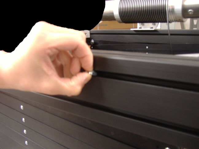
In order to adjust PITCHING, please move the motor along the profile where the motor itself is fixed, by
loosing the screws as shown on Fig. 5A and 5B and move the motor left or right until the lower frame will be
perfectly balanced (Fig. 5C).
Fig. 5A Fig. 5B Fig. 5C
PLEASE, PROCEED WITH THIS STEP, AFTER HAVING LAYED THE PROJECTOR MOUNTED ON THE
FRAME ON A SUPPORT SURFACE, IN ORDER TO LIGHTEN THE MOTOR FROM THE WEIGHT.
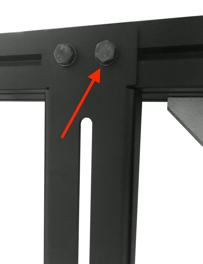
Now loose the screws on Fig. 5D and using a rubber hammer, move the profile of Fig. 5E, left or right in
order that the steel cables are perpendicular both to the upper part and to the lower part of the lift (see Fig.
5F). At the end of the adjustment, tighten the screws firmly (Fig. 5D).
4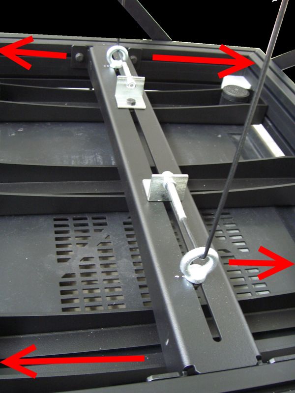
Fig. 5D                    Fig. 5E                               Fig. 5F

In order to adjust ROLLING, please tighten or unloose the nuts that act on the tension of the steel cables.
(Fig. 6A)

                               Fig. 6A

                                ADJUSTMENT OF THE END STOPS
                                   PLEASE READ CAREFULLY
The SI-H XL 500 motorized lift is supplied with a remote control that allows to set three positions:
    1- CLOSED LIFT: preset by the factory, in closed upper position. WARNING: in case the installer
       needs to modify this end-stop, it is ONLY allowed to lower the upper end-stop position. Do not try
       to raise the upper end-stop because this will cause severe damages to the product and
       this operation will invalidate the warranty.
    2- PROJECTION MODE: intermediate stop position, NOT preset by the factory.
    3- SERVICE MODE: lower end-stop position, preset by the factory at 2,5 mt. circa.

How to modify the end-stops:
A- SETTING OF THE LOWER END STOP (SERVICE MODE)
   - Lower down the lift till half stroke, pressing the remote control button ▼ and stop it with button ◼.
   - Press the button ◼ (for 5 secs) till the motor swivels 2 times.
   - Press again the button ◼ (for 5 sec) till the motor swivels 4 times.
   - Press the button ▼ (for 5 sec) till the motor swivels 2 times.
   - Press the buttons ▼ or ▲in order to the reach the desired position of the lift. Warning: during this
     programming operation you have to keep the buttons ▼ or ▲ pressed in order to reach the desired
     position.
   - Once this position is reached, in order to memorize it press the button ◼ (for 5 sec) till the motor
      swivels 3 times.

                                                                                                              5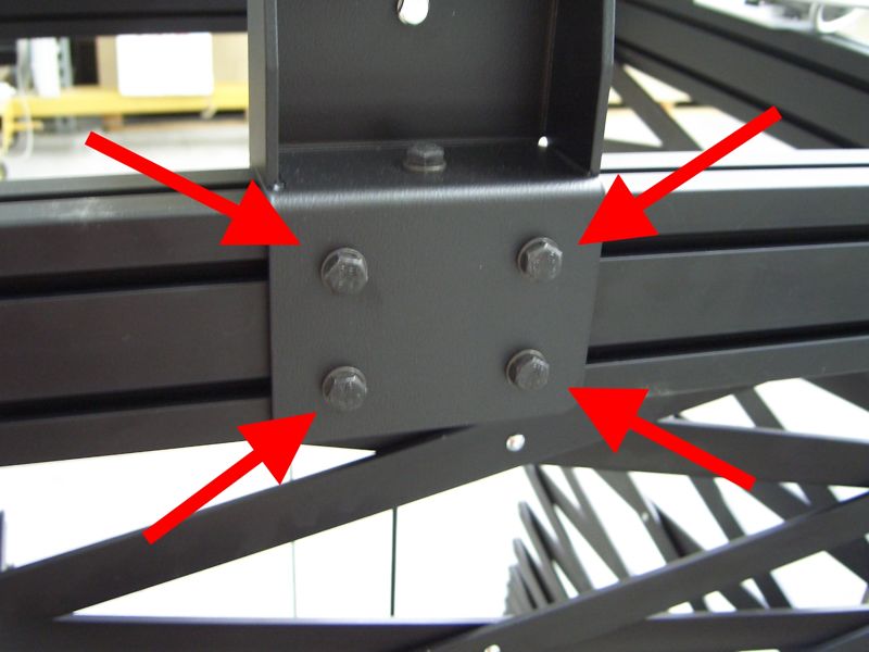
B- SETTING OF THE UPPER END STOP
WARNING: in case the installer needs to modify this end-stop, it is ONLY allowed to lower the upper end-
stop position. Do not try to raise the upper end-stop because this will cause severe damages to
the product and this operation will invalidate the warranty.

   - Lower down the lift till half stroke, pressing the remote control button ▼ and stop it with button ◼.
   - Press the button ◼ (for 5 secs) till the motor swivels 2 times.
   - Press again the button ◼ (for 5 sec) till the motor swivels 4 times.
   - Press the button ▲ (for 5 sec) till the motor swivels 2 times.
   - Press the buttons ▼ or ▲in order to the reach the desired position of the lift. Warning: during this
     programming operation you have to keep the buttons ▼ or ▲ pressed in order to reach the desired
     position.
   - Once this position is reached, in order to memorize it press the button ◼ (for 5 sec) till the motor
      swivels 3 times.

C- SETTING OF THE INTERMEDIATE STOP (PROJECTION MODE)
   - Lower down the lift till half stroke, pressing the remote control button ▼ and stop it with button ◼.
   - Press the button ◼ (for 5 secs) till the motor swivels 2 times.
   - Press again the button ◼ (for 5 sec) till the motor swivels 4 times.
   - Press simultaneously the buttons ▲+▼ (for 5 sec) till the motor swivels 2 times.
   - Press the buttons ▼ or ▲in order to the reach the desired position of the lift. Warning: during this
     programming operation you have to keep the buttons ▼ or ▲ pressed in order to reach the desired
     position.
   - Once this position is reached, in order to memorize it press the button ◼ (for 5 sec) till the motor
      swivels 3 times.

D- USE OF THE REMOTE CONTROL
       -   Press the button ▼ in order to reach the lower-end stop (SERVICE mode).
       -   Press the button ▲ in order to reach the upper-end stop.
       -   Press simultaneously the buttons ▲+▼ in order to reach the intermediate
           stop (PROJECTION mode).
                                                                                                    Fig. 7A
E – CONNECTION OF LOW VOLTAGE CONTACTS TO REACH THE DIFFERENT END-STOPS
       -   Close the connection, for at least 1 second, between the white-black and white-orange wires in
           order to reach the LOWER end stop (SERVICE mode).
       -   Close the connection, for at least 1 second, between the white-black and white wires in order to
           reach the UPPER end stop.
       -   Close the connection, for at least 1 second, simultaneously between the white-black, white-orange
           and white wires in order to reach the INTERMEDIATE stop (PROJECTION mode).

The SI-H XL 300 projector lift includes a CABLE MANAGEMENT
SYSTEM.
In order to fit in the power and signal cables of the projector
Move the lift in the lower end stop position (SERVICE MODE),
and open the small doors, as shown in Fig. 7B.

                                                                                                         Fig. 7B
                                                                                                               6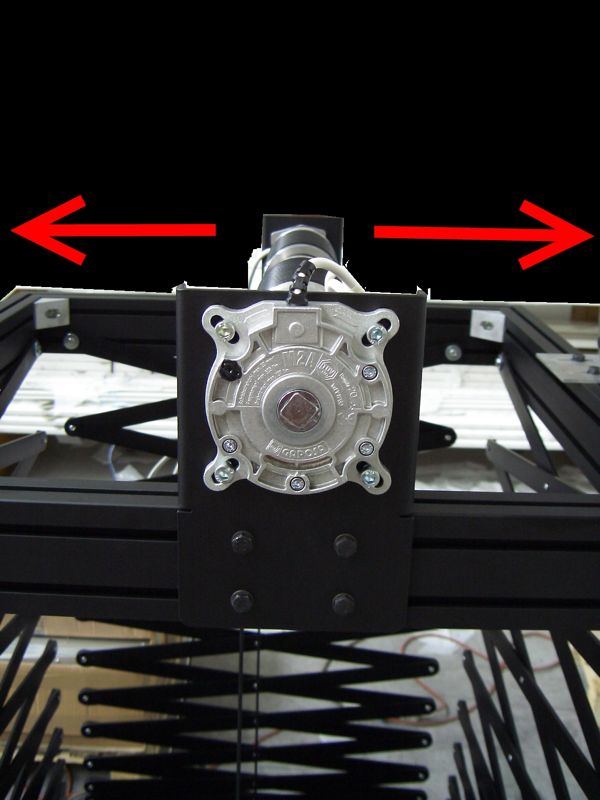
TECHNICAL SPECIFICATIONS

                      B
         A                                    Fig. 8
                               265

                                       MAX 3576
                                       MIN 576
                          90
                               210
                               11 90

POWER SUPPLY                                           230 V 50HZ
CONSUMPTION                                            360 W
TORQUE                                                 80 Nm
MOTOR SPEED                                            12 rpm
ROLL UP/DOWN SPEED                                     17 sec./metre
TERMICAL STOP                                          after 4 minutes of operation
NET WEIGHT LIFT SI-H XL 300                            kg. 71
MAXIMUM LOAD OF THE PROJECTOR                          kg. 95
DIMENSIONS SI-H XL 300 CLOSED                          790x576x890 (WxHxD in mm.)
DIMENSIONS SI-H XL 300 OPENED                          790x3576x890 (WxHxD in mm.)

                                                                                      7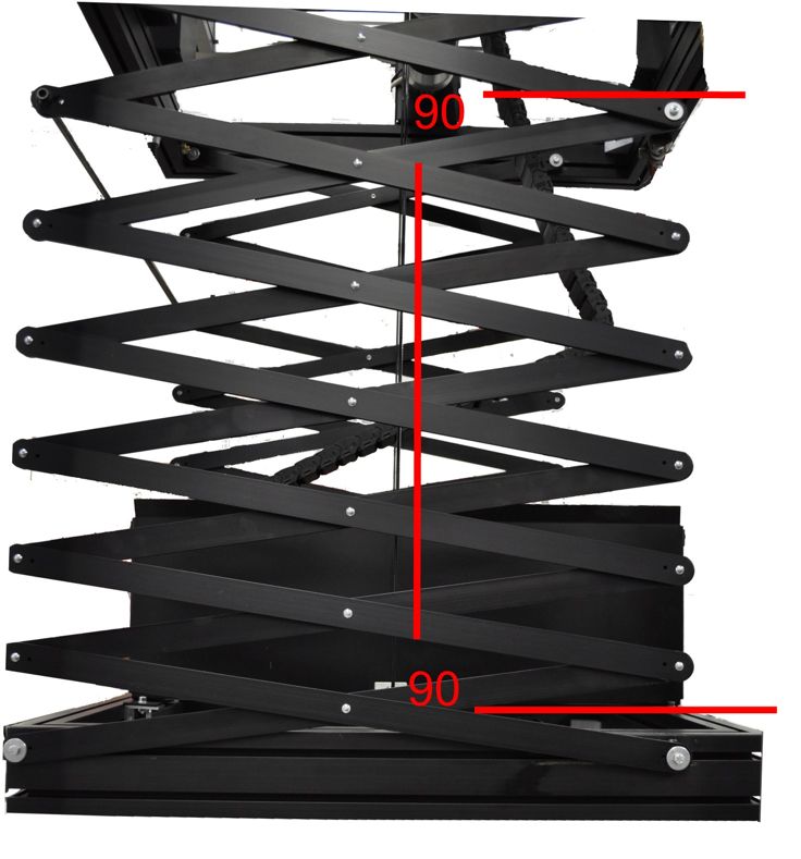
You can also read