MULTI-TOOL OWNERS MANUAL - ParkerBrand

Page created by Brett Banks
 
CONTINUE READING
MULTI-TOOL OWNERS MANUAL - ParkerBrand
MULTI-TOOL
P G M T- 5 2 0 0    OWNERS MANUAL
MULTI-TOOL OWNERS MANUAL - ParkerBrand
INTRODUCTION                                                                                                                                                                                                                                                                                                                                                          CONTENTS

                                                                                                        GENERAL SAFETY ................................................................................................ 4-5                 CHAINSAW GEARBOX LUBRICATION .................................................. 39
            This manual has been produced by Parker Products Ltd. and should be kept with the           SAFETY SYMBOLS ............................................................................................... 6-9                  CHAIN OIL ................................................................................................................... 40-41
                  product and referenced for operation, maintenance and troubleshooting.                FOR SAFE OPERATION ..................................................................................... 10-13                      INSTALLING THE POLE EXTENSION ..................................................... 42-43
                                                                                                        WHATS IN THE BOX? .......................................................................................... 14-15                  THE HARNESS ......................................................................................................... 44-46
               This manual contains an overall description of the product, together with all the        PRODUCT FEATURES ........................................................................................ 16-19                     STARTING THE ENGINE ................................................................................... 48-51
                 necessary information for using the product correctly and safely. It is highly         BEFORE USING THE MULTI-TOOL .......................................................... 20-21                                        STOPPING THE ENGINE .................................................................................. 52
       recommended that this manual is read prior to any operation or maintenance of this product.      ASSEMBLY .................................................................................................................. 22-25   OPEN & REPLACE SPOOL LINE ............................................................... 54-57
       The safety precautions and warnings are to ensure your safety and protect you from harm or       LOCKING THE HUB .............................................................................................. 26                   ADJUSTING THROTTLE CABLE & IDLING SPEED ...................... 58
                                           damage to the product.                                       INSTALLING THE 3 TOOTH BLADE ......................................................... 27-29                                        OPERATION ................................................................................................................ 60-66
                                                                                                        INSTALLING THE SPOOL ................................................................................ 30-31                         TROUBLE SHOOTING ........................................................................................ 68-73
       All photographs and drawings in this manual are supplied by Parker Products Ltd. to help you     INSTALLING HEDGE TRIMMER ATTACHMENT ............................. 32                                                                MAINTENANCE & CARE .................................................................................. 74-76

       with the operation and maintenance of the product. The information contained in this manual      INSTALLING CHAINSAW ATTACHMENT ............................................. 33                                                     SPECIFICATIONS ................................................................................................... 77

       was accurate at the time of production, however Parker Products Ltd. may make modifications to   ADJUSTING HEDGE TRIMMER ANGLE ................................................ 34                                                   GUARANTEE .............................................................................................................. 78
                                                                                                        HEDGE TRIMMER GEARBOX LUBRICATION ................................... 35                                                            DECLARATION OF CONFORMITY ........................................................... 79
                                       the product without notification.
                                                                                                        FITTING THE CHAIN, BAR & TENSIONING CHAIN...................... 36-38

2                                                                                                                                                                                                                                                                                                                                                                                 3
MULTI-TOOL OWNERS MANUAL - ParkerBrand
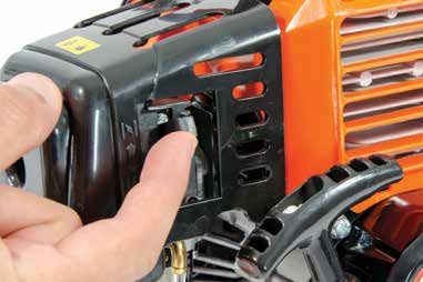
GENERAL SAFETY                                                                                                                                                                                                                                  GENERAL SAFETY

                                                                                                                                         For safe operation and maintenance symbols are moulded in relief on the machine or shown on a label.

    •   WARNING! Never allow children or anyone who does not fully understand the directions given in the manual to use the machine.
    •   ALWAYS USE safety equipment; appropriate footwear, eye protection, ear protection, head protection, trousers and gloves.                 WARNING
                                                                                                                                                                                                                         FUEL FILLER POINT
                                                                                                                                                 To reduce the risk of injury, user must read
    •   DO NOT wear loose clothing, jewellery, short trousers, sandals, or go barefoot.                                                          instruction manual.
    •   NEVER start the engine inside a closed room or building.
    •   NEVER use the product when ground is slippery, at night, during rain storms, lightning storms, or at times of strong wind.
                                                                                                                                                                                                                         THE DIRECTION TO CLOSE THE CHOKE
    •   DO NOT start the engine within 3m of the fuelling point.                                                                                 GLOVES
    •   REMOVE all sources of sparks and flames before mixing and pouring fuel.                                                                  Gloves should be worn where appropriate.
    •   DO NOT let anyone with in 15m of the product while in operation.
    •   INSPECT the entire unit for loose fasteners and fuel leakages, Make sure that the cutting attachment is properly installed.              HEAD, EYE & EAR PROTECTION                                              THE DIRECTION TO OPEN THE CHOKE
    •   DO NOT start cutting until you have a clear cutting area and a secure footing.                                                           Approved head, eye & ear protection should be
    •   ALWAYS use the harness supplied while operating the machine.                                                                             worn at all times during operation.
    •   NEVER smoke while operating the unit or refilling its fuel tank.                                                                                                                                 MIN       MAX
    •   ALWAYS keep the handles dry, clean and free of oil and fuel mixture.                                                                                                                                             CHAIN OIL ADJUSTMENT SCREW
    •   ALWAYS shut off the engine before putting the product down.                                                                              BOOTS
    •   MAKE SURE all fuel is removed before transportation.                                                                                     Wear sturdy, non-slip boots.
    •   ALL MAINTENANCE other than that listed in this manual should be carried out by professionally trained and certified personnel.
                                                                                                                                                 CLOTHING                                                                ON
                                                                                                                                                 Appropriate clothing should be worn during
                                                                                                                                                 operation. Ensure clothing is made of strong                            OFF
                                                                                                                                                 fabric and is not baggy or loose.

4                                                                                                                                                                                                                                                           5
MULTI-TOOL OWNERS MANUAL - ParkerBrand
SAFETY SYMBOLS                                                                                                                                                                              SAFETY SYMBOLS

                                                     This symbol, before a safety comment, indicates a
                                                     PRECAUTION, a WARNING or a DANGER. Ignoring                   15m (50ft)     Keep all children, bystanders   WARNING! Never operate this power tool
     WARNING! To reduce the risk of injury,          this warning can lead to an accident for yourself or for                     & helpers 15 metres away from
     user must read instruction manual.              others. To limit the risk of injury, fire, or electrocution                  the machine.                    within 50ft (15M) of wires or power cables.
                                                     always apply the recommendations indicated.

     DANGER! Petroleum spirit is highly flammable.                                                                      KEEP BY STANDERS AWAY.
     No smoking or naked light.                      RISK OF FIRE - Do not add fuel when operating.                                                               BEWARE OF SHARP BLADES

                                                                                                                                                                  DO NOT TOUCH THE MOVING PARTS OF
     DANGER! Keep away from sources of ignition.     EXPLOSION HAZARD                                                   BEWARE OF THROWN OBJECTS                  THE MACHINE UNTIL THEY ARE
                                                                                                                                                                  COMPLETELY STOPPED.

                                                                                                                                                                  RISK OF INJURY. DO NOT OPEN OR
     FLAMMABLE                                       Fuel/2-stroke oil mixture ratio.                                    WARNING! Danger of kickback.             REMOVE SAFETY SHIELDS WHILE
                                                                                                                                                                  ENGINE IS RUNNING.

6                                                                                                                                                                                                               7
MULTI-TOOL OWNERS MANUAL - ParkerBrand
SAFETY SYMBOLS                                                                                                                                                                       SAFETY SYMBOLS

                                                                                                                 WARNING! Use of this product can pose a
                                                                                                                 danger to wildlife. Check areas, particularly   WASTE ELECTRICAL PRODUCTS SHOULD NOT BE
                                                  REMOVE SPARK PLUG LEAD BEFORE                                  long grass and under bushes for signs of life
     WARNING! Spinning cutting line.                                                                             if necessary relocate.                          DISPOSED OF WITH HOUSEHOLD WASTE. PLEASE
                                                  MAINTENANCE                                                    NOTE: Not all animals will be deterred by       RECYCLE WHERE FACILITIES EXIST CHECK YOUR
                                                                                                                 the noise of the product alone.                 LOCAL AUTHORITY OR RETAILER FOR RECYCLING
                                                                                                                                                                 ADVICE

     WARNING! Risk of entanglement.
                                                  WARNING! Never to touch the spark plug or
                                                  plug cord while the engine is in operation. Doing                                                              GUARANTEED SOUND POWER LEVEL
                                                  so may result in being subjected to an electrical
                                                  shock.                                              6600 MIN
                                                                                                                 Maximum speed of the applicable cutting unit.

     WARNING! Protect feet from risk of injury.
                                                                                                      7100 MIN

                                                  WARNING! Do not use the Multi Tool in an
                                                  enclosed space. Exhaust fumes contain
                                                  dangerous carbon monoxide.
     HOT SURFACES WILL BURN FINGERS OR PALMS                                                                     CONFORMS TO CURRENT SAFETY STANDARDS

8                                                                                                                                                                                                      9
MULTI-TOOL OWNERS MANUAL - ParkerBrand
FOR SAFE OPERATION                                                                                                                                                                                                                                                                           FOR SAFE OPERATION

i   IMPORTANT                                                                     i   WORKING PLAN                                                                   i   BEFORE STARTING THE ENGINE                                                 i   STARTING THE ENGINE

    • Read this manual carefully until you completely understand and can              • You should never use this product when under the influence of                    • The area within a perimeter of 15m of the person using the product           • Keep bystanders and animals at least 15m (50ft) away from the
         follow all safety and operating instructions                                     alcohol, when suffering from exhaustion or lack of sleep, when
                                                                                                                                                                             should be considered a hazardous area into which no-one should                 operating point. If you are approached, immediately stop the engine.
    •    Keep this manual handy so that you may refer to it later whenever                suffering from drowsiness as a result of taking cold medicine or at
                                                                                                                                                                             enter. If necessary, yellow warning rope and warning signs should          •   The product is equipped with a centrifugal clutch mechanism, so the
         questions arise. Also note, if you have any questions which cannot be            any other time when a possibility exists that your judgment might be
         answered herein, contact Parker Brand.                                           impairs or that you might not be able to operate the product properly              be placed around the perimeter of the area. When work is performed             cutting attachment begins to rotate as soon as the engine is started
    •    Always be sure to include this manual when selling, lending or                   and in a safe manner.                                                              simultaneously by two or more persons, care should be taken to                 by putting the throttle trigger into the start position. When starting
         otherwise transferring ownership of this product.                            •   When planning your work schedule, allow plenty of time to rest.                    constantly look around or otherwise check for the presence and                 the engine, place the product onto the ground in a flat clear area and
    •    Never allow children or anyone unable to fully understand the                    Limit the amount of time over which the product is to be used                      locations of other people working so as to maintain a distance                 hold it firmly in place so as to ensure that neither the cutting
         directions given in the manual to use the machine.                               continuously to somewhere around 30-40 minutes per session, and                    between each person sufficient to ensure safety.                               attachment nor the throttle trigger come into contact with any
                                                                                           take 10-20 minutes of rest between sessions. Also try to keep the total       •   Check the condition of working area to avoid any accident by hitting           obstacle when the engine starts.
i   WORKING CIRCUMSTANCE                                                                  amount of work performed in a single day under 2 hours.
                                                                                                                                                                             hidden obstacles such as stumps, stones, cans or broken glass.             •   After starting the engine, check to make sure that the cutting
                                                                                      •   If you don’t observe the working time or working manner repetitive
                                                                                                                                                                         •   Inspect the entire unit for loose fasteners and fuel leakage. Make             attachment stops rotating when the throttle trigger is moved fully
    • Never start the engine inside a closed room or building. Exhaust                    strain injury could occur,
                                                                                                                                                                             sure that the cutting attachment is properly installed and securely            back to it’s original position. If it continues to rotate even after the
         gases contain dangerous carbon monoxide.                                     •   If you feel discomfort, redness and swelling of your fingers or any
    •    Never use the product                                                            other part of your body, see a doctor before getting worse.                        fastened.                                                                      throttle trigger has been moved fully back, turn off the engine
            1. when the ground is slippery or when you can’t maintain a               •   To avoid noise complaints operate product between 9am and 5pm.                 • Be sure to attach the cutting attachment guard securely in place, or             contact Parker Brand.
                stead posture.                                                                                                                                             you may injure yourself.
            2. at night, at times of heavy fog, or at any other times when                                                                                               • Always us the harness. Adjust the harness for comfort before
                your field of vision might be limited and it would be difficult                                                                                            starting the engine. The harness should be adjusted so the left hand
                to gain a clear view of the working area.
                                                                                                                                                                           can comfortably hold the handlebar grip approximately waist high.
            3. during rain storms, during lightening storms, at times of
                strong gale-force winds, or at any other time when
                weather conditions might make it unsafe to use the product.

    10                                                                                                                                                                                                                                                                                                                            11
MULTI-TOOL OWNERS MANUAL - ParkerBrand
FOR SAFE OPERATION                                                                                                                                                                                                                                                                           FOR SAFE OPERATION

i   USING THE PRODUCT                                                                i   BE CAREFUL OF SURROUNDING PEOPLE                                         i   HANDLING FUEL                                                                  i   TRANSPORTATION

    • Grip the handles firmly with both hands using your whole hand. Place               • Guard against hazardous situations at all times. Warn adults to keep       • The engine of our product is designed to run on a mixed fuel, which              • When hand-carrying the product, cover over the cutting attachment
         your feet slightly apart (slightly further apart than shoulder width) so           pets and children away from the area. Be careful if you are                   contains highly flammable gasoline. Never store cans of fuel or refill             if necessary, lift up the product and carry it paying attention to the
         that your weight is distributed evenly across both legs, and always                approached. Injury may result from flying debris.                             the tank of the unit in any place where there is a boiler, stove, wood             cutting attachment.
         be sure to maintain a steady, even posture while working.                                                                                                        fire, electrical sparks, welding sparks, or any other source of heat or        •   Never transport the product over rough roads or long distances by
    •    Keep cutting attachment below waist level.                                  i   MAINTENANCE                                                                      fire which might ignite the fuel.                                                  vehicle without removing all fuel from the fuel tank. If doing so fuel
    •    Maintain the speed of the engine at the level required to perform                                                                                            •   Never smoke while operating the unit or refilling its fuel tank.                   might leak from the tank during transport.
         cutting work, and never raise the speed of the engine above the level           • In order to maintain your product in proper working order, perform         •   When refilling the tank, always turn off the engine and allow it to
         necessary.                                                                         the maintenance and checking operations described in the manual               cool down. Take a careful look around to make sure that there are no
    •    If the unit starts to shake or vibrate, turn off the engine and check the          at regular intervals.                                                         sparks or open flames anywhere nearby before refuelling.
         whole unit. Do not use until the problem has been properly corrected.           • Always be sure to turn off the engine before performing any                •   Wipe spilled fuel completely using a dry rag if any spillage occurs
    •    Keep all parts of your body away from rotating cutting attachment                 maintenance or checking procedures.                                            during refuelling.
         and hot surfaces.                                                               • In the event that any part must be replaced or any maintenance or          •   After refuelling, screw the fuel cap back tightly onto the fuel tank and
    • Never touch the muffler, spark plug, or other metallic parts of the                  repair work not described in this manual must be performed please              then carry the unit to a spot 3m or more away from where it was
         engine while the engine is in operation or immediately after                      contact Parker Brand.                                                          refuelled before turning on the engine.
         shutting down the engine. Doing so could result in serious burns                • Under no circumstances should you ever take apart the product or
         or electrical shock.                                                               alter it in any way. Doing so might result in the product becoming
                                                                                            damaged during operation or the product becoming unable to
                                                                                            operate properly.

    12                                                                                                                                                                                                                                                                                                                          13
MULTI-TOOL OWNERS MANUAL - ParkerBrand
WHAT’S IN THE BOX                                                                                                                                                                WHAT’S IN THE BOX

                 MAIN ENGINE                                                                             LOWER GUARD                               SPOOL
                                                     Washers and nut are pre-installed on the lower
                                                 i   shaft.

                                                                                              HUB NUT

                                        HANDLE                                             WASHER ‘C’

THROTTLE TRIGGER                                                                           WASHER ‘B’
+ ON/OFF SWITCH + THROTTLE SET BUTTON                                                                                    THREE TOOTH BLADE                 BODY HARNESS
+HANDLE                                                                                     WASHER ‘A’

                                                                                       LOWER SHAFT               CHAINSAW COVER
                                                                              + SPOOL AND BLADE HUB
                                                                         + BRACKET FOR LOWER GUARD
                                                                                                                                             SPOOL LINE                   GLOVES
                                                                                     EXTENSION POLE

                                                                                                                        FUEL MIX BOTTLE

                                                                              CHAINSAW ATTACHMENT

                                                                                                                                                                                                    TOOL KIT
                                                                                                                                                                                     + SPANNER + CHAIN FILE
                                                                                                                                                                    + SPARK PLUG WRENCH + 2x LOCKING KNOBS
                                                                        HEDGE-TRIMMER ATTACHMENT
                                                                                                                                                                                             + 2x ALLEN KEYS
                                                                                   + BLADE COVERS

   14                                                                                                                                                                                                 15
MULTI-TOOL OWNERS MANUAL - ParkerBrand
PRODUCT FEATURES                                       PRODUCT FEATURES

         THROTTLE TRIGGER          ENGINE              COIL PLUG
         + ON/OFF SWITCH

         LOOP                               CHOKE       EXHAUST
         HANDLE

         SPLIT SHAFT        HARNESS POINT   FUEL CAP     RECOIL
         CONNECTOR JOINT

16                                                                   17
MULTI-TOOL OWNERS MANUAL - ParkerBrand
PRODUCT FEATURES                                                                                         PRODUCT FEATURES

          GREASE    ADJUSTMENT             ADJUSTMENT            CHAIN OIL              SPROCKET           CHAIN
          NIPPLES   MECHANISM                   LEVER            CAP                       COVER

      BLADES               ADJUSTMENT                   HANDLE   GREASE      OIL FLOW          TENSION      BAR
                           LOCKING LEVER                         NIPPLES       SCREW            SCREW

18                                                                                                                     19
BEFORE USING THE MULTI TOOL                                                                                                                                                                                    BEFORE USING THE MULTI TOOL

                                                                             1                   INSPECT THE MULTI TOOL                                                                          2                            LOCKING WASHERS

                  NOTICE                                                                                                                   NOTICE
       THIS FUEL MUST BE
      MIXED WITH 2 STROKE
       OIL AT A 40:1 RATIO
         (GASOLINE:OIL)
                                                                           Check the Multi Tool is not damaged and all                                                                          The locking washers may come pre-installed on the

                      40:1
                                                                           components are in good working order before use.                                                                     hub of the machine.
                                                                           Regular periodic inspection is required to ensure the
                                                                           Brush cutter is suitable for the task.                                                                               The hub in needs assembling in different
                                                                                                                                      THE HUB ON THIS MACHINE                                   configurations to fit the appropriate attachments.
                                                                           Before using the Multi Tool a risk assessment should        COMES PRE-ASSEMBLED
                                                                           be carried out respecting the legislation in the country                                                             Washer 'A' needs to be installed at all times regardless
                                                                           of use.                                                                                                              of which attachment is fitted to the hub..

           NOTE: This Multi Tool is not supplied with any fuel or oil within the engine, there is only trace left from testing.
           NOTE: The fuel for this machine must be mixed with 2 stroke oil at a 40:1 ratio (Gasoline:Oil)                             NOTE: Please follow all instructions carefully when fitting the various cutting attachments
           WARNING! Do not start without adding a 40:1 ratio (Gasoline:Oil) first, failure to do so will damage the engine.           WARNING! Do not start the Multi Tool without making sure the cutting attachments are fitted properly.

20                                                                                                                                                                                                                                                         21
ASSEMBLY                                                                                                                                                                                      ASSEMBLY

      1    HANDLE ASSEMBLY    2           POSITIONING HANDLE ASSEMBLY                31                ATTACH THE LOWER GUARD                4                ATTACH THE LOWER GUARD

                             The handle assembly is made up of three parts,         Attach the guard to the lower shaft using the          Attach the guard to the lower shaft using the 4X
                             the upper handle, the shaft damper, and the lower      screws and tools provided.                             screws and the tools provided in the tool kit.
                             handle.
                                                                                                                                           The screws are already installed in the
                             The handle is held together with 4x allen bolts that                                                          lower guard.
                             are provided within the multi-tool box. Position the
                             handle on the shaft connected to the engine in the
                             most comfortable position for the user.

                                                                                             NOTE: Over-tightening the bolts/screws can cause damage to the bolt/screw and/or the machine.

22                                                                                                                                                                                                  23
ASSEMBLY                                                                                                                                                                                                                                                    ASSEMBLY

 5          SHAFT TO JOINT ASSEMBLY                6                    ALIGN THE SPLINES            7                       JOIN THE SHAFTS           8                      RELEASE LOCATING PIN           9                                TIGHTEN KNOB

Insert the locking knob into the shaft            When inserting the shaft into the joint pay       Once you are satisfied that the splines and       Twist to release the pin and rotate the lower shaft   Secure the joint by tightening the knob.
connector.                                        particular attention to the splines within the    the locating pin hole are aligned sufficiently,   until the pin locates into the location hole.
                                                  shaft.                                            connect the shaft to the joint.                                                                         To tighten the knob turn in a clockwise direction.
Pull and twist the locating pin to lock it into
the open position before inserting the lower      It is essential that the splines are connected
shaft into the joint.                             correctly for the machine to operate.

          WARNING! Always make sure that attachments are in place correctly and tightened sufficiently before use.
          NOTE: This process can be repeated when attaching all other attachments to the extension pole.
          NOTE: Take care aligning the splines, if the splines are not connected correctly the machine will not function in the manner intended.

     24                                                                                                                                                                                                                                                                25
LOCKING THE HUB                                                                                                                                 INSTALLING THE 3 TOOTH BLADE

                                                                                                                                                           The Hub is reverse threaded
       1                                     ALIGN HUB          2                                     LOCK HUB
                                                                                                                                                    i      turn in an anti-clockwise
                                                                                                                                                           direction to tighten.

      Align the holes on the collar, washer "A" and the        Lock the axle by placing the allen key inside the
      axle. The areas highlighted above.                       locating hole of the collar, through washer "A" and
                                                               into the axle. You can now wind the spool or 3
      The purpose of this process is to enable                 tooth blade nut onto the thread by turning it
      tightening of the spool or 3 tooth blade nut by          anti-clockwise.
      locking the shaft, this is done by inserting the allen
      key through the holes highlighted above.                 Please ensure that the spool is secure and closed
                                                               correctly and the 3 tooth blade is located centrally
                                                               on the hub prior to use.
                NOTE: Please be aware that Washer
           i    "A", "B", "C" and the Hub Nut may come                   WARNING! Ensure spool or blade is
                pre-installed on the hub of the machine.                                                              WASHER ‘A’   WASHER ‘B’           WASHER ‘C’           HUB NUT
                                                                         attached correctly prior to use.

26                                                                                                                                                                                   27
INSTALLING THE 3 TOOTH BLADE                                                                                                                                                                                                                 INSTALLING THE 3 TOOTH BLADE

 1                    INSTALL WASHER 'A'          2               ATTACH 3 TOOTH BLADE            3                   INSTALL WASHER 'B'          4                   INSTALL WASHER 'C'            5                      INSTALL HUB NUT             6                    TIGHTEN HUB NUT

Install washer “A” as illustrated above. Align   Place the three tooth blade so the centre       Install washer “B” as illustrated. Washer "B"   Install washer “C” as illustrated above.          Install the hub nut as illustrated above to       Place the allen key through the locating
the hole in the washer with the hole in the      hole sits on the protrusion on washer “A”.      sits on top of the three toothed blade.         Washer "C" sits on top of washer "B".             secure the blade to the shaft.                    hole of the collar, through the hole of
spool collar. This is to help you lock the hub                                                                                                                                                                                                       washer "A" and into the hub.
with an allen key later on in the process.       It is important that the blade sits correctly                                                                                                     The hub is reverse threaded so turn in an
                                                 on washer “A” and not in an off-centered                                                                                                          anti-clockwise direction to tighten.              Tighten the nut using the wrench provided,
                                                 position which can cause excessive                                                                                                                                                                  turning anti-clockwise until secured tightly.
                                                 vibration and premature damage to the
                                                 lower shaft.

                                                                                                                                                              NOTE: The hub is reverse threaded so to tighten the nut you will have to turn it in an anti-clockwise diretion to
                                                                                                                                                      i       ensure that it is secured in place along with the chosen cutting attachment. To loosen the nut use the allen key to
     i     NOTE: Please be aware that Washer "A", "B", "C" and the Hub Nut may come pre-installed on the hub of the machine.                                  lock the hub first then the wrench provided and turn it in a clockwise direction.

     28                                                                                                                                                                                                                                                                                     29
INSTALLING THE SPOOL                                                                                                                                      INSTALLING THE SPOOL

 1                   INSTALL WASHER 'A'           2                              LOCK HUB         3             ATTACH SPOOL HOUSING

Install washer “A” as illustrated above. Align   Lock the hub by inserting the allen key         Wind the spool onto the thread by turning
the washer with the hole on the spool collar.    through the hole in the spool collar and into   anti-clockwise.
The purpose of this washer is to enable          the hole in washer “A”.
tightening of the nut by locking the hub.                                                        Please ensure that the spool is secure and
                                                                                                 closed correctly prior to use.

                                                                                                                                                                The Hub is reverse threaded
     i
          NOTE: Please be aware that Washer "A", "B", "C" and the Hub Nut may come
                                                                                                      i
                                                                                                          To remove the spool follow the      WASHER ‘A’   i    turn in an anti-clockwise
          pre-installed on the hub of the machine.                                                        above directions in reverse.                          direction to tighten.

     30                                                                                                                                                                                   31
INSTALLING HEDGE TRIMMER ATTACHMENT                                                                                                                                                                                              INSTALLING CHAINSAW ATTACHMENT

 1                HEDGE TRIMMER POLE             2     ATTACH CUTTING HEAD TO POLE              3            ATTACH TO THE MACHINE           1                         CHAINSAW POLE            2     ATTACH CUTTING HEAD TO POLE             3             ATTACH TO THE MACHINE

Locate the Hedge Trimmer attachment pole        Insert the pole into the attachment.          Attach the pole with cutting head to the      Locate the Chainsaw attachment pole which          Insert the pole into the attachment.          Attach the pole with cutting head to the
which can be identified by the identification                                                 machine.                                      can be identified by the identification sticker.                                                 machine.
sticker.                                        The short allen bolt should locate through                                                                                                     The short allen bolt should locate through
                                                the attachment housing and into the locator   (Follow steps 5, 6 & 7 within "Assembly" on   Remove the red shaft protector from the            the attachment housing and into the locator   (Follow steps 5, 6 & 7 within "Assembly" on
                                                hole on the side of the attachment pole.      how to attach to the machine.)                bottom of the Chainsaw Attachment pole.            hole on the side of the attachment pole.      how to attach to the machine.)

                                                The long allen bolt secures the attachment                                                                                                     The long allen bolt secures the attachment
                                                to the pole                                                                                                                                    to the pole

          NOTE: When attaching the hedge trimmer cutting head be sure to use the corresponding shaft when connecting it to the machine.                NOTE: When attaching the hedge trimmer cutting head be sure to use the corresponding shaft when connecting it to the machine.
     i    CAUTION! It is vital to use the correct shaft for the cutting heads for the machine to function correctly.
                                                                                                                                                 i     CAUTION! It is vital to use the correct shaft for the cutting heads for the machine to function correctly.

     32                                                                                                                                                                                                                                                                            33
ADJUSTING HEDGE TRIMMER ANGLE                                                                                                                                                                            HEDGE TRIMMER GEARBOX LUBRICATION

 1                       LOCKING LEVER          2          ANGLE ADJUSTMENT LEVER             2                  ADJUSTMENT & LOCK         1         HEDGE TRIMMER GREASE NIPPLES                         2          ADD GREASE TO HEDGE TRIMMER

With the engine stopped, grip the              Whilst still holding the angle adjustment     Once the cutting head is adjusted to the     Your ParkerBrand Hedge Trimmer attachment                      Connect a compatible grease gun to the gearbox
adjustment handle                              locking lever, press down with your thumb     required angle, release the levers to lock   comes pre greased and ready to use. It will only               assembly's grease nipples.
                                               on the angle adjustment lever and adjust      the cutting head into position.              need re-greasing after 10/15 hours of use.
Lift the angle adjustment locking lever with   the cutting head to a suitable angle.                                                                                                                     Pump gearbox grease into the grease nipples.
your index finger and hold                                                                                                                You can locate the two grease nipples on the
                                                                                                                                          Hedge Trimmer gearbox housing. Be sure to add                  Use a general purpose lithium based gearbox
                                                                                                                                          grease to both when necessary.                                 grease.

                                                                                                                                                      NOTE: The Hedge Trimmer attachment comes pre-greased and ready to use.
          WARNING! The Hedge Trimmer adjustment handle contains moving parts which could cause injury if used incorrectly.                     i      NOTE: Only after 10/15 hours of use will the Hedge Trimmer attachment gearbox require grease.
          NOTE: Always wear safety gloves when operating moving parts to help prevent the risk of injury.                                             WARNING! Use a lithium based gearbox grease. Failure to do so can result in unit failure.

     34                                                                                                                                                                                                                                                   35
FITTING THE CHAIN, BAR & TENSIONING CHAIN                                                                                                                                                                                             FITTING THE CHAIN, BAR & TENSIONING CHAIN

      1                 REMOVE SPROCKET COVER                  2                    ADJUST TENSION SCREW                    3                      LOOSELY FIT CHAIN              4                     FIT CHAIN & GUIDE BAR              5                 REPLACE SPROCKET COVER

     With the engine stopped, remove the 10mm nut            Adjust the chain tension adjustment screw until           Loosely lay the saw chain into the groove on the         Fit the bar with the chain on to the locating stud.       Replace the drive sprocket cover.
     by turning it anti-clockwise.                           the tensioning pin is approximately in the midway         bar start at the nose of the bar.                        Adjustment of the tensioner may be required to
                                                             position.                                                                                                          ensure the bar fits correctly over the stud.              Hold the tip of the bar up, the nut should be finger
     Remove the drive sprocket cover.                                                                                  Make sure the sprocket teeth sit correctly                                                                         tight at the most.
                                                                                                                       between the chain links                                  The chain links on the top of the bar must have the
                                                                                                                                                                                arrow pointing away from the housing.

              WARNING! Take care when handling the chain as it is sharp. Use appropriate safety gloves to prevent injury.                                 i     NOTE: When the chain begins to wear, the cutting performance will reduce. Sharpen or replace it with an identical one.

36                                                                                                                                                                                                                                                                                               37
FITTING THE CHAIN, BAR & TENSIONING CHAIN                                                                                                                                                                                CHAINSAW GEARBOX LUBRICATION

 61              ADJUST CHAIN TENSION             7              CHECK CHAIN TENSION               8           SECURE SPROCKET COVER        1                CHAINSAW GREASE NIPPLES                          2                 ADD GREASE TO CHAINSAW

Turn the chain tension adjustment screw         When correctly adjusted it should be             Once satisfied with the chain tension     The components within the gearbox have to work                   Connect a compatible grease gun to the chainsaw
clockwise until the chain pulls tight on the    possible manually run the chain around the       tighten the 10mm nut securely using the   very hard and as a result MUST remain well                       gearbox assembly's grease nipple.
bottom of the bar.                              bar and pull one complete chain link clear       spanner provided within the tool kit.     lubricated at all times. Before or after each use.
                                                of the groove.                                                                                                                                              Pump gearbox grease into the grease nipple.

                                                                                                                                                                                                            Use a general purpose gearbox grease.

           NOTE: Inspect and adjust the chain regularly until the initial stretch has been taken out.
           WARNING! Take care when handling the chain as it is sharp. Use appropriate safety gloves to prevent injury.                              WARNING! Use an appropriate gearbox grease. Failure to do so can result in unit failure.
           NOTE: When the chain begins to wear, the cutting performance will reduce. Sharpen or replace it with an identical one.
                                                                                                                                                i   NOTE: Always keep gearbox lubricated either before or after use. Lack of lubrication can cause unit failure

   38                                                                                                                                                                                                                                                             39
CHAIN OIL                                                                                                                                                                                                                                                                           CHAIN OIL

      1                                    CHAIN OIL           2                             REMOVE OIL CAP             3                                   FILL WITH OIL       4                              REPLACE OIL CAP          5                               ADJUST OIL FLOW

     A continuous flow of oil on to the bar and               Turn the oil reservoir cap anti-clockwise to remove      Fill the reservoir with chain oil. Use a suitable       Replace the oil reservoir cap tightly, turning it       With the engine stopped, adjust the oil flow
     chain must be provided at all times.                     it.                                                      funnel to help poor the oil into the chain oil          clockwise.                                              adjustment screw anti-clockwise to increase or
                                                                                                                       reservoir and prevent spillages.                                                                                clockwise to decrease.
     This oil lubricates the chain around the bar                                                                                                                              Check the flow of chain oil. See how much is
     preventing it from over heating and seizing up.                                                                   Do not use any other type of new or used oil.           thrown from the tip of the bar at full throttle on to   Start the engine and test the flow. When
                                                                                                                       Chain oil is specifically designed for the job and is   a piece of clean white paper. A light spray of oil      a sufficient amount is being thrown from the tip,
     ParkerBrand Chain Oil (SKU:PLO-CSO) is available                                                                  not harmful to the environment.                         should be cast on to the paper. If it appears           the adjustment is complete.
     separately from www.parkerbrand.com                                                                                                                                       excessive or too light, adjust as necessary.
                                                                                                                                                                                                                                       A reservoir full of chain oil will run dry long before
                                                                                                                                                                                                                                       the engine runs out of fuel. Continually check the
                                                                                                                                                                                                                                       oil level during use, refilling the reservoir before it
              CAUTION: Prolonged exposure to oil is dangerous, always wash your hands thoroughly after handling oil.                                                                                                                   is empty.
              NOTE: Always wear protective gloves whilst handling oil of any kind.

40                                                                                                                                                                                                                                                                                               41
INSTALLING THE POLE EXTENSION                                                                                                                                                                                                                INSTALLING THE POLE EXTENSION

 1        INSTALL THE POLE EXTENSION                2                      JOIN THE SHAFTS             3               RELEASE LOCATING PIN                                     4                                TIGHTEN KNOB        5                            FIT ATTACHMENT

The Pole Extension is located in your             Insert the locking knob into the shaft             Release the pin and rotate the lower shaft                                Secure the joint by tightening the knob.             The extension pole is only designed to be used
PGMT-5200 Box.                                    connector.                                         until the joint is locked into position.                                                                                       with the chainsaw/hedge trimmer attachments to
                                                                                                                                                                               To tighten the knob turn in a clockwise direction.   allow a higher working height.
Remove the shaft protector from the bottom        Pull and hold the locating pin while
of the                                            securing the lower shaft into the joint                                                                                                                                           It must not be used with With grass/brush cutter
pole extension.                                                                                                                                                                                                                     attachments.

                                                                                                                                                                                                                                    Make all the appropriate safety checks before
                                                                                                                                                                                                                                    proceeding with any tasks using any of the
                                                                                                                                                                                                                                    attachments.
          DANGER! This power tool is not insulated against electric shock. To reduce the risk of electrocution, never operate this power tool in the vicinity of any wires or cables (power, etc.) carrying electric current.
          DANGER! Electricity can arc from one point to another. A Higher voltage can increase the distance electricity can arc. Electrical current can also be carried through branches, especially if they are wet.               (Follow steps 1, 2 & 3 within "Installing Hedge
          WARNING! Maintain a distance of at least 50 feet (15M) between the chain saw (including any branches it is contacting) and any electrical line carrying live current.                                                     Trimmer/Chainsaw Attachment" & steps 5, 6 & 7
                                                                                                                                                                                                                                    within "Assembly.")

     42                                                                                                                                                                                                                                                                                43
THE HARNESS                                                                                                                                                                                                                                                      THE HARNESS

 1                          THE HARNESS         2                   PLACE OVER HEAD             3                        SNAP BUCKLE        41                         ADJUST TO FIT        5                              THIGH PAD          6            FRONT VIEW & REAR VIEW

Included with your PGMT-5200 is the            Place the Harness over your head ensuring      Lock the snap buckle to secure the harness   The harness is fully adjustable with 8 strap    Ensure the thigh pad is located in the correct    Your harness is designed to be worn with
harness. The harness ensures you can work      that the padded shoulder straps are placed     loosely in place                             adjusters to ensure the best possible fit. Be   position so it protects you fully from pres-      the snap buckle at the front.
both safely and comfortably whilst using       on to your shoulders                                                                        sure to evenly spread the weight over both      sure points created from contact with the
your machine.                                                                                                                              shoulders using the strap adjusters.            machine during use.                               The Multi Tool should hang on the right and
                                                                                                                                                                                                                                             rest against the thigh pad.
It features padded straps for extra comfort,                                                                                               Tighten or loosen the harness to best suit      The thigh pad is normally positioned on the
protective thigh pad, fully adjutable straps                                                                                               your frame. Please be aware you may need        right hand side, this is the same side that the   The back plate should sit centrally on your
and a quick release hook.                                                                                                                  to re-adjust to ensure the harness is in the    machine will be positioned.                       back. Adjust the harness so it is secured
                                                                                                                                           most comfortable position to suit you.                                                            against your body in the most comfortable
                                                                                                                                                                                                                                             position.

                                                                                                                                                                                                                                             The harness is easily adjusted by utilizing
             CAUTION: For your own safety, comfort and for best results always use the PGMT-5200 with the harness provided                                                                                                                   the strap adjusters.

     44                                                                                                                                                                                                                                                                             45
THE HARNESS

 71                QUICK RELEASE HOOK             8              REPLACE LOWER HOOK              9                  INSERT RELEASE PIN

                                                                                                                                                THIS PAGE HAS INTENTIONALLY BEEN LEFT BLANK

Easily attach and release the machine from       After use of the quick release hook it will    Place the release pin through the slot in the
the harness using the quick release hook.        need to be re-assembled.                       upper hook making sure that the pin passes
                                                                                                over the lower hook.
To release the unit from the hook pull the       Place the lower hook over the upper hook
orange tab.upwards.                              with orange tab attached.                      The quick release hook is now re-assembled
                                                                                                and ready to be used again when needed.
Please make sure the machine is properly
secured or supported before releasing the
quick release hook to prevent damage.

           NOTE: Ensure engine is turned off before using the quick release hook
      i    WARNING! Before using quick release hook place machine on a solid surface, dropping the machine will cause damage to the unit.

      46                                                                                                                                                                                      47
STARTING THE ENGINE                                                                                                                                                                                     STARTING THE ENGINE

       1                              FILL THE TANK                  2                  PRIME THE CARBURETTOR           3 A             CLOSE CHOKE (COLD START)           3 B             OPEN CHOKE (WARM START)

      Remove the fuel cap and fill the tank to no more              Prime the carburettor by repeatedly pressing the   For cold engine starts close the choke by sliding   For warm engine starts open the choke by sliding
      than 80% capacity.                                            bulb located underneath the air filter housing.    the lever upwards.                                  the lever downwards.

      Fuel should be a mixture of unleaded petrol and 2             The fuel cap must be secure and tight for the
      stroke oil mixed at a ratio of 40:1.                          carburettor to prime.
                                                                                                                                          CHOKE CLOSED                                         CHOKE OPEN
               WARNING: The product is equipped with centrifugal clutch mechanism, so the cutting attachment
               begins to rotate as soon as the speed of the engine is increased.

               WARNING: Fuel is highly flammable and care must be taken to avoid any spillages and contact with
               naked flames.

48                                                                                                                                                                                                                            49
STARTING THE ENGINE                                                                                                                                                                                                                       STARTING THE ENGINE

       4                        TENSION THE RECOIL                      5 A         START THE ENGINE (COLD START)            6 B        START THE ENGINE (WARM START)                         7                                                                THROTTLE

      Place the unit on the ground and using your left                 Make sure that the choke is CLOSED                   1. Make sure that the choke is OPEN                             The On/Off switch is automatically in the On position "I".
      foot to secure the shaft to the ground while using
      your right hand to pull the recoil starter handle                1. Pull the recoil starter twice in quick            2. Pull the recoil starter in quick succession until            To unlock the throttle place the heel of your hand on the throttle lock trigger
      outwards until tension is felt.                                     succession.                                                                                                       this will unlock the throttle trigger.
                                                                                                                               the engine starts.
                                                                       2. Proceed to Step 6B and follow instructions for                                                                    You can now depress the throttle trigger and increase revs to the engine.
                                                                          warm start.

                   NOTE: Over-choking can make the engine hard to start due to excess fuel. When the engine failed to                    WARNING! Do not pull the starter cord to the end and avoid releasing the handle while fully extended. Both of the above can
           i       start after several attempts, open the choke and repeat pulling the rope, or remove the spark plug and                cause premature damage to the mechanism.
                   dry it.

50                                                                                                                                                                                                                                                                     51
STOPPING THE ENGINE

       1                            PREPARE TO STOP           2                                   SWITCH OFF

                                                                                                            ON

                                                                                                            OFF
                                                                                                                    THIS PAGE HAS INTENTIONALLY BEEN LEFT BLANK

      Release the throttle trigger and let the engine idle   Turn the engine off by pressing the On/Off switch
      for 30 seconds.                                        to position “O” or "STOP" as illustrated above. This
                                                             will cut power to the engine. The switch will
      This allows the engine to cool down and return to      automatically return to the On "I" position.
      optimum operating temperature.
                                                             When restarting the engine after immediately
                                                             stopping it, leave the choke open to prevent
                                                             flooding the engine.

52                                                                                                                                                                53
OPEN & REPLACE SPOOL LINE                                                                                                OPEN & REPLACE SPOOL LINE

                                                                                  TURN ANTI-CLOCKWISE TO ATTACH TO HUB

                                  SPOOL COVER

                                   SPOOL LINE
                SPOOL CARTRIDGE

                                                WEAR EYE PROTECTION                                                                         PUSH TO UNCLIP

                SPOOL SPRING

                                                            LINE FEED DIRECTION                                              LINE FEED DIRECTION

                SPOOL BODY

                                                                                           BUMP TO FEED LINE

54                                                                                                                                                   55
OPEN & REPLACE SPOOL LINE                                                                                                                                                                                                           OPEN & REPLACE SPOOL LINE

 1                     OPEN THE SPOOL           2                REPLACE SPOOL LINE         3                  SECURE SPOOL LINE           4                 REPLACE CARTRIDGE            5             REATTACH SPOOL COVER              6           REPLACEMENT COMPLETE

Open the spool by pressing one of the two      Secure the replacement spool line to the    Secure the spool line inside one of the two    Place the cartridge into the spool cover and   With the the spool line now replaced and        Having sucessfully replaced the spool line
clips to loosen the cover. Once loose firmly   cartridge as shown The cartridge consists   lugs on the body of the cartridge to prevent   line up the ends of the spool line with the    the cartridge placed within the spool           and the unit reassembled correctly you are
press the second clip and remove the spool     of two compartments in which the spool      it unwinding.                                  metal eyelets. Remove the spool line from      cover carefully attach the spool cover to the   now free to start using the spool again.
cartridge from inside the housing.             line needs to be wound. Wind in the                                                        the lugs on the spool cartridge and position   spool body
                                               direction shown on the body of the                                                         them into the metal eyelets on the the spool
                                               cartridge.                                                                                 cover.

     i    NOTE: Replacement strimmer wire should be 2.4mm in diameter.

     56                                                                                                                                                                                                                                                                       57
ADJUSTING THROTTLE CABLE & IDLING SPEED

       1               ADJUSTING THROTTLE CABLE             2                 ADJUSTING IDLING SPEED

                                                                                                             THIS PAGE HAS INTENTIONALLY BEEN LEFT BLANK

      Your throttle cable may become slack after                When the engine tends to stop frequently
      prolonged use and adjustment may be required.             at idling mode, turn the idle speed
                                                                adjuster clockwise.
      To adjust the throttle cable loosen or tighten the
      nuts illustrated above. Always allow 1-2mm of play        When the cutting head keeps rotating
      to ensure the cable is not under load at all times.       after releasing the trigger, turn the idle
                                                                speed adjuster counter clockwise

58                                                                                                                                                         59
OPERATION                                                                                                                                                                                                                      OPERATION

     TRIMMING GRASS AND WEEDS                                     CUTTING METHOD                                          CHOOSE THE BLADE                                     ADJUSTING THE LINE LENGTH

     1. Hold the unit so the head is off the ground and is        1. Use the front left side for optimal cutting.         Choose the suitable recommended cutting attach-      Your brush cutter is equipped with a semi-auto
        tilted about 20 degrees toward the sweep                                                                          ment according to the object to be cut               type nylon trimmer head that allows the operator to
        direction.                                                2. Guide the blade from your right to left with it                                                           advance the line without stopping the engine. When
                                                                     tilted slightly to your left.                        When replacing blade always be sure to use Parker    the line becomes short, lightly tap the head on the
     2. Sweep from left to right to avoid thrown debris.                                                                  Brand products.                                      ground while running the engine at full throttle.
                                                                  3. When mowing a wide area, start working from
     3. Use a slow, deliberate action to cut heavy growth.           your left end to avoid interference of cut grass.    When sharpening, removing, or attaching the blade,   Each time the head is bumped, the line advances
                                                                                                                          be sure to wear thick, sturdy gloves and use only    about 1 inch (25.4mm). For better effect, tap the head
     4. Never swing the unit hard as you are in danger of         4. The blade may be seized by weeds if the engine       proper tools and equipment to prevent injury.        on bare ground or hard soil. Avoid bumping in thick,
        losing your balance or control of the unit.                  speed is too low, or the blade cuts too deep into                                                         tall grass as the engine may stall by overload.
                                                                     weeds. Adjust the engine speed and cutting
     5. Try to control the cutting motion with your hip              depth according to the type of material being cut.
        rather than placing the full workload on your
        arms and hands.                                           If grass or other object get caught in the blade,
                                                                  or if the unit starts to shake or vibrate, turn off
     6. Take precautions to avoid wire, grass and dead,           the engine and check the whole unit. Change the
        dry, long-stem weeds from wrapping around the             blade if it has been damaged.                           TWIN LINE SPOOL
        shaft head.
                                                                  Turn off the engine and make sure the blade has         Use this for light trimming.
        Such materials can stall the head and cause the           completely stopped before checking the blade
        clutch to slip, resulting in damage to the clutch         and removing any object that has got caught in.
        system if repeated frequently.
                                                                                                                          3 TOOTH BLADE

                                                                                                                          Use this blade for dense growth.
                WARNING: Always wear eye protection during operation. Never lean over rotating cutting head.
                Never swing the unit hard as you are in danger of losing your balance or control of the unit.

60                                                                                                                                                                                                                                      61
OPERATION                                                                                                                                                                                                                            OPERATION

     CONTROLLING BLADE THRUST                                 How you can maintain control:                              TRANSPORTING THE UNIT                                     Do not attempt to cut wind fallen trees or timber.

     Blade thrust can cause serious personal injury. It is    • Keep a firm grip on the unit with both hands             • When you finish cutting in one location and wish        • Work systematically starting from the lowest
     important that you understand what causes blade              utilizing both handles.                                    to continue work in another spot, turn off the            branches first. This prevents falling branches
     thrust and how you can reduce the chance of it and       • Keep both feet spread apart in a comfortable,                engine, lift up the unit and carry it, paying             from becoming hung.
     also how you can remain in control of the unit if            firm stance braced for the possibility that the unit       attention to the blade.                               •   Do not work in windy conditions as this
     blade thrust occurs.                                         could bounce.                                          •   Never forget to place the protective cover over           increases the risk of personal injury.
                                                              •   Do not overreach.                                          the blades while transporting.                        •   Remove the transport guard before starting the
     What causes blade thrust:                                                                                           •   When transporting the unit over long distances,           engine.
                                                              OPERATION                                                      detach the blade and fasten the unit by ropes.
     • Blade thrust can occur when the moving blade                                                                                                                                WARNING: BEFORE CUTTING, MAKE SURE THE
         comes in contact with an object that it cannot       1. Check the bolt to fasten the blade and be sure          CHAINSAW WORKING TECHNIQUES                               CHAIN IS CORRECTLY FITTED AND TENSIONED.
         cut. This contact causes the blade to stop and          the bolt has no faults or damage.
         then suddenly move or "bounce" away from the                                                                    Beware of hidden objects.                                 Delimbing
         object that was hit. The operator can lose control   2. Be sure that the blade and the holder have been
         of the unit and the blade can cause serious injury      fastened according to instruction and that the          Check there are no cables or other objects hidden         The best practice is to cut branches in to
         to the operator and bystanders if the blade             blade turns smoothly without abnormal noise.            within the tree branches that will damage this            manageable sections. Due to the weight of the
         contacts any part of the body.                                                                                  machine or cause injury if cut by the chainsaw .          branch on it's self, simply cutting through from top
                                                              The rotating parts fastened incorrectly may cause                                                                    to bottom will result in it splitting along the branch
     How you can reduce the chance of blade thrust:           serious injury to the operator.                            • This machine must not be used within 15M of             damaging the tree. An initial relief cut on the under-
                                                                                                                             overhead power lines.                                 side, followed by a final cut from above will stop this
     • Understanding and knowing about blade thrust           Make sure that the blade is not bent, warped,              •   Before beginning any overhead work, the ground        from happening.
         eliminates the element of surprise.                  cracked, broken or damaged.                                    must be cleared first. Remove any debris
     •   Cut weeds and grass only, not hard objects.                                                                         that is likely to trip or obstruct a quick exit to    • Position the cutting head near the tree limb
     •   If you cut where you cannot see the blade be         If you find any error to the blade, discard it and             should anything fall suddenly.                            making sure it is not touching any other
         prepared for blade thrust.                           replace with a new one.                                    •   Inspect the condition of the tree. Check that there       branches.
     •   Keep the blade sharp at all times.                                                                                  are no loose branches that are likely to fall
     •   Avoid feeding the blade too rapidly.                 Make sure to use the harness and cutting                       unexpectedly. Check for signs of decay within
     •   Cut only from your right to your left.               attachment guard. If not, it is very dangerous when            the tree that may cause part or all of the tree to
                                                              you slip or lose your balance.                                 fall on you.

62                                                                                                                                                                                                                                           63
OPERATION                                                                                                                                                                                                                          OPERATION

     • With the saw chain running at full speed, begin         The chain is driven out, away from the head, along      HEDGE TRIMMER WORKING TECHNIQUES                          WARNING! Use of this product can pose a danger
         cutting the underside of the branch using the         the top of the guide bar. If the chain stops suddenly                                                             to wildlife. Before attempting to use this machine,
         chain on the top of the guide bar. Cut                (pinched by the limb being cut) within the kickback     Some local authorities impose seasonal bans on            check the area, particularly long grass and under
         approximately one third of the way through.           zone it will drive the guide bar back and upward in     hedge cutting. Check with your local authority to         bushes for signs of life: if necessary relocate.
         Beware of hidden branches as contact with the         the opposite direction.                                 make sure this does not affect you. Beware of
         tip can cause the saw to kickback.                                                                            hidden objects. Check there are no wire fences,           NOTE: Not all animals will be deterred by the noise
     •   Finish cutting down through the remaining two         Pull-In is the result of the chain becoming pinched     power cables or other objects hidden within the           of the product alone
         thirds. Let the chain do the cutting: Do not force    along the underside of the guide bar, the reaction      hedge that will damage this machine or cause injury
         it!                                                   doing as the name suggests, whipping the machine        if cut by the blades. Remove the blade guard before       Vertical Cutting
     •   Safely and quickly get out of the way from the        away from you. To avoid this, make sure the chain is    starting the engine. The metal blade is intended for
         falling debris.                                       running at full speed before starting the cut.          cutting branches up to 24mm and can be used to            The best practice is to cut the front and side of a
     •   Small branches can be removed in one cut.             Generally, the best way to avoid these hazards are:     clear scrub or off shoots around the base of shrubs,      hedge first before finishing with the top
     •   Do not cut too close to the trunk as it creates a                                                             brushes and hedges. The metal blade is a
         larger diameter 'wound' and takes longer to           • Maintain a sharp and correctly tensioned chain.       consumable item, avoiding contact with larger             • Set the cutting head straight.
         'heal'. It can also speed up the spread of decay. A   • Cut one branch at a time.                             branches, roots, stones, walls, fences and other hard     • Make large sweeping arcs with the cutting head,
         'wound' will 'heal' fine without the need for any     • Avoid all other branches while performing the         surfaces will help prolong the life of it. Before using      using both sides of the blade to trim material
         treatment.                                               cut.                                                 the hedge trimmer, remove any large branches with            from the hedge.
     •   The guide bar and chain are consumable items.         • Butt the housing up to the branch.                    a pair of loppers.
                                                               • Begin the cut only with the chain at full speed.                                                                Stand back at regular intervals. What 'looks' to be a
     HAZARDS                                                   • Concentrate at all times and firmly grip the          Ground Clearance                                          straight and level cut from close up will look quite
                                                                  machine with both hands.                                                                                       different from a distance.
     There are several dangers specific to cutting                                                                     Before all the hedge trimmings fall and obscure the
     timber with a chainsaw.                                   If the machine remains trapped in a partial cut stop    base of the hedge, clear out any unwanted new             Vertical Cutting (at a distance)
                                                               the engine. Support the weight of the machine           shoots or woody weeds.
     Kickback is the term used to describe the reaction        while trying to lift (or pull down, depending on the                                                              If an obstacle prevents you from standing directly
     when the tip of the guide bar is thrown upwards in        side of the chain trapped) the branch to release the    • Adjust the cutting head.                                next to the hedge [for example a flower bed] follow
     an arc. On a chainsaw this is very dangerous as it is     chain.                                                  • Manoeuvre the cutting head in and around the            the steps as per vertical cutting but with the cutting
     generally thrown up toward the users face;                                                                           root, avoiding large diameter limbs, roots and         head at a more suitable angle.
     however, on this type of machine it can still be                                                                     stones.
     hazardous and result in a loss of control or injury.

64                                                                                                                                                                                                                                        65
OPERATION

     Hedge Topping (above head height)                          Hedge Trimmer Blade Maintenance

     Although it is possible to cut the top of a tall hedge     • Brush clean the cutting head thoroughly after
     in this method, using a safe platform to raise               use. The blades must be cleaned of debris, sap
     yourself level with the hedge top is preferred and           and moisture.
     will result in a more attractive finish.                   • Remove all traces of sap. Use a solvent cleaner to
                                                                  spot clean any sap from the blades.
     • Set the cutting head at 90 degrees.                      • Keep blades lubricated. Spray the blades with
     • Twist the shaft to make the cutting head swing in          a moisture dispersant lubricating oil. As with all
        an arc across the top of the hedge.                       cutting means, blades will need regular
                                                                  maintenance, whether for resharpening or
     • Working in this position is particularly difficult.        replacement.
        Take regular breaks to avoid strain or injury.

     Horizontal Cutting                                                                                                THIS PAGE HAS INTENTIONALLY BEEN LEFT BLANK
     The final stage is to shape the top of the hedge.

     • Set the cutting head straight.
     • Make level arcs, so as to encourage the
        trimmings on to the floor.

     Do not attempt to cut a hedge higher than chest
     height without using a safe platform.

     WARNING! If working on a platform, do not attempt
     to stretch or over reach. When cutting with the blade
     set straight, tilt the cutting side of the blades toward
     the hedge by approximately 0-10 degrees.

66                                                                                                                                                                   67
TROUBLESHOOTING ENGINE                                                                                                                                                                                                                        TROUBLESHOOTING ENGINE

PROBLEM                      POSSIBLE CAUSE                       SOLUTION                                                                      PROBLEM                  POSSIBLE CAUSE                    SOLUTION

                                                                  To check for spark: Disconnect the spark plug wire. Reattach the spark        Engine starts but will
                                                                  plug wire and lay spark plug on metal cylinder. Pull the starter rope and     only run at high speed   Carburettor requires adjustment   Contact Parker Brand
                             No spark                                                                                                           at half choke
                                                                  watch for spark at spark plug tip. If there is no spark, repeat test with a
                                                                  new spark plug
                                                                                                                                                                         Check oil fuel mixture            Use fresh fuel and the correct 2-cycle oil mix
                                                                  Push primer bulb until bulb is full of fuel. If bulb does not fill, primary
                             No fuel                              fuel delivery system is blocked. Contact a service dealer. If primer bulb     Engine does not reach
                                                                                                                                                                                                           Clean air filter. Refer to “Replacing and
                                                                  fills, engine may be flooded (see next item)                                  full speed and emits     Air filter dirty
                                                                                                                                                                                                           Cleaning Air Filter” earlier in this manual
                                                                                                                                                excessive smoke
Engine will not start                                             Remove spark plug, turn trimmer so spark plug hole is aimed at the                                     Carburettor requires adjustment   Contact Parker Brand
                                                                  ground. Move choke lever to “RUN” and pull starter cord 10 to 15 times.
                                                                  This will clear excess fuel from engine. Clean and reinstall spark plug.
                                                                                                                                                Engine starts, runs,
                             Flooded engine                       Pull starter three times with choke lever at “RUN”. If engine does not
                                                                                                                                                and accelerates but      Carburettor requires adjustment   Contact Parker Brand
                                                                  start, move choke lever to “CHOKE” and repeat normal starting
                                                                                                                                                will not idle
                                                                  procedure. If engine still fails to start, repeat procedure with a new
                                                                  spark plug
                                                                                                                                                                         Operating trimmer at part
                                                                                                                                                                                                           Operate trimmer at full throttle
                                                                                                                                                                         throttle
                             Starter rope pulls harder now than
                                                                  Contact Parker Brand
                             when new
                                                                                                                                                                         Check oil/fuel mixture            Use fresh fuel and the correct 2-cycle oil mix
Engine starts but will not                                                                                                                      Oil drips from muffler
                             Carburettor requires adjustment      Contact Parker Brand                                                                                                                     Clean air filter. Refer to “Replacing and Cleaning Air
accelerate                                                                                                                                                               Air filter dirty
                                                                                                                                                                                                           Filter” earlier in this manual
Engine starts but will cut
                                                                  When the engine is running the choke should remain open
out when the throttle is     Choke is in start/closed position                                                                                                           Carburettor requires adjustment   Turn mixture needle clockwise 1/16 turn
                                                                  (the downwards position)
pressed

68                                                                                                                                                                                                                                                                  69
TROUBLESHOOTING SPOOL/3 TOOTH BLADE                                                                                                                                                                        TROUBLESHOOTING SPOOL/3 TOOTH BLADE

 PROBLEM                  POSSIBLE CAUSE                       SOLUTION                                                                    PROBLEM                 POSSIBLE CAUSE                 SOLUTION

 Spool retainer hard to                                        Clean threads and lubricate with grease - if no improvement,                                        String welded to itself        Lubricate with silicone spray
                          Screw threads dirty or damaged.
 turn                                                          replace spool retainer
                                                                                                                                           Spool will not unwind
                                                                                                                                                                                                  Install more string. Refer to “String Replacement”
                                                                                                                                                                   Not enough string on spool
 Spool / Three Tooth                                                                                                                                                                              earlier in this manual
 Blade does not rotate    Top and bottom shafts are not        Remove the bottom shaft and re-insert ensuring the joint is correctly
 when engine speed is     correctly engaged.                   connected and engaged.
 increased                                                                                                                                                         Cutting tall grass at ground
                                                                                                                                                                                                  Cut tall grass from the top down
                                                                                                                                           Grass wraps around      level
                          Top and bottom shafts are not        Remove the bottom shaft and re-insert ensuring the joint is correctly       shaft housing and
 Excessive vibration      correctly engaged                    connected and engaged.                                                      string-head
                                                                                                                                                                   Operating trimmer at part
 is felt when using the                                                                                                                                                                           Operate trimmer at full throttle
                                                                                                                                                                   throttle
 three tooth blade        Three tooth blade is not installed   Reinstall the three tooth blade ensuring the blade is installed centrally
                          centrally                            and with the correct washers

70                                                                                                                                                                                                                                                     71
TROUBLESHOOTING CHAINSAW ATTACHMENT                                                                                                                             TROUBLESHOOTING HEDGE TRIMMER ATTACHMENT

 PROBLEM               POSSIBLE CAUSE                    SOLUTION                                         PROBLEM                  POSSIBLE CAUSE               SOLUTION

 Chain does not move                                     Check oil level in reservoir.                    Poor cutting             Clogged blades.              Stop engine. Clean and lubricate blade assembly.
                       Insufficient chain lubrication.
 or is too tight.                                        Check oil lines are not blocked.                 performance.             Blades blunt.                Have the blades serviced or replaced by an authorised service centre.

 Chain moves while                                                                                        Unusual noise from the   Insufficient grease in the
                       Idle is set too high.             Adjust the idle setting until the chain stops.                                                         Stop engine. Add grease to the gearbox before continuing.
 engine is at idle.                                                                                       cutting head.            gearbox assembly.

72                                                                                                                                                                                                                                      73
MAINTENANCE & CARE                                                                                                                                                                                                                                                                                                                                                                          MAINTENANCE & CARE

                                                                                                                                                                                                                                                                                                                               After finishing work or daily

                                                                                                                                                                                                                                                                                                                                                               After each refuelling stop
                                                                                                   After finishing work or daily

                                                                                                                                   After each refuelling stop

                                                                                                                                                                                                                                                                                                        Before starting work
                                                                            Before starting work

                                                                                                                                                                                                                                                                                                                                                                                                                                                  As required
                                                                                                                                                                                                                                                                                                                                                                                                                                     If damaged
                                                                                                                                                                                                                                                                                                                                                                                                                        If problem
                                                                                                                                                                                                                                                                                                                                                                                                     Monthly
                                                                                                                                                                                                                                                                                                                                                                                            Weekly
                                                                                                                                                                                                                      As required
                                                                                                                                                                                                         If damaged

                                                                                                                                                                                                                                                                                                                                                                                                               Yearly
                                                                                                                                                                                            If problem
                                                                                                                                                                         Monthly
                                                                                                                                                                Weekly

                                                                                                                                                                                   Yearly
                                                                                                                                                                                                                                                                Check idle adjustment – the cutting
                                                                                                                                                                                                                                                                                                             X                                                        X
                                                                                                                                                                                                                                                                   attachment must not rotate
                                                     Clean                                                                                                                                    X                          X                    Carburettor
                  Air Filter
                                                    Replace                                                                                                                                                X                                                             Adjust idle speed                                                                                                                                                           X

                                                     Check                                                                                                                                                                                                            Readjust electrode gap                                                                                                                              X
                                                                                                                                                                                                                                              Spark Plug
         Manual fuel pump (if fitted)
                                                                                                                                                                                                                                                              Replace after every 100 operating hours
                                        Have repaired by servicing dealer

                                                                                                                                                                                                                                    ENGINE
ENGINE

                                                                                                                                                                                                                                                                         Visual inspection                                             X
                                                     Check                                                                                                                                    X
                                                                                                                                                                                                                                             Cooling Inlets
          Pickup body in fuel tank
                                                                                                                                                                                                                                                                              Clean                                                                                                                                                                  X
                                                    Replace                                                                                                                         X                      X             X
                                                                                                                                                                                                                                               Fuel Tank                      Clean                          X                                                                                                            X
                                                     Check                                                                                                       X                            X                          X
            Gearbox Lubrication
                                                                                                                                                                                                                                               Air Filter                     Clean                          X
                                                   Replenish                                                                                                                                               X
                                                                                                                                                                                                                                              Fuel Filter                     Clean                          X

74                                                                                                                                                                                                                                                                                                                                                                                                                                                      75
MAINTENANCE & CARE                                                                                                                                                                                                                                                                                                SPECIFICATIONS

                                                                                                                                                                                                                                         Engine:                                                                10mm
                                                                                                                                                                                                                                                   Model                                                      1E44FA

                                                                                                        After finishing work or daily

                                                                                                                                        After each refuelling stop
                                                                                                                                                                                                                                                   Displacement                                             52,0cm3

                                                                                 Before starting work
                                                                                                                                                                                                                                                   Fuel                                   Mixture (Gasoline 40: Oil 1)
                                                                                                                                                                                                                                                   Carburettor                                       Diaphragm type

                                                                                                                                                                                                                           As required
                                                                                                                                                                                                                                                   Ignition System            Transistor Controlled Flywheel Magneto

                                                                                                                                                                                                              If damaged
                                                                                                                                                                                                 If problem
                                                                                                                                                                              Monthly
                                                                                                                                                                     Weekly
                                                                                                                                                                                                                                                   Spark Plug                                               LD BM6A

                                                                                                                                                                                        Yearly
                                                                                                                                                                                                                                         Fuel Tank Capacity (cm)                                             1.2 Litres
                                          Visual inspection (condition, leaks)        X                                                        X                                                                                         Starter                                                               Recoil
              Complete machine
                                                        Clean                                                   X                                                                                                                        Clutch                                                           Centrifugal
                                                                                                                                                                                                                                         Cutting Head Rotating Direction          Counter-Clockwise (Operator View)
                                                   Visual inspection                  X                                                        X
                                                                                                                                                                                                                                         3 Tooth Blade Size                                            1.4 x 255 x 254
              Cutting Attachment                       Replace                                                                                                                                                  X
                                                                                                                                                                                                                                         Spool Wire Size                                                       2.4mm
                                                   Check tightness                    X                                                        X
 OTHER

                                                                                                                                                                                                                                         Chainsaw Max Cutting Length                                          290mm
           Cutting Attachment Guard                     Attach                        X                                                                                                                                                  Chainsaw Oil Tank Capacity                                             150ml

                Control Handle                     Check operation                    X                                                        X                                                                                         Hedge Trimmer Max Cutting Length                                     390mm
                                                                                                                                                                                                                                         Hedge Trimmer Max Cutting Diameter                                     19mm
           Metal Cutting Attachment                    Sharpen                        X                                                                                                                                       X
                                                                                                                                                                                                                                         Hedge Trimmer Adjusting Angle                                    900 to 2700
         All accessible screws and nuts               Re-tighten                      X                                                                                                                                       X
                                                                                                                                                                                                                                         Overall size (L x W x H)                                1860 x 610 x 520mm
            Anti-vibration Elements                     Check                         X                                                                                                            X                          X          Dry weight                                                             8.5kg

76                                                                                                                                                                                                                                                                                                                            77
GUARANTEE                                                                                                                                                                                                           DECLARATION OF CONFORMITY

                                                                                                                            Description & Function:                                      Conforms to the requirements of the Directives, as
                                                                                                                            52cc Petrol Multi Tool                                       indicated, and the following harmonised standard(s):

                                                                                                                            Model/Type:                                                  ☑ EN ISO 11681 - 1:2011
                                                                                                                            PGMT-5200                                                    ☑ EN ISO 14982 - 2009
                                                                                                                                                                                         ☑ EN ISO 3744 - 1995
            Parker Products Ltd Guarantees the product against defective material or damage for period of 12
            months from the date of purchase. A proof of purchase must be provided with the product.                        Manufacturing Date/Serial Number:                            ☑ EN ISO 9207 - 1995
                                                                                                                            2021
            In case of any fault please return the product to Parker Products Ltd or an authorised repair agent.                                                                         EC type-approved No:
                                                                                                                                                                                         e24*2016/1628*2018/989SHB1/P*0376*00 (EU-V emission)
                                                                                                                            Conforms to the following Directives:
            If any fault is caused by defective materials or quality of build, repair will be carried out free of charge.
            However, this guarantee does not apply in the case of normal wear and tear, nor any damage caused
                                                                                                                                                                                         Technical file complied by:
            by misuse, accident or any repair from an unauthorised agency.                                                  ☑ 2006/42/EC Machine Directive (MD)
                                                                                                                                                                                         Parker Products Ltd
                                                                                                                            ☑ 2014/30/EU Electromagnetic Compatibility Directive (EMC)
            NOTE: In order for you to effect this guarantee you must provide proof of purchase in the form of a
                                                                                                                            ☑ EU 2016/1628 Directive of Emission
            dated receipt or invoice within a 12 month period of purchase. If repairs are outside of the warranty                                                                        Being the responsible person appointed by the manufacturer.
            period a quote will be made accordingly.                                                                        ☑ 2000/14 EC & 2005 /88 EC Directive of EU Noise

                                                                                                                                                                                         Signed:
                                                                                                                            Manufacturer’s authorised representative within the EC:
            Parker Products Limited

                                                                                                                            Parker Products Ltd.
                                                                                                                                                                                         Date: 30/06/21
                                                                                                                            Richmond Park
                                                                                                                                                                                         Name: Jason Parker
                                                                                                                            Richmond Road
                                                                                                                                                                                         Position: Managing Director
                                                                                                                            Louth
                                                                                                                            LN11 0FU

78                                                                                                                                                                                                                                                     79
You can also read