NASA SUITS 2018 Design Challenge - Microgravity University
←
→
Page content transcription
If your browser does not render page correctly, please read the page content below
NASA SUITS 2018 Design Challenge
                                      Revised 10.13.2017

Introduction to the SUITS Program
The NASA Spacesuit User Interface Technologies for Students (NASA S.U.I.T.S.) Design Challenge
is a mission-driven project in which university student teams design and create spacesuit
informatics using an augmented reality (AR) Microsoft HoloLens platform. Informatics are the
avionics of a spacesuit which help an astronaut become more efficient and effective during a
spacewalk, often in the form of visual displays. The student-designed visual display and audio
environments will present information to aid astronaut subjects in performing simulated
Extravehicular Activity (EVA) tasks. After developing their environment, selected student teams
will have the opportunity to travel to NASA Johnson Space Center to test their prototypes in an
on-site facility.

Introduction to NASA’s Advanced Spacesuit Informatics
System
During a spacewalk, an astronaut’s job involves focus, direction, and communication. Currently,
an EVA crewmember communicates details about all tasks by means of a voice connection with
mission control, an EVA partner, and an intravehicular (IVA) crewmember (an astronaut inside
the pressurized spacecraft). For years, voice has been the only means of communicating during
a spacewalk. However, NASA is developing innovative helmet-based displays which can perform
this function much more efficiently, leading to less voice conversation, and a more proficient
system. These displays align with the Informatics Subsystem of NASA’s Advanced Spacesuit.

At JSC, the Advanced EVA Development team is working to develop a spacesuit for astronauts
to use for future missions which travel further from Earth than ever before. The Exploration
Extravehicular Mobility Unit (xEMU) will be designed for spacewalks in microgravity or on the
lunar surface and will kick-start the design of future Mars spacesuits. Because of its bold
mission requirements, the xEMU will have several technological upgrades that have never been
used in space. One of these upgrades is the introduction of an Informatics subsystem.

The xEMU’s Informatics subsystem will include many new capabilities that will make astronauts
more resourceful and autonomous during EVAs, which is essential as missions move further and
further away from ground support, both literally and figuratively. The crew will need to be more
autonomous, and need more assistance from modern technology similar to the devices that
make humans more autonomous on Earth. The Informatics subsystem will include new
cameras, lights, a navigation system, and crew interfaces, including an electronic display which
will display task procedures, schedules, pictures, schematics, videos, suit status, suit
performance info, and other essential information.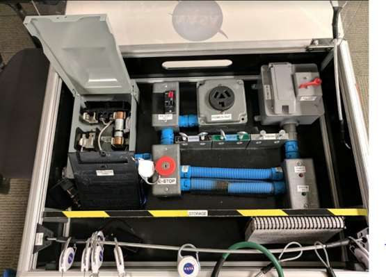
The biggest design challenge for the Informatics subsystem is working out how best to
interface with the human. What is the best design of robust, space-rated hardware that can
stand up to years of use in a demanding deep-space environment, while keeping an astronaut
safe? How do we best use emerging AR technologies to process and present data to a
spacewalker in effective and intuitive ways? Which spacesuit data are the right data to sense,
collect, and transmit? What will be the user experience of our future astronauts as they walk
across the surface of Mars? These are the questions that NASA is only beginning to answer,
and WE WANT YOUR HELP.
Test Objectives
The objective of the SUITS activity is to complete an EVA-simulated task while utilizing the
HoloLens as an aid to instruct the user. The task may require dexterity, physical activity, and
moving between various points within a room. A set of instructions are to be presented to the
user via the display environment (audibly, visually, etc.) in order to complete the task most
efficiently.
Initial Test Guidance
The test subject conducting the EVA will be standing in a room with access to an EVA
task board.
The test subject will be wearing gloves (to limit dexterity) and a tether belt.
One team member will be available as a support role during the EVA to read instructions
and act as Mission Control.
The test subject will be using a HoloLens during the EVA.
Any external tools or additions to the HoloLens test setup must be approved by NASA
points of contact.
Teams will use Unity and C# to program interfaces. As this is necessary for compatibility
with NASA provided data.
NASA will provide subsets of data for the interface. This data will include spacesuit and
biomedical data points, a set of instructions to complete the EVA tasks, and possibly
other items available for processing by the user interface.
The interface must be adaptable to multiple situations and sets of data.
The team will have a set amount of time prior to the competition to incorporate the
NASA data into the interface design.
Teams will run through a procedure with communication to “ground control” with a
specified latency with mission critical updates from ground control.
Test Scenario
Each student team will load their environment onto a HoloLens that will be worn by a test
subject. After starting the environment on the HoloLens, the test subject will run through a
procedure that involves completing a number of tasks. The procedure will include all the
necessary information to complete the tasks; however, the Informatics environments
developed by the student teams should aim to aid the test subject. The goal is to provide the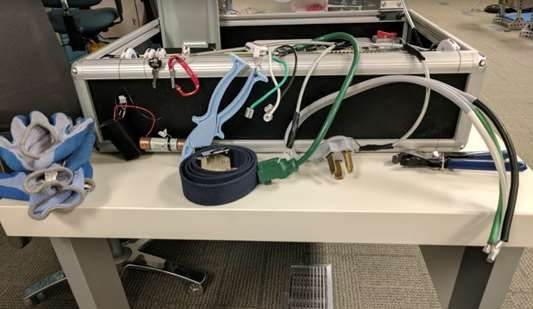
test subject information that makes them more efficient at completing a given task, without
becoming a distraction.
The following tasks may be completed as part of the procedure:
Providing suit information to ground control
o This will involve a person reporting to the subject to provide information about a
specific suit parameter. For instance, the question might be “What is your suit
pressure?” or “How much battery life do you have left?”
o The subject must be able to find this information in their display system, and
deliver the information to “ground control,” in this case, their partner.
Various tasks with the EVA task board
o Removing and reinstalling fuses with provided tools;
o Operating keys and unlocking locked cases;
o Installing cables into outlets with correct orientation
o Cable routing
Example Procedure Format:
1. Locate battery pack. Ensure that it is switched ON. Connect battery to load marked
BATTERY POWERED.
2. Notate and verbally record that the POWERED light is enabled and lit.
3. Locate the key in STORAGE labeled “BREAKER BOX.” Use BREAKER BOX key to open
compartment labeled “BREAKER BOX.”
These tasks are made to simulate an EVA as accurately as possible on Earth. As a result,
participants will be suited as such, wearing items such as bulky gloves or a tethered belt, for
example. Outside distractions, stressors, and lighting changes may also be introduced in order
to better simulate an EVA environment.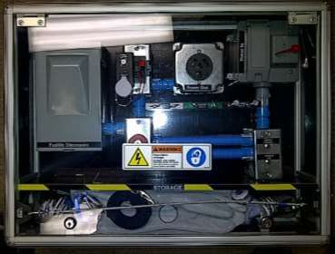
Figure 1. Shows the inside of an EVA taskboard. A similar grouping of tasks may need to be
                        completed when students showcase at JSC.

       Figure 2. Example of tools used to complete the tasks required in the EVAs.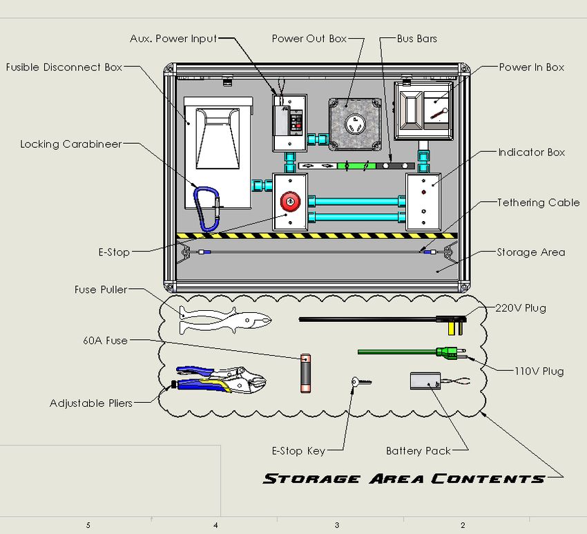
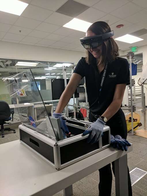
Figure 3. JSC intern Sarah Kuchel uses HoloLens as a guide to complete the EVA task.

NASA Testing Logistics
Once student teams arrive at JSC, they will participate in two test days during the five-day,
onsite experience.
   o Day One (No Testing): Arrivals, Welcomes, & Center and Facility Orientation
   o Day Two Testing: A test subject will wear a HoloLens loaded with the student team’s
        environment. The subject will then complete a variety of tasks while following a
        procedure. The goal for the student teams is to develop a display and auditory
        environment that aids the test subject in performing these tasks as efficiently and
        correctly as possible. The test subject will give student teams feedback on their displays
        and the teams will be given time to implement changes to their design if needed.
   o Day Three (No Testing): Optimizing design solutions
   o Day Four Testing: Another test subject will perform the same series of tasks with the
        team’s updated environments.
   o Day Five (No Testing): Wrap up activities and release
Program Deliverables Specific program deliverable requirements will be available via a separate document titled: NASA SUITS 2018 Proposal Guidelines. General team deliverables will include: o Proposal Reports o Project Schedule o Code and Custom Asset o Outreach Plan o Final Report
NASA EDUCATION EVA KIT-1

INTRODUCTION: Astronauts perform EVAs or Extravehicular Activities on the International
Space Station. To improve efficiency and safety, astronauts train for months. Each task is
scripted through what is called an EVA Checklist. These checklists are usually abbreviated and
printed onto a small Cuff Checklist that the astronaut wears during space walks as shown in
Figure 1. Below is the checklist for a simulated problem that an astronaut could encounter
during a spacewalk. Familiarize yourself with the problem, and when ready begin the exercise.
    Figure 1 Left: Checklist wrist cuff used by astronauts. Right: Mirrored wrist cuff used by astronauts.
                                          Courtesy of www.nasa.gov

.
                                   Figure 2 Air Scrubber panel simulator.
EVA Schematic and Storage Area Contents:
(All items must be tethered or securely fastened during EVA operations.)
Astronaut / EVA 1 Prep: Put on the EVA Belt and Gloves

CapCom Script: “EVA 1, this is Houston Mission Control. Please be advised, an
electrical short has damaged the power supply line to the Carbon Dioxide sensor on the
main air-scrubbing unit for the International Space Station. There is now a fault alarm
signaling and the air scrubbing unit is locked in the “OFF” status. This allows Carbon
Dioxide to overtake the smaller auxiliary air scrubbing units. You must reroute the
temporary battery supply power around the damaged circuit and then disable the alarm.
We are a go to proceed with the rerouting procedure. Please confirm you are a “GO” to
perform this procedure.
Disabling Alarm Procedure
1. On the RIGHT side of the EVA Kit, locate and use the
   PANEL ACCESS KEY to unlock the PANEL ACCESS DOOR
   LOCKS.
   CAUTION: The keys are on a tension-spring cable.
                                                              1.

2. Carefully return keys to the side of the EVA kit.

3. Insert your fingers in the CENTER OPENING and secure
   the PANEL ACCESS DOOR in an OPEN position.
   WARNING: Door can accidentally close.                      3.

4. On your belt, use the BLUE CARABINEER to securely
   tether to the TETHER CABLE inside the STORAGE.
   CAUTION: Notice the TETHER CABLE is adjustable
                                                              4.

5. Locate the E-STOP button and gently press down to
   temporarily disable the alarm.

                                                              5.
6. Locate the FUSIBLE DISCONNECT box and tether the
   BLUE CARABINEER to the TETHER CABLE.

7. Remove the BLUE CARABINEER from the FUSIBLE
   DISCONNECT box and transfer it to STORAGE.                 7.

8. Open the FUSIBLE DISCONNECT box and secure the lid
   in the open position.
   CAUTION: Pull the locking tab toward STORAGE with
   the index finger while lifting the cover with the thumb.   8.
9. Locate the BLACK DISCONNECT and tether it to the
TETHER CABLE.
10. Remove the DISCONNECT and place it in STORAGE.
CAUTION: Pull up with the index and middle fingers
while pushing down on the FUSE ACCESS PANEL with
the thumb.
10.
11. Tether the FUSE ACCESS PANEL to the TETHER CABLE.
12. Remove the FUSE ACCESS PANEL by pulling straight
up.
13. Place the FUSE ACCESS PANEL into STORAGE.
14. Tether the ALARM FUSE to the TETHER CABLE. 12.
15. In Storage, locate the BLUE FUSE PULLER.
16. Use the BLUE FUSE PULLER to remove ONLY the
ALARM FUSE.
CAUTION: Rock the ALARM FUSE with the FUSE
PULLER when pulling up.
17. Return the ALARM FUSE and the FUSE PULLER to
16.
STORAGE.18. In STORAGE, locate the FUSE ACCESS PANEL and
reinstall it into the FUSIBLE DISCONNECT box.
19. Remove the FUSE ACCESS PANEL tether from the
TETHER CABLE and stow inside.
WARNING: All tethers are under spring tension and
can retract quickly.
18.
20. In STORAGE, locate the DISCONNECT and reinstall it
into the FUSIBLE DISCONNECT box.
CAUTION: The DISCONNECT must read “ON” in the
upper right corner to restore conductivity.
21. Remove the DISCONNECT tether from the TETHER
CABLE.
WARNING: All tethers are under spring tension and
can retract quickly.
20.
22. Close the FUSIBLE DISCONNECT box cover.
23. In STORAGE, use the BLUE CARABINEER to clip and
lock the FUSIBLE DISCONNECT box cover.
24. Remove the BLUE CARABINEER’s tether from the
TETHER CABLE.
WARNING: All tethers are under spring tension and
can retract quickly.
23.
End Of Disabling
Alarm ProcedureRerouting Power Procedure
1. Locate the Aux. Power Input

2. Locate BATTERY PACK and tether to TETHER
   CABLE.

3. Undo the BATTERY PACK LEADS from the AUX.
   POWER INPUT.
   CAUTION: Depress the red and black plastic
   hammers on the side of the AUX. POWER INPUT
   and pull the leads straight up.

4. Remove BATTERY PACK from AUX. POWER
   INPUT.                                                  3.

5. Locate the ON/OFF switch on the back of the
   BATTERY PACK and switch it to the OFF position.

6. Place the BATTERY PACK into STORAGE.

7. In STORAGE, find the replacement BATTERY
   PACK.

8. Locate the ON/OFF switch on the back of the
   BATTERY PACK and switch it to the ON position.

9. Attach the replacement BATTERY PACK onto the      5.
   AUX. POWER INPUT by the Velcro.

10. Insert the BATTERY PACK leads back into same
    colored ports.
    CAUTION: Depress the red and black plastic
    hammers on the side of the AUX. POWER INPUT
    and push leads straight into their ports.

11. Conduct a GENTLE PULL TEST on the wires.

12. Remove the BATTERY PACK tether from the
    TETHER CABLE.
    WARNING: All tethers are under spring tension         12.
    and can retract quickly.

13. In STORAGE, locate the GRAY 220 Volt PLUG.

14. Install it into the POWER OUT.
CAUTION: Outlet and plug mate are stiff, ensure the full engagement of the plug into the outlet.
15. Locate the metal BUSS BAR and verify there are
    BLACK, GREEN & WHITE BUSSES, each with 2
    openings.

                                                         16.
16. Insert the WHITE 220 VOLT LEAD into the LEFT
    WHITE BUSS opening and GENTLY TIGHTEN the
    thumbscrew.
    CAUTION: DO NOT over tighten the thumbscrew.

17. Insert the GREEN 220 VOLT LEAD into the LEFT
    GREEN BUS opening.                                   17.
    CAUTION: DO NOT over tighten the thumbscrew.

18. Insert the BLACK 220 VOLT LEAD into the LEFT
    BLACK BUS opening.
    CAUTION: DO NOT over tighten the thumbscrew.
                                                         18.

19. Make sure the METAL LEADS are not sticking
    out the BACK of the BUSS BAR.

20. Conduct a Gentle PULL TEST on each cable.

21. In STORAGE, locate the 110 VOLT PLUG and
   install it into POWER IN.
   CAUTION: Lift cover with one hand while
   installing PLUG into the outlet with the other. The
   lid is spring-loaded.                                 21.
22. Insert the WHITE 110 VOLT PLUG LEAD into the
RIGHT WHITE BUS opening.
CAUTION: DO NOT over tighten the thumbscrew.
22.
23. Insert the GREEN 110 VOLT PLUG LEAD into the
RIGHT GREEN BUS opening.
CAUTION: DO NOT over tighten the thumbscrew.
23.
24. Insert the BLACK 110 VOLT PLUG LEAD into the
RIGHT BLACK BUS opening.
CAUTION: DO NOT over tighten the thumbscrew.
24.
25. Conduct a Gentle PULL TEST on each cable
26. In STORAGE, locate the E-STOP KEY.
25.
27. Insert the KEY into the E-STOP and TURN to the
RIGHT and the button will pop up.
26.
28. Remove the KEY and place it in STORAGE.29. Locate the AUX. POWER SWITCH on the
POWER IN box and switch it to the
“ON” position.
30. Can you please confirm YES or NO that
the SYSTEM GO indicator light is
GREEN?
31. IF GREEN, read this script:
28.
EVA 1, this is Houston Mission Control.
Congratulations. PHALCON is reporting
that they are reading a successful power
restoration on their console. You are a
go to untether from the TETHER CABLE
and return to space station. Mission
Control out.
32. IF NOT GREEN, read this script:
EVA 1, this is Houston Mission Control.
PHALCON confirms and is not able to report
a successful power restoration on their
console. EVA-1, please be advised that we
have prepared some trouble-shooting steps
for you to conduct on a future spacewalk.
Done.Clean up
1. Engage the E-Stop button
2. Disconnect all leads for the 110 Volt & 220 Volt Plug LEADS
3. Unplug the 110V & 220V PLUGS and stow the plugs in the STORAGE AREA
4. Switch the BATTERY PACKS switch to the “OFF” position
5. Ensure all remaining items are either installed securely or tethered in the STORAGE
AREA
6. Close the PANEL ACCESS DOOR and lock the door with the keys from the tethering belt
to secure the area
7. Return tethering belt and gloves to the instructor
Troubleshooting
PROBLEM REASON CHECK POINTS
Alarm sounds when AUX. POWER The wrong fuse was removed. Replace the fuse that was taken out and remove the
SWITCH is switched on. ALARM FUSE.
Nothing happens when AUX. There is no power going to the circuit. -BATTERY PACK is switched "OFF"
POWER SWITCH is switched on. -BATTERY PACK leads are not inserted into their ports
-220V PLUG or leads where not installed correctly
-110V PLUG or leads where not installed correctly
-AUX. POWER SWITCH is in the "OFF" position
-E-STOP is still engaged
-Batteries in the BATTERY PACK are depletedYou can also read