HMI-Link G2 Device PC 301-E12 - Operating Manual - Sigmatek
←
→
Page content transcription
If your browser does not render page correctly, please read the page content below

HMI-Link G2
               Device
                               PC 301-E12

                               Operating Manual

Date of creation: 04.06.2020     Version date: 06.08.2020   Article number: 01-310-301-E12-E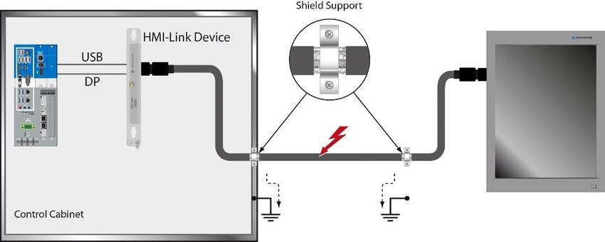
Publisher: SIGMATEK GmbH & Co KG
                                   A-5112 Lamprechtshausen
                                      Tel.: +43/6274/4321
                                    Fax: +43/6274/4321-18
                                   Email: office@sigmatek.at
                               WWW.SIGMATEK-AUTOMATION.COM

                                               Copyright © 2020
                                            SIGMATEK GmbH & Co KG

                                       Translation from German

All rights reserved. No part of this work may be reproduced, edited using an electronic system, duplicated or dis-
tributed in any form (print, photocopy, microfilm or in any other process) without express permission.

We reserve the right to make changes in the content without notice. SIGMATEK GmbH & Co KG is not responsible for
technical or printing errors in this handbook and assumes no responsibility for damages that occur through its use.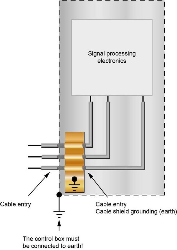
HMI-LINK G2 DEVICE            PC 301-E12

HMI-Link G2 Device                                              PC 301-E12

Using HMI-Link G2 Device allows HMI-Link G2 display units to be connected with a
SIGMATEK IPC. This allows the transmission of USB and display signals up to 100 m.

06.08.2020                                                                 Page 1
PC 301-E12              HMI-LINK G2 DEVICE

Contents
1    Introduction ............................................................................. 5
     1.1         Target Group/Purpose of this Operating Manual ...................... 5

     1.2         Important Reference Documentation ......................................... 5

     1.3         Contents of Delivery ..................................................................... 5

2    Basic Safety Guidelines ......................................................... 6
     2.1         Symbols Used ............................................................................... 6

     2.2         Disclaimer ...................................................................................... 8

     2.3         General Safety Guidelines ........................................................... 9

3    Norms and Guidelines ...........................................................10
     3.1         Guidelines.................................................................................... 10
         3.1.1        EU Declaration of Conformity ............................................................ 10

4    Technical Data .......................................................................11
     4.1         Performance Data ....................................................................... 11

     4.2         Electrical Requirements ............................................................. 11

     4.3         Environmental Conditions ......................................................... 12

     4.4         Miscellaneous ............................................................................. 12

5    Mechanical Dimensions ........................................................13

6    Connector Layout ..................................................................14
     6.1         X1: Display port IN ...................................................................... 15

     6.2         X2: USB 2.0 IN (Type B) .............................................................. 15

Page 2                                                                                               06.08.2020
HMI-LINK G2 DEVICE PC 301-E12
6.3 X3: HMI Local OUT (HMI-Link G2, Mini-I/O) .............................. 16
6.4 X4 Supply voltage ....................................................................... 16
6.4.1 Applicable Connectors ...................................................................... 16
7 Status Displays...................................................................... 17
8 Assembly/Installation ........................................................... 18
8.1 Check Contents of Delivery ....................................................... 18
8.2 Mounting Instructions ................................................................ 18
8.3 Installation ................................................................................... 19
8.4 Mounting Material ....................................................................... 19
8.5 Minimum Clearance to the Next Components ......................... 20
9 Wiring Guidelines .................................................................. 21
9.1 Ground ......................................................................................... 21
9.2 Shielding ...................................................................................... 22
9.3 ESD Protection ............................................................................ 22
10 HMI-Link G2 Wiring ............................................................... 23
10.1 Shielding ...................................................................................... 23
10.2 HMI-Link G2 Cable Specification............................................... 24
10.2.1 Tyco Mini I/O Pin Assignment ........................................................... 24
10.3 HMI-Link G2 Cable Routing ....................................................... 24
11 Transport/Storage ................................................................. 25
12 Maintenance........................................................................... 26
06.08.2020 Page 3PC 301-E12 HMI-LINK G2 DEVICE
12.1 Service ......................................................................................... 26
12.2 Repair ........................................................................................... 26
13 Disposal ..................................................................................27
Page 4 06.08.2020HMI-LINK G2 DEVICE PC 301-E12
1 Introduction
1.1 Target Group/Purpose of this Operating Manual
This operating manual contains all information required to operate this product.
This operating manual is intended for:
• Project planners
• Technicians
• Commissioning engineers
• Machine operators
• Maintenance/test technicians
General knowledge of automation technology is required.
Further help and training information, as well as the appropriate accessories can be found on
our website www.sigmatek-automation.com
Our support team is happily available to answer your questions.
Please see our website for our hotline number and business hours.
1.2 Important Reference Documentation
This and additional documents can be downloaded from our website or obtained through
SIGMATEK Support.
1.3 Contents of Delivery
1x HMI-Link G2 Device PC 301-E12
06.08.2020 Page 5PC 301-E12 HMI-LINK G2 DEVICE
2 Basic Safety Guidelines
2.1 Symbols Used
The following symbols are used in the operator documentation for warning and danger mes-
sages, as well as informational notes:
DANGER Danger indicates that death or serious injury will occur, if the specified
measures are not taken.
To avoid death or serious injuries, observe the all guidelines.
Danger indique une situation dangereuse qui, faute de prendre les
mesures adéquates, entraînera des blessures graves, voire mortelles.
Respectez toutes les consignes pour éviter des blessures graves,
voire mortelles.
WARNING Warning indicates that death or serious injury can occur, if the specified
measures are not taken.
To avoid death or serious injuries, observe the all guidelines.
Avertissement d’une situation dangereuse qui, faute de prendre les
mesures adéquates, entraînera des blessures graves, voire mortelles.
Respectez toutes les consignes pour éviter des blessures graves,
voire mortelles.
CAUTION Caution indicates that moderate to slight injury can occur, if the specified
measures are not taken.
To avoid moderate to slight injuries, observe the all guidelines.
Attention indique une situation dangereuse qui, faute de prendre les
mesures adéquates, peut entraîner des blessures assez graves ou lé-
gères.
Respectez toutes les consignes pour éviter des blessures graves,
voire mortelles.
INFORMATION
Provides important information on the product, handling or relevant sections
of the documentation, which require attention.
Page 6 06.08.2020HMI-LINK G2 DEVICE PC 301-E12
Danger for ESD-sensitive components. Les signes de danger pour les com-
posants sensibles aux décharges électrostatiques.
06.08.2020 Page 7PC 301-E12 HMI-LINK G2 DEVICE
2.2 Disclaimer
The contents of this operating manual were prepared with the greatest care.
However, deviations cannot be ruled out. This operating manual is regularly
checked and required corrections are included in the subsequent versions.
The machine manufacturer is responsible for the proper assembly, as well
as device configuration. The machine operator is responsible for safe han-
dling, as well as proper operation.
The current operating manual can be found on our website. If necessary,
contact our support.
Subject to technical changes, which improve the performance of the devices.
The following operating manual is purely a product description. It does not
guarantee properties under the warranty.
Please thoroughly read the corresponding documentation and this operating
manual before handling a product.
SIGMATEK GmbH & Co KG is not liable for damages caused through
non-compliance with these instructions or applicable regulations.
Page 8 06.08.2020HMI-LINK G2 DEVICE PC 301-E12
2.3 General Safety Guidelines
The safety guidelines in the other sections of this operating manual must be observed. These
instructions are visually emphasized by symbols.
According to EU Guidelines, the operating instructions are a component of a
product.
This operating manual must therefore be accessible in the vicinity of the ma-
chine since it contains important instructions.
This operating manual should be included in the sale, rental or transfer of the
product, or its online availability indicated.
Maintain this operating manual in readable condition and keep it accessible
for reference.
Regarding the requirements for Safety and health connected to the use of
machines, the manufacturer must perform a risk assessment in accordance
with machine guidelines 2006/42/EG before introducing a machine to the
market.
Before commissioning this product, check that conformance with the provi-
sions of the 2006/42/EG guidelines is correct. As long as the machine with
which the product should be used does not comply with the guideline, oper-
ating this product is prohibited.
Operate the unit with devices and accessories approved by SIGMATEK only.
CAUTION Handle the device with care and do not drop or let fall.
Prevent foreign bodies and fluids from entering the device.
The device must not be opened, otherwise it could be damaged!
The module complies with EN 61131-2.
In combination with a machine, the machine builder must comply with EN
60204-1 standards.
For your own safety and that of others, compliance with the environmental
conditions is essential.
The control cabinet must be connected to ground correctly.
To perform maintenance or repairs, disconnect the system from the power
supply.
06.08.2020 Page 9PC 301-E12 HMI-LINK G2 DEVICE
3 Norms and Guidelines
3.1 Guidelines
The product was constructed in compliance with the following European Union guidelines
and tested for conformity.
3.1.1 EU Declaration of Conformity
EU Declaration of Conformity
The product HMI-Link G2 Device PC 301 E12 conforms to the following Eu-
ropean guidelines:
• 2014/35/EG Low-voltage guideline
• 2014/30/EU “Electromagnetic Compatibility” (EMC guideline)
• 2011/65/EU “Restricted use of certain hazardous substances in
electrical and electronic equipment” (RoHS Guideline)
The EU Conformity Declarations are provided on the SIGMATEK website.
See Products/Downloads or use the search function and the keyword “EU
Declaration of Conformity”.
Page 10 06.08.2020HMI-LINK G2 DEVICE PC 301-E12
4 Technical Data
4.1 Performance Data
Interfaces 1x HMI Local OUT (HMI-Link G2)
1x USB 2.0 (Type B) IN
1x DisplayPort IN
In order to use the HMI-Link, a second-generation SIGMATEK HMI-Link (G2)
display unit is required on the remote station.
4.2 Electrical Requirements
Supply voltage typically +24 V DC ±20 % (SELV/PELV)
Supply voltage (UL) +24 V DC ±20 % (NEC Class 2 or LVLC) (1)
Current consumption at 24 V maximum 170 mA
DC
(1) For USA and Canada:
The supply must be limited to:
a) max. 5 A at voltages from 0-20 V DC, or
b) 100 W at voltages from 20-60 V DC.
The limiting component (e.g. transformer, power supply or fuse) must be certified by an NRTL
(Nationally Recognized Testing Laboratory).
06.08.2020 Page 11PC 301-E12 HMI-LINK G2 DEVICE
4.3 Environmental Conditions
Storage temperature -20 ... +60°C
Environmental temperature 0 ... +50°C
Humidity 10-95 %, non-condensing
Installation altitude above sea 0-2000 m without derating
level
> 2000 m up to a maximum of 5000 m with derating of the maximum envi-
ronmental temperature by 0.5 °C per 100 m
Operating conditions pollution degree 2
EMC resistance in accordance with EN 61000-6-2 (industrial area)
EMC noise generation in accordance with EN 61000-6-4 (industrial area)
Vibration resistance EN 60068-2-6 2-9 Hz amplitude 3.5 mm
9-200 Hz 1 g (10 m/s²)
Shock resistance EN 60068-2-27 15 g (150 m/s²)
Protection type EN 60529 IP20
4.4 Miscellaneous
Article number 01-310-301-E12
Hardware version 1.x
Approvals CE, UL in preparation
Page 12 06.08.2020HMI-LINK G2 DEVICE PC 301-E12
5 Mechanical Dimensions
Dimensions 25 x 204.5 x 83 mm (W x H x D)
Material housing: Aluminum anodized Natural C0
Weight 0.20 kg
06.08.2020 Page 13PC 301-E12 HMI-LINK G2 DEVICE
6 Connector Layout
top
bottom
Front View
Page 14 06.08.2020HMI-LINK G2 DEVICE PC 301-E12
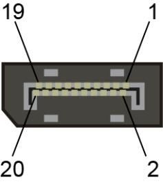
6.1 X1: Display port IN
Pin Function
1 n.c.
2 GND
3 n.c.
4 n.c.
5 GND
6 n.c.
7 Lane 1 (n)
8 GND
9 Lane 1 (p)
10 Lane 0 (n)
11 GND
12 Lane 0 (p)
13 Config1
14 Config2
15 AUX CH (p)
16 GND
17 AUX CH (n)
18 Hot Plug
19 Return
20 n.c.
n.c. = do not use
The respective display resolution is transmitted via AUX CH (p) and AUX CH
(n) per i2C protocol.
6.2 X2: USB 2.0 IN (Type B)
Pin Function
1 +5 V
2 D0-
3 D0+
4 GND
06.08.2020 Page 15PC 301-E12 HMI-LINK G2 DEVICE
6.3 X3: HMI Local OUT (HMI-Link G2, Mini-I/O)
Pin Function
1 HMI_P0
2 HMI_N0
3 HMI_P1
4 HMI_P2
5 HMI_N2
6 HMI_N1
7 HMI_P3
8 HMI_N3
6.4 X4 Supply voltage
Pin Function
1 +24 V
2 +24 V
3 GND
4 GND
6.4.1 Applicable Connectors
USB: Type B
Display port: 20-pin display port connector
HMI-Link: 8-pin Tyco Mini I/O Type 1
Supply voltage Phoenix Contact FK-FMC 1.5/ 4-ST-3.5
Page 16 06.08.2020HMI-LINK G2 DEVICE PC 301-E12
7 Status Displays
LED 1 red ON No HMI-Link connection between PC and terminal
LED 2 yellow OFF Check HMI-Link cable
LED 3 green OFF
LED 1 red OFF HMI-Link connection between PC and terminal available
LED 2 yellow ON No video signal available
LED 3 green OFF Check display port cable
LED 1 red ON HMI-Link connection between PC and terminal available
LED 2 yellow OFF Video signal available
LED 3 green ON No USB signal
Check USB cable
LED 1 red OFF HMI-Link connection between PC and terminal available
LED 2 yellow ON Video signal available
LED 3 green ON No valid EDID data (1)
Restart PC and terminal
LED 1 red OFF System ready
LED 2 yellow OFF
LED 3 green ON
(1)EDID data (Extended Display Identification Data) contain exact information for the installed
display. Using this data, the control of the display is configured at the signal source (e.g.:
SIGMATEK IPC).
06.08.2020 Page 17PC 301-E12 HMI-LINK G2 DEVICE
8 Assembly/Installation
8.1 Check Contents of Delivery
Ensure that the contents of the delivery are complete and intact. See chapter 1.3Contents of
Delivery for more information.
On receipt and before initial use, check the device for damage. If the device
is damaged, contact our customer service and do not install the device in
your system.
Damaged components can disrupt or damage the system.
8.2 Mounting Instructions
The HMI-Link G2 Device has 2 mounting holes for installation onto the back wall of the control
cabinet. This is the preferred mounting position since the cool air can flow from the bottom to
the top of the module for optimal cooling.
Page 18 06.08.2020HMI-LINK G2 DEVICE PC 301-E12 8.3 Installation A different mounting position is not recommended, as the specified environmental tempera- ture cannot be guaranteed. 8.4 Mounting Material • 2 x M5 screws • 2x M5 washers (EN ISO 7089-5-200HV) 06.08.2020 Page 19
PC 301-E12       HMI-LINK G2 DEVICE

8.5   Minimum Clearance to the Next Components

Page 20                                          06.08.2020
HMI-LINK G2 DEVICE               PC 301-E12

9     Wiring Guidelines
9.1    Ground
The signal-processing electronics must be connected to ground via the mount on control
cabinet or over the ground terminal provided. It is important to create a low-ohm ground con-
nection, only then can error-free operation be guaranteed. The ground connection must be
made with the maximum cross section and largest (electrical) surface possible.

Any noise signals that reach the signal-processing electronics over external cables must be
filtered through the ground connection. High frequency noise can also be dissipated over a
large (electrical) surface (skin effect).

06.08.2020                                                                          Page 21
PC 301-E12              HMI-LINK G2 DEVICE

9.2    Shielding
The wiring of all data lines must be shielded. The low-ohm shielding is either connected at
the entry to the control cabinet or directly before the device over a large surface (cable grom-
mets, grounding clamps)!

Noise signals can therefore be prevented from reaching the electronics and affecting the
function.

9.3    ESD Protection

               Before any device is connected to, or disconnected from the product, the
               potential should be equalized (by touching the control cabinet or ground ter-
               minal). Electrostatic loads (through clothing and shoes, etc.) can thereby be
               dissipated.

Page 22                                                                             06.08.2020
HMI-LINK G2 DEVICE PC 301-E12 10 HMI-Link G2 Wiring 10.1 Shielding The cable shielding must be connected to ground on both sides to prevent noise signals from reaching the electronics and affecting the function. 06.08.2020 Page 23
PC 301-E12              HMI-LINK G2 DEVICE

10.2 HMI-Link G2 Cable Specification
For the HMI-Link G2 line, CAT5e or CAT6 cables with shielded connectors must be used.

Self-fabricated cables must be tested for compliance with the limit values corresponding to
the cable class (CAT5e/CAT6...).

The HMI-Link G2 cable must be wired 1:1. A Tyco Mini I/O Type 1 connector plug must be
used.

10.2.1    Tyco Mini I/O Pin Assignment

                                 Pin              Wire Color                Signal
                                  1               White/green               HMI_P0
                                  2                  green                  HMI_N0
                                  3               White/orange              HMI_P1
                                  4                   blue                  HMI_P2
                                  5                White/blue               HMI_N2
                                  6                 Orange                  HMI_N1
                                  7               White/brown               HMI_P3
                                  8                  Brown                  HMI_N3
                                shield           Cable shielding             shield

10.3 HMI-Link G2 Cable Routing

For CAT5e cables, the total allowable length is limited to 90 m. To utilize the maximum 100
m length of the HMI-Link G2, at least, CAT6 cable must be used.

To ensure correct function, it is important to ensure that in the cable strand, the wires do not
run parallel over long distances. It is recommended that a cable equivalent to or better than
the CAT6A standard be used.

When multiple HMI-Link cables run in parallel, the following limit values for the maximum
length of the parallel wiring apply:

                           Cable type    30 m   50 m    70 m       100 m
                           CAT5e/CAT6      6      4       2          1
                           CAT6a/CAT7      6      6       6          6

These specifications must be observed to avoid crosstalk between the data lines (and the
resulting interference).

Page 24                                                                               06.08.2020
HMI-LINK G2 DEVICE PC 301-E12
11 Transport/Storage
This device contains sensitive electronics. During transport and storage, high
mechanical stress must therefore be avoided.
For storage and transport, the same values for humidity and vibration as for
operation must be maintained!
During transport, temperature and humidity fluctuations may occur. Ensure
that no moisture condenses within or on the device be letting the device cli-
matize to the room temperature while turned off.
06.08.2020 Page 25PC 301-E12 HMI-LINK G2 DEVICE
12 Maintenance
During maintenance as well as servicing, observe the safety instructions from
chapter 2.
12.1 Service
This product was constructed for low-maintenance operation.
12.2 Repair
When sent for repair, the panel should be transported in the original packag-
ing if possible. Otherwise packaging should be selected that sufficiently pro-
tects the product from external mechanical influences, such as cardboard
filled with air cushioning.
In the event of a defect/repair, send the panel with a detailed error description to the address
listed at the beginning of this document.
Page 26 06.08.2020HMI-LINK G2 DEVICE PC 301-E12
13 Disposal
Should you need to dispose of the device, the national electronic
scrap regulation must be observed.
The panel cannot be discarded with domestic waste.
06.08.2020 Page 27PC 301-E12 HMI-LINK G2 DEVICE Documentation Changes Change date Affected page(s) Chapter Note 06.08.2020 Document General redesign Page 28 06.08.2020
You can also read