The forces acting on the teeth of catching machine - E3S Web ...
←
→
Page content transcription
If your browser does not render page correctly, please read the page content below
E3S Web of Conferences 274, 03009 (2021) https://doi.org/10.1051/e3sconf/202127403009
STCCE – 2021
The forces acting on the teeth of catching
machine
Rustam Ergashev1, Fakhriddin Bekchanov1, Jaloliddin Rashidov1[0000-0001-5593-9232], and
Boybek Kholbutaev2
1Tashkent Institute of Irrigation and Agricultural Mechanization Engineers, 100000 Tashkent, Uzbekistan
2Jizzakh Polytechnic Institute, 130100 Jizzakh, Uzbekistan
Abstract. Republic of Uzbekistan, pumping stations are used in very difficult
conditions. The presence of various particles and effluents in the water has a
negative effect on the operating modes of the pumping equipment. Special
grilles are installed to prevent the catching devices from entering the advance
chamber of the pump station. The shape and length of the device covers are
of great importance so that they are caught in front of the grilles and
completely cover the accumulated debris. In the article, the laws of mechanics
were used to determine the shape and size of the working device of the device
for cleaning the effluent flowing into the pump station as water and
accumulated in front of the grids. In doing so, the condition of ensuring
complete removal of the leaks covered by the device was taken into account.
It was argued that the angle γ between the working surfaces and velocities of
the covers should be less than 90-φ over its entire working surface in order to
fully cover the device shafts. It was found that when the working surface of
the device is flat, the time of interaction with the catching device pieces is
minimal. Studies and literature have shown that the angle of friction on the
working surfaces of the device covers should be φ=20о, the angle between
the working surface of the device cover and the rotational speed γ=70о.
Keywords. Pump station, fore chamber, cage, mouth, device, suction pipe,
cavitation.
1 Introduction
Extremely turbid water in the country's sources, parts of pumping units that carry water,
including bodies, substances, effluents, including impellers, fail mainly due to mechanical
effects and cavitation erosion [1, 2]. It is necessary to ensure the geodetic suction height of
the water level in the avant-garde to prevent cavitation erosion that occurs on the working
blades of the pump unit. In cases where the water is clean and flows at the same flow rate
without obstruction, the suction height in the vane chamber can be ensured [3-5]. Russian
Scientists from the Siberian State Technological University, V.P. Korpachev and A.I.
Perezhilin, studied the causes of water pollution in hydropower plants and recommended that
reservoirs should be kept clean, mainly due to leakage of water from the shores [6].
In 2016-2020, research work showed that on the Amu-Bukhara canal, the Karshi main canal,
Corresponding author: erustamrah@mail.ru
© The Authors, published by EDP Sciences. This is an open access article distributed under the terms of the Creative Commons
Attribution License 4.0 (http://creativecommons.org/licenses/by/4.0/).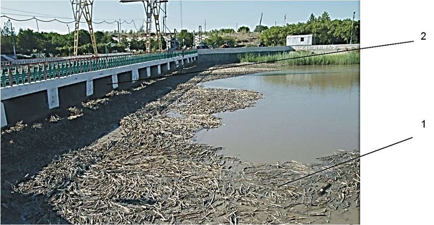
E3S Web of Conferences 274, 03009 (2021) https://doi.org/10.1051/e3sconf/202127403009
STCCE – 2021
the drop in water level in the avalanche occurred as a result of changes in water consumption in
the Amudarya, the muddy filling of canals and the formation of artificial barriers [7, 8].
The change in the period and volume of discharge of effluents from the Amudarya to the
pumping stations depends on the following [9]:
- at the beginning of the irrigation season to the time of the first supply of water to the
pump station;
- the amount of tree stems, roots, which are washed away due to the increase in water
consumption in the river, the water changes its course and flows with it;
- the type of waste generated by industrial, manufacturing and domestic organizations
located along rivers and canals;
- due to the location of pastures and meadows along the coast, the animals can
accidentally fall, drown and flow to the pumping stations.
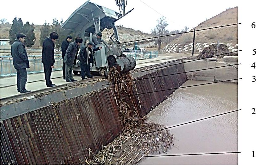
Fences have been installed in the Amu-Bukhara-1 and Amu-Bukhara-2 car canals to trap
water leaks and prevent it from entering the pumping station (Fig. 1).
Fig. 1. The process of removing debris collected in front of the grate at the pump station Amu-Bukhara-1:
1 – mouth; 2 – grid holding traps; 3 – streams falling back into channel; 4 – car moving rails; 5 – dryer
cover; 6 – the machine that moves the cleaning device.
The different nebulae of the runoff, the rapid change in size throughout the year, and the
erratic flow in different directions cause the water to accumulate in front of the installed
fences and block the waterway (Fig. 2).
Fig. 2. Collection of effluents in front of the grate at the Amu-Bukhara-2 pumping station: 1 – mineral
and organic particles; 2 – water access paths to the forechamber.
2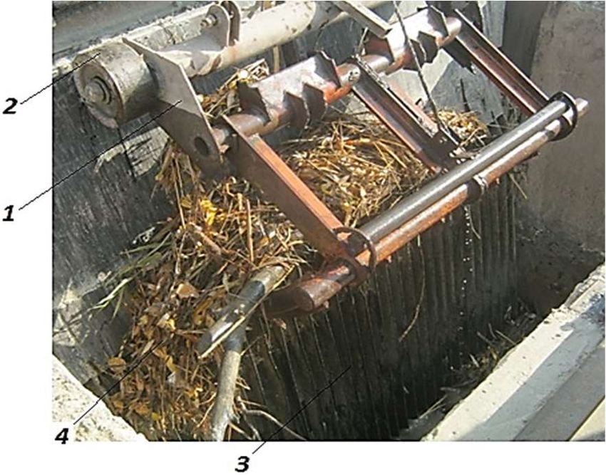
E3S Web of Conferences 274, 03009 (2021)                              https://doi.org/10.1051/e3sconf/202127403009
STCCE – 2021

         At the Amu-Bukhara-1 and Amu-Bukhara-2 pumping stations, one of the main reasons for
     the drop in the water level in the vane chamber was the failure of the device to fully meet the
     requirements [10, 11]. As a result of untimely cleaning of the gutters in front of the fences installed
     in front of the van, the water became stagnant, which led to a drop in the water level in the van.
         A drop in the water level in the vane chamber creates water clusters in front of the suction
     pipes, which leads to the absorption of air into the pump and a decrease in performance [12, 13].
         Therefore, the improvement of the technology of cleaning and removal of debris is one
     of the important issues. The aim of the study was to substantiate the parameters of the device
     workstation, which provides for the cleaning and removal of debris accumulated in front of
     the grilles (Fig. 3). The following issues have been resolved to achieve this goal:
         - to determine the forces acting on the device covers to ensure that the debris accumulated
     in front of the grille is completely covered and removed;
         - to determine the shape of the cover to ensure complete removal and removal of debris
     that has accumulated in front of the grilles [14].

     Fig. 3. The process of covering the mouths: 1 – device base; 2 – device base wheels; 3 – grid holding traps;
     4 – a set of mouthpieces with different contents.

     2 Method
     The forces acting on it were determined using the laws of mechanics to determine the shape
     and size of the work piece of the device that cleans the debris that flows into the pump station
     avanker along with the water and accumulates in front of the grilles. In doing so, the condition
     of ensuring complete removal of the leaks covered by the device was taken into account.

     3 Results and discussion
     The shape and length of the device covers are of great importance so that they are caught in
     front of the grilles and completely cover the accumulated debris. To ensure that the lugs that
     have accumulated in front of the grilles are completely covered and cleaned, we will first
     consider the forces acting on the lugs by the device lining. During the process of covering
     the device shafts, its M part is affected by normal N and frictional forces F by the device
     cover (Fig. 4). We divide the normal force N acting on the M part of the catching device into
     two influences: the device velocity Vм in the process of covering the catching devices, i.e.,
     Nv directed along its rotation speed relative to point 0, and Nτ directed along the working
     surface of the catching device [15-19]:
                                            Nτ = Nctg γ                                      (1)

                                                          3
E3S Web of Conferences 274, 03009 (2021) https://doi.org/10.1051/e3sconf/202127403009
STCCE – 2021
and
N
Nv , (2)
sin
where γ is the angle between the working surface of the device cover and the rotational speed
Vм. For the catching devices to be completely covered by the device cover, the force Nτ must
be greater than the friction force F, i.e.
Nτ > F. (3)
Fig. 4. A diagram of the forces acting on the parts of the mouthpiece by the cover of the device cover.
This is because only when this condition is met is it ensured that the catching devices are
pushed upwards along the covers of the device cover, which are completely covered by the
device. (3) Substituting the value of Nt in the expression (1) and taking into account that
F = fN = N tg φ (where f, ph is the coefficient of friction and angle of friction on the working
surfaces of the device covers, respectively, we obtain the following result:
Nctg γ > Ntg φ. (4)
We solve this expression with respect to τ:
γ > 90 – φ. (5)
Hence, in order to fully cover the device surfaces, the angle γ between the working
surfaces and velocities of the device covers must be less than 90-φ over its entire working
surface, i.e., condition (5) must be met. We now move on to justify the shape of the working
surfaces of the device cover covers. In solving this problem, we proceed from the condition
that the time of interaction between the working surface of the cover and the parts of the
mouth is minimal [20-29]. This is due to the fact that, firstly, the sheets are easily moved
along the working surface, and secondly, the technological process is carried out with
minimal energy consumption. Let us consider the motion of the axial segments in the ZOX
coordinate system (where the OX axis is horizontal and the OZ axis is perpendicular) under
the influence of the coverage, whose working surface has an arbitrary curved shape (Fig. 5).
Fig. 5. The shape of the working surfaces of the device covers justification scheme.
4E3S Web of Conferences 274, 03009 (2021) https://doi.org/10.1051/e3sconf/202127403009
STCCE – 2021
In this coordinate system, the axial fragments rotate under the influence of the normal N
and friction forces acting on them, Vм, and the relative sliding motion Vc with velocity along
the working surfaces of the overlaps [1-2].
It is directed along the force R, which is an equal effect of the forces F.
In this case, the absolute velocity of the axial fragments Va is equal to the geometric sum
of the velocities Vm and the relative Vc velocities, i.e. Va Vм2 Vc2 2VмVc cos and N and it
is directed along the force R, which is an equal effect of the forces F. Using the scheme shown
in Fig. 5, we express the velocity Vc in terms of velocity Vm and determine the slip time t from
point 0 (0.0) to the point A (x1, z1) of the working surface of the device cover of the slice M:
cos( )
Vc Vм Vм (cos sin tg ); (6)
cos
X1 X
dx 2 dz 2 1
1 ( z) 2
t
0
Vc
0 м
V (cos sin tg )
dx. (7)
Assuming that the device covers are oriented Vm horizontally in the process of covering
the gaps, we express the sing and cosg in expression (7) by dx and dz:
dz z
sin (8)
2
dx dz 2
1 ( z ) 2
and
dz 1
cos . (9)
2 2
dx dz 1 ( z) 2
Given these expressions, expression (7) has the following appearance:
х
1 1 1 ( z)2
Vм 0 1 ztg
t dx. (10)
We examine this expression to the extremum under the following condition:
d
( Fz Fz ) 0, (11)
dx
where Fz’ and Fz are specific derivatives of the function F on z’ and z, respectively;
F – (11) function under the integral of the expression.
(11) function under the integral according to the expression:
1 ( z ) 2
F . (12)
1 z tg
It can be seen from this expression that the function F does not depend on z. Therefore,
expression (11) has the following appearance:
d
Fz 0 (13)
dx
To fulfill this condition should be:
дF d
Fz const ; Fz 0 (14)
дz dx
Because only then the condition is fulfilled. Taking a special derivative of z’ from
expression (12), we obtain the following.
дF 2 z ' (1 z ' tg ) [1 ( z ' ) 2 ]tg
. (15)
дz ( 2 z ' tg ) 2
5E3S Web of Conferences 274, 03009 (2021) https://doi.org/10.1051/e3sconf/202127403009
STCCE – 2021
According to the expression (14), this expression must have a constant size, as such where
C is a constant quantity:
2 z ' (1 z ' tg ) [1 ( z ' ) 2 ]tg
С, (16)
(2 z ' tg ) 2
decomposing the expression (16) with respect to z, it is generally written as follows:
z’ = f(φ) = const. (17)
This expression indicates that in order for t to have an extreme value, z’ = const the device
cover must have a flat working surface, as only that is ensured.
When the working surface of the device covers is flat (7), the expression will have the
following appearance:
Т
t , (18)
Vм (cos sin tg )
where lT is the length of the working surfaces of the device covers.
Therefore, based on the above, it can be said that in order to ensure the quality of the
technological process at the required level with low energy consumption, the working surface
of the device cover should be in the form of a flat surface installed at an angle of less than
90-φ to the horizon.
In our study and in the literature, it was found that when the φ=20о is, the expression (5)
should be γ =70о.
4 Conclusion
The presence of various particles and effluents in the water adversely affects the operating
modes of the pumping equipment. Special grids will be installed in the channel to prevent the
contents of the water from entering the advance chamber of the pump station. The shape and
length of the device covers are of great importance so that they are caught in front of the grilles
and completely cover the accumulated debris. The correct selection of the shape and size of the
workpiece ensures complete removal of the catching devices covered by the device. When the
angle g between the working surfaces and velocities of the device covers is less than 90-φ over
its entire working surface, it is theoretically justified that the gaps accumulated in front of the
grids are completely covered. One of the main conditions is that full coverage and cleaning
is ensured when the interaction time of the catching device set with the device cover, where
the working surface is flat, is minimal. Studies and literature have shown that the angle of
friction between the working surfaces of the device covers should be φ=20о, the angle
between the working surface of the device cover and the rotational speed γ=70о.
References
1. M. Mamajonov, D.R. Bazarov, B.R. Uralov, G.U. Djumabaeva, N. Rahmatov. The impact
of hydro-wear parts of pumps for operational efficiency of the pumping station, Journal
of Physics: Conference Series 1425, 012123 (2019). DOI: 10.1088/1742-6596/1425/1/
012123.
2. D. Bazarov, N. Vatin, O. Bakhtiyor, V. Oybek. Hydrodynamic effects of the flow on the
slab of the stand in the presence of cavitation, IOP Conference Series: Materials Science
and Engineering 1030, 012110 (2021). DOI: 10.1088/1757-899X/1030/1/012116.
3. Dilshod Bazarov, Irina Markova, B.N., O.V. Hydraulic aspects of the layout of head
structures during water intake from lowland rivers, IOP Conference Science, Materials
1015, 012041 (2021). DOI: 10.1088/1757-899X/1015/1/012041.
6E3S Web of Conferences 274, 03009 (2021) https://doi.org/10.1051/e3sconf/202127403009
STCCE – 2021
4. O. Glovatsky, R. Ergashev, A. Saparov, M. Berdiev, B. Shodiev. Cavitation-abrasive
wear working collectors of pumps, IOP Conference Series: Materials Science and
Engineering 869 (4), 042006 (2020).
5. J. Rashidov, B. Kholbutaev. Water distribution on machine canals trace cascade of
pumping stations, IOP Conf. Ser. Mater. Sci. Eng. 883, (2020).
6. O. Glovatsky, R. Ergashev, A. Saparov, M. Berdiev, B. Shodiev. Cavitation-abrasive
wear working collectors of pumps, IOP Conference Series: Materials Science and
Engineering, (2020).
7. V.P. Korpachev, A.I. Perezhilin. Zagryazneniye i zasoreniye vodokhranilishch GES
drevesno-kustarnikovoy rastitel'nost'yu, organicheskimi veshchestvami i vliyaniye ikh na
kachestvo vody: monografiya Rossiyskoy Akademii Yestestvoznaniya, 148 (2010).
8. O.Ya. Glovatskii. Operating experience and reliability assessment of elements of
pumping stations, Hydrotechnical Construction 23 (9), 532-537 (1989).
9. S. Song, G. Sang, L. Zhang, W. Wang. Study on the Hydraulic Characteristics of Cascade
Pumping Station on the East Route of South-to-North Water Diversion Project, IOP
Conference Series: Earth and Environmental Science 170, (2018).
10. R. Ergashev, F. Artikbekova, G. Jumabayeva, F. Uljayev. Problems of water lifting
machine systems control in the republic of Uzbekistan with new innovation technology,
E3S Web of Conferences, (2019).
11. S.I. Basok, Ji.A. Kamyshentsev, I.V. Kononov, Yu.V. Sokolov, V.M. Aksinin.
Ustroystvo dlya ochistki sorouderzhivayushchey reshetki //A.C. № 1172986. Byull.
izobr. № 30, 1985 3 s.
12. A. Krutov, R. Choriev, B. Norkulov, D. Mavlyanova, A. Shomurodov. Mathematical
modelling of bottom deformations in the kinematic wave approximation, IOP Conference
Series: Materials Science and Engineering 1030, 012147 (2021). DOI: 10.1088/1757-
899x/1030/1/012147.
13. A. Krutov, B. Norkulov, F. Uljaev, F. Jamalov. Results of a numerical study of currents
in the vicinity of a damless water intake, IOP Conference Series: Materials Science and
Engineering 1030, 012121 (2021). DOI: 10.1088/1757-899x/1030/1/012121.
14. B. Matyakubov, I. Begmatov, I. Raimova, G. Teplova. Factors for the efficient use of
water distribution facilities, IOP Conference Series: Materials Science and Engineering
883, 012025 (2020). DOI: 10.1088/1757-899x/883/1/012025.
15. B. Obidov, O. Vokhidov, D. Tadjieva, D. Saidkhodjaeva, U. Kurbanova, A. Isakov.
Hydrodynamic effects on the flow elements of the downstream devices in the presence of
cavitation, IOP Conference Series: Materials Science and Engineering 1030, 012114
(2021). DOI: 10.1088/1757-899x/1030/1/012114.
16. A. Baghlani. Оptimal control of pumping stations in open channels by metaheuristic
firefly algorithm Civil and Environmental Engineering Department, Shiraz University of
Technology, Shiraz, Iran international journal of optimization in civil engineering, Int. J.
Optim. Civil Eng. 2 (3), 369-382 (2012).
17. B. Dilshod, I. Markova, S. Sultanov, F. Kattakulov. Dynamics of the hydraulic and
alluvial regime of the lower reaches of the Amudarya after the commissioning of the
Takhiatash and Tuyamuyun hydrosystems, IOP Conference Series: Materials Science and
Engineering 1030, 012110 (2021). DOI: 10.1088/1757-899X/1030/1/012110.
18. S. Eshev, S. Latipov, A. Qurbonov, J. Sagdiyev, M. Berdiev, N. Mamatov. Non-eroding
speed of water flow of channels running in cohesive soils, IOP Conference Series:
Materials Science and Engineering 1030, 012131 (2021). DOI: 10.1088/1757-
899x/1030/1/012131.
19. N. Ikramov, T. Majidov, E. Kan, D. Akhunov. The height of the pumping unit suction
pipe inlet relative to the riverbed bottom, IOP Conference Series: Materials Science and
Engineering 1030, 012125 (2021). DOI: 10.1088/1757-899x/1030/1/012125.
7E3S Web of Conferences 274, 03009 (2021) https://doi.org/10.1051/e3sconf/202127403009
STCCE – 2021
20. E. Kan, A. Muratov, M. Yusupov, N. Ikramov. Calculation of water hammer on the
pressure pipeline of modernized irrigation pumping station, IOP Conference Series:
Materials Science and Engineering 1030, 012127 (2021). DOI: 10.1088/1757-
899x/1030/1/012127.
21. S. Khidirov, G. Jumaboeva, Z. Ishankulov. Hydraulic mode of operation of the
Takhiatash hydroelectric complex, (2021). DOI: 10.1088/1757-899X/1030/1/012120.
22. A.M. Bagirov, A.F. Barton, H. Mala-Jetmarova, et al. An Algorithm for Minimization of
Pumping Costs in Water Distribution Systems using a Novel Approach to Pump
Scheduling, Mathematical and Computer Modelling 57 (3-4), 873-886 (2013).
23. Q. Pan, W. Shi, D. Zhang, B.P.M. van Esch, R. Zhao. Fish-friendly design of an axial
flow pump impeller based on a blade strike model, Proc. Inst. Mech. Eng. Part A J. Power
Energy 234, 173–186 (2020).
24. O. Glovatsky, R. Ergashev, A. Saparov, M. Berdiev, B. Shodiev. Cavitation-abrasive
wear working collectors of pumps, IOP Conference Series: Materials Science and
Engineering 869 (4), 042006 (2020).
25. B. Urishev, F. Artikbekova, D. Kuvvatov, F. Nosirov, U. Kuvatov. Trajectory of sediment
deposition at the bottom of water intake structures of pumping stations, IOP Conference
Series: Materials Science and Engineering 1030, 012137 (2021). DOI: 10.1088/1757-
899x/1030/1/012137.
26. F. Shaazizov. Studies of turbulent flow characteristics of dividing open water streams,
IOP Conference Series: Materials Science and Engineering 1030, 012141 (2021). DOI:
10.1088/1757-899x/1030/1/012141.
27. Z. Mamatkulov, J. Rashidov, G. Eshchanova, M. Berdiev, Z. Abdurakhmonov.
Visualization and analysing the state of hydrotechnical construction via geospatial
methods (on the example of Kharshi pumping stations cascade), IOP Conf. Ser. Earth
Environ. Sci. 614, (2020).
28. A.R. Khafizov, F.F. Kamaletdinov, A.B. Yakushkina, I.V. Nedoseko. Construction
regulatory systems to protect the banks of the Ufa river in the area of Ufa water intake,
Izvestiya KGASU 1 (51), 118-127 (2020).
29. R.Kh. Mukhamеtrakhimоv, A.A. Рanсhеnkо. Fеaturеs оf thе quality соntrоl systеm fоr
thе соnstruсtiоn оf оutdооr watеr suррly and sеwеragе nеtwоrks, Izvestiya KGASU 4
(42), 360-367 (2017).
8You can also read