NGMN Overview on 5G RAN
Functional Decomposition
←
→
Page content transcription
If your browser does not render page correctly, please read the page content below
NGMN Overview on 5G RAN Functional Decomposition
NGMN Overview on 5G RAN Functional
                     Decomposition
                                           by NGMN Alliance

Version:                                       1.0
Date:                                          24-February-2018
Document Type:                                 Final Deliverable (approved)
Confidentiality Class:                         P - Public

Project:                         RAN functional split and x-haul
Editor / Submitter:              Richard MacKenzie (BT)
Contributors:                    Paul Smith (AT&T); Javan Erfanian, Danick Goyette (Bell Mobility);
                                 Mike Gilson, Richard MacKenzie, Andy Sutton (BT); Jinri Huang
                                 (China Mobile); Mark Gilmour, Remus Tan (Ciena); Mark Grayson
                                 (Cisco); Kevin Linehan (Commscope); Wolfgang Stoermer
                                 (Deutsche Telekom); Peter Olanders (Ericsson); Nader Zein (NEC);
                                 Philippe Sehier, Alistair Urie (Nokia); Giwan Choi, Minsoo Na (SK
                                 Telecom); Brett Christian (Sprint); Maite Aparicio (Telefonica);
                                 Jovan Golic (TIM); John Kay (US Cellular); Manook Soghomaonian
                                 (Vodafone)
Approved by / Date:              NGMN Board, 26th February 2018

© 2016 Next Generation Mobile Networks Ltd. All rights reserved. No part of this document may be reproduced or
transmitted in any form or by any means without prior written permission from NGMN Ltd.

The information contained in this document represents the current view held by NGMN Ltd. on the issues
discussed as of the date of publication. This document is provided “as is” with no warranties whatsoever including
any warranty of merchantability, non-infringement, or fitness for any particular purpose. All liability (including liability
for infringement of any property rights) relating to the use of information in this document is disclaimed. No license,
express or implied, to any intellectual property rights are granted herein. This document is distributed for
informational purposes only and is subject to change without notice. Readers should not design products based on
this document.

Commercial Address:                                               Registered Office:
ngmn Ltd.,                                                        ngmn Ltd.,
Großer Hasenpfad 30 • 60598 Frankfurt • Germany                   Reading Bridge House • George Street • Reading •
                                                                  Berkshire RG1 8LS • UK
Phone +49 69/9 07 49 98-04 • Fax +49 69/9 07 49 98-41             Company registered in England and Wales n. 5932387,
                                                                  VAT Number: GB 918713901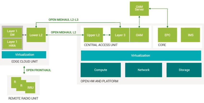
Abstract:
        The 5G RAN decomposition allows for a wide range of 5G services requirements to be met by allowing for RAN
        functionality to be split into centralised and distributed locations. There is a trade-off in terms of performance,
        complexity, flexibility, and transport demands that can allow an operator to decide what RAN decomposition(s) to
        deploy. This work provides an overview of the various RAN functional split options and their relative trade-offs.

        This work also provides an overview of the various industry activities that together form a toolbox enabling an
        operator to deploy the RAN functional split(s) of their choice.

        The functional split options can broadly be classified as either a high layer split (HLS) or a low layer split (LLS). The
        HLS is progressing as a work item within 3GPP. An overview of the 3GPP activities related to the HLS is provided
        here. For the LLS, the story is less mature, but still making significant progress. Many industry groups including,
        3GPP, eCPRI, xRAN, TIP, TTA, SCF, IEEE 1914, IEEE 802.1CM, are working on parts of the puzzle and
        specifications are already available or soon to be available from many of these groups. The final part of this
        document provides an overview of how these various aspects related to the LLS are developing.

NGMN Overview on 5G RAN functional decomposition                                                                            Page 2 (47)
Version 1.0, 24–Feb-2018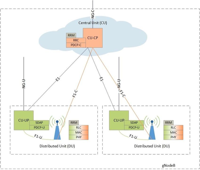
Contents
        1   Introduction ................................................................................................................................................................. 4
          1.1      Motivation ......................................................................................................................................................... 4
          1.2      Functional Split Options ................................................................................................................................... 4
        2 RAN architectures ...................................................................................................................................................... 6
          2.1      Migration Options ............................................................................................................................................. 6
          2.2      Functional Placement Options ........................................................................................................................ 8
          2.3      RAN Latency considerations ......................................................................................................................... 11
          2.4      Related industry activities .............................................................................................................................. 15
            2.4.1     CPRI ........................................................................................................................................................... 17
            2.4.2     OBSAI ........................................................................................................................................................ 19
            2.4.3     ETSI ORI .................................................................................................................................................... 20
            2.4.4     3GPP .......................................................................................................................................................... 21
            2.4.5     xRAN .......................................................................................................................................................... 24
            2.4.6     IEEE 1914 .................................................................................................................................................. 25
            2.4.7     TTA ............................................................................................................................................................. 26
            2.4.8     TIP .............................................................................................................................................................. 27
            2.4.9     Small Cell Forum ....................................................................................................................................... 29
            2.4.10        Open Air Interface ................................................................................................................................. 31
            2.4.11        802.1CM ................................................................................................................................................ 31
        3 High layer split (HLS)................................................................................................................................................ 34
          3.1      Introduction ..................................................................................................................................................... 34
          3.2      Architecture Option 2 ..................................................................................................................................... 34
          3.3      Separation of Control and User Planes ........................................................................................................ 35
          3.4      Deployment Considerations .......................................................................................................................... 36
            3.4.1     Scenario 1: Centralised CU-CP and CU-UP ........................................................................................... 36
            3.4.2     Scenario 2: Distributed CU-CP and Centralised CU-UP ........................................................................ 38
            3.4.3     Scenario 3: Centralised CU-CP and Distributed CU-UP ........................................................................ 40
          3.5      Latency ........................................................................................................................................................... 41
          3.6      Synchronisation .............................................................................................................................................. 41
          3.7      Encryption and Integrity Protection ............................................................................................................... 41
            3.7.1     Scenario 1 with Centralised CU-CP and CU-UP .................................................................................... 42
            3.7.2     Scenario 2 with Centralised CU-UP ......................................................................................................... 42
            3.7.3     Scenario 3 with Centralised CU-CP ......................................................................................................... 42
          3.8      Network Dimensioning................................................................................................................................... 43
          3.9      Summary ........................................................................................................................................................ 44
        4 Low layer split (LLS) ................................................................................................................................................. 45
        Abbreviations .................................................................................................................................................................... 46
        References........................................................................................................................................................................ 47

NGMN Overview on 5G RAN functional decomposition                                                                                                                                     Page 3 (47)
Version 1.0, 24–Feb-2018
1     INTRODUCTION

        1.1    Motivation
        The 5G system is being defined in phases to meet a wide range of use cases with diverse requirements, targeting
        a service-based, flexible, and efficient architecture, while pushing the performance limits. Fundamental aspects of
        the 5G flexible architecture are the CP/UP (control-plane/user-plane) split, and the RAN internal protocol-layer
        functional decomposition, the CU/DU (centralized-unit/distributed-unit) split. In here, we focus on the latter, though
        not independent of the other evolving architectural features, including CP/UP split. Furthermore, a RAN functional
        decomposition, in turn, implies a particular transport configuration towards the remote radio head.

        It is clear that RAN functional split has a number of implications and trade-offs, in terms of meeting service
        requirements (e.g. latency), complexity, centralized aggregation and capability integration, distributed flexibility,
        defined multi-vendor interface, and bandwidth, among others. In particular, the choice of functional split will
        determine the transport capacity requirement and associated latency specifications and performance. This will
        impact the network architecture as, for example, it can determine the placement of nodes and distance between
        them.

        There is obviously a need to evaluate the impact of the RAN functional decomposition, as applied to different use
        cases and deployment scenarios, as it impacts transport configuration and network slicing, and as it evolves to
        contribute to an end to end dynamic and reconfigurable 5G architecture. To align with the 3GPP standardization
        work, this work considers Option 2 and lower-layer options. However, this analysis allows us to go further and
        conduct a top-down review of options in terms of benefits, implications (performance, transport, scenarios), and
        trade-offs, for a service-based dynamic 5G architecture, and provide an overview of the industry activities that are
        working to define various components to form a 5G RAN.

        1.2    Functional Split Options
        Figure 1 shows the different possible split options. The top part was outlined initially in 3GPP Release 14 study on
        radio access architecture and interfaces [1] based on E-UTRA protocol stack.

                                                Figure 1: Functional split options

NGMN Overview on 5G RAN functional decomposition                                                                           Page 4 (47)
Version 1.0, 24–Feb-2018
As an example, Option 8 with only the RF functionality in the distributed unit has already been well known and
        continues to be deployed for densification. Other options have been the subject of further evaluation and definition,
        in terms of CU/DU split (e.g. Options 2 and 3) and simplified DUs and transport interface options (e.g. Options 6
        and 7). A current focus of 3GPP Rel 15 work item is Option 2 standardization, while lower-layer option(s), and
        CP/UP split for Option 2, are study items. The work on Option 2 benefits from leveraging the work already done for
        dual connectivity (3GPP Rel 12).

        A brief comparison of functional split options is provided in initial study [1] and subsequent work, while the
        standardization work and further studies are underway. This document further analyses some of the candidate
        options as well. However, some fundamental observations are obvious. Choice of different options from a fully
        distributed to a fully centralized RAN architecture can address different requirements, offering the associated
        benefits (such as edge computing, high throughput at high mobility or centralized processing and simplified
        distributed coverage), within constraints (such as cost or transport requirements). Ultimately, a flexible radio can
        address the service or operator requirements considering these trade-offs, potentially starting with a higher layer
        and a lower layer option.

NGMN Overview on 5G RAN functional decomposition                                                                          Page 5 (47)
Version 1.0, 24–Feb-2018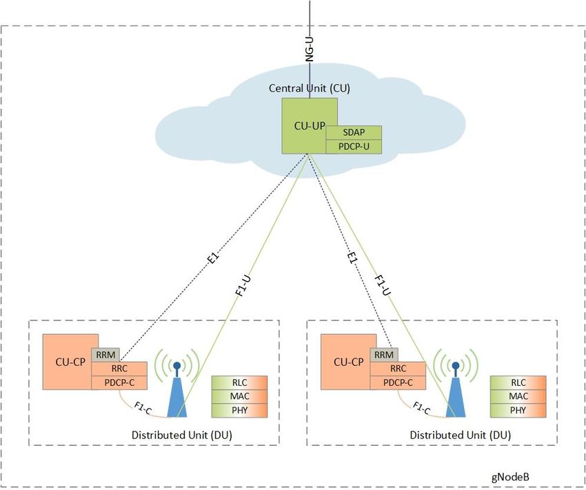
2 RAN ARCHITECTURES
2.1 Migration Options
A range of different 5G systems are being defined in 3GPP to offer support for multiple 5G migration scenarios.
Each system is characterised by the following factors and referred to by an “option” number (see Table 1):
Core network type: 4G EPC as defined in [2] with enhancements to support EN-DC vs. native 5G core
(5GC) as defined in [3]
NR or LTE/E-UTRA based master node which may be combined with a secondary node when the UE is
connected using dual-connectivity (e.g., EN-DC with EPC or MR-DC with 5GC)
In addition to inter RAT dual-connectivity using EN-DC and MR-DC the LTE and NR RANs may also
include support for intra RAT (i.e. NR-NR and LTE-LTE) Carrier Aggregation (CA) and Dual-Connectivity
(DC)
Table 1: 5G end-to-end system deployment options
Option Core network Master node Secondary node Generation
1 EPC eNB (LTE) - 4G
2 5GC gNB (NR) - 5G
3 EPC eNB (LTE) en-gNB (NR) 5G
4 5GC gNB (NR) ng-eNB (LTE) 5G
5 5GC ng-eNB (LTE) - 5G
7 5GC ng-eNB (LTE) gNB (NR) 5G
For the dual-connectivity options (3, 4 and 7) the RAN-core user plane interfaces may be terminated on either the
Master node (MN) or the Secondary Node (SN). Over the radio interface (Uu) traffic may be delivered using a
Master Cell Group (MCG) radio bearer or a Secondary Cell Group (SCG) radio bearer or Split radio bearer. See
[4], [5], and [6] for further details.
When deploying 5G networks, operators will need to consider both their first step solutions to be used when
opening 5G service and their subsequent evolution plan to add support for addition 5G use cases. Table 2 and
Figure 2 illustrates a range of example migration scenarios [7].
NGMN Overview on 5G RAN functional decomposition Page 6 (47)
Version 1.0, 24–Feb-2018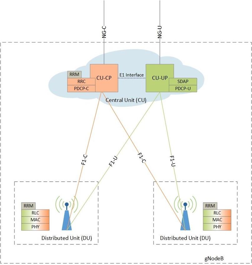
Table 2: Example 5G migration strategy options
Migration First migration step Subsequent migration step(s) Remarks
scenario
3 only Upgrade LTE RAN to support Expand coverage of option 3 Limited by lack of native
option 3 (EN-DC features) EN-DC access 5GC services
Add NR RAN to offer option 3 May include support for sub
EN-DC access 1 GHz NR carrier to improve
Upgrade EPC to support EN- wide area coverage
DC
3 > 5&7 Upgrade LTE RAN to support Upgrade LTE RAN to support Long term support for early
option 3 (EN-DC features) option 5/7 (e.g., introduce option 3 devices may be
Add NR RAN to offer option 3 5GC interfaces and MR-DC required
EN-DC access functionalities) May include support for sub
Upgrade EPC to support EN- Upgrade NR RAN to support 1 GHz NR carrier to improve
DC option 7 (e.g., introduce 5GC wide area coverage
interfaces and MR-DC
functionalities
Expand coverage of option 7
MR-DC access
Add 5GC core network
2 only Add NR RAN to offer option 2 Expand coverage of option 2 Initially rely on inter-system
NR only access NR only access handover to legacy 4G
Add 5GC core network when leaving NR coverage
May include support for sub
1 GHz NR carrier to improve
wide area coverage
May refarm legacy 2/3G and
4G spectrum to increase NR
coverage, capacity and
bitrates
3 > 2&4 Upgrade LTE RAN to support Upgrade LTE RAN to support May include support for sub
option 3 (EN-DC features) option 4 (e.g., Xn interface 1 GHz NR carrier to improve
Add NR RAN to offer option 3 and MR-DC and 5G QoS wide area coverage
EN-DC access functionalities Long term support for early
Upgrade EPC to support EN- Upgrade NR RAN to support option 3 devices may be
DC option 2/4 (e.g., 5GC required
interfaces, MR-DC and 5GS
QoS functionalities)
Expand coverage of option 4
MR-DC access
Add 5GC core network
2 > 2&4 Upgrade LTE RAN to support Upgrade LTE RAN to support May include support for sub
IRAT mobility (option 12) option 4 (e.g., Xn interface, 1 GHz NR carrier to improve
Add NR RAN to offer option 2 MR-DC and 5GS QoS wide area coverage
NR only access functionalities)
Add 5GC core network Upgrade NR RAN to support
option 2/4 (e.g., 5GC
interfaces, MR-DC and 5GS
QoS functionalities)
Expand coverage of option 4
MR-DC access
NGMN Overview on 5G RAN functional decomposition Page 7 (47)
Version 1.0, 24–Feb-2018
Figure 2: Example 5G migration strategy options
2.2 Functional Placement Options
Interfaces based on the RAN functional split options presented in Figure 1 may be classified into three classes:
Low Layer Split (LLS) between radio and central RAN functions:
o Being specified in various forums and standards bodies (i.e. IEEE 1914, CPRI forum and xRAN
Forum)
o Being studied in 3GPP for gNB, not expected to be specified in Rel 15
High Layer Split (HLS) between distributed and central RAN functions:
o Being specified in 3GPP as F1 for gNB [8]
o Being studied in 3GPP as V1 for eNB [9], not expected to be specified in Rel 15
CU-CP and CU-UP: control/user plane split within central RAN functions
o Being specified in 3GPP as E1 for gNB [8]
RAN-core interface:
o Specified in 3GPP as S1 ([2] and [4]) for EPC core
o Being specified in 3GPP as N2/N3 [3] or NG [8] for 5GC
The transport to connect functional units has a range of names within the industry, such as fronthaul, midhaul,
backhaul, x-haul, etc. The usage of these terms is not consistent among groups and individuals in the industry, so
can lead to confusion. For clarify, NGMN have chosen to adopt a more general naming system when discussing
the transport for the various interfaces in a disaggregated RAN. When talking about the transport to connect
functional units, we simply use the term “transport” and make it clear which interface is being used. For example,
“the transport for the F1 interface” or “the transport for the E1 interface”.
Furthermore, interfaces between RAN nodes are specified:
X2: Between central RAN functions in eNB and eNB or en-gNB ([4] and [9])
o In practice, split into X2-C and X2-U control plane and user plane interfaces
Xn: Between central RAN functions in ng-eNB and/or gNB ([6])
o In practice, split into Xn-C and Xn-U control plane and user plane interfaces
NGMN Overview on 5G RAN functional decomposition Page 8 (47)
Version 1.0, 24–Feb-2018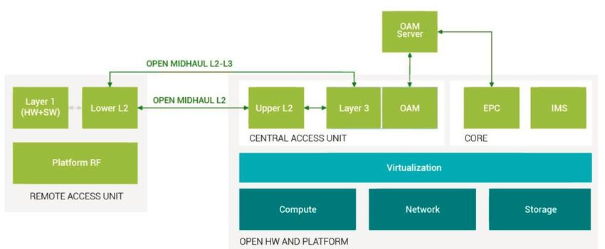
Due to overlapping use of identical terms the following terminology is adopted to describe LLS and HLS functional
splits:
RU: Radio unit. Contains all RAN functions placed below LLS interface
o CPRI Forum uses the terms “RE” and “eRE”
o xRAN Forum and TIP use the term “RRU”
o SCF uses the term “PNF”
o TTA uses the term “gNB-DU low”
DU: Distributed Unit. Contains all RAN functions placed between LLS and HLS interfaces
o 3GPP uses the same term “DU” to refer to all functions below HLS interface and hence refers to
both RU and DU
o CPRI Forum uses the terms “REC” and “eREC” to refer to all functions above LLS and hence
refers to both DU and CU
o xRAN forum uses the same term “DU”
o SCF uses the term “VNF” to refer to all functions above LLS
o TIP uses the term “vBBU” to refer to all functions above LLS for DU and CU, and “ECU” for DU
o TTA uses the term “gNB-DU high”
CU: Centralized unit. Contains all RAN functions above HLS interface and terminates inter-RAN interfaces
(X2, Xn)
o For the gNB, 3GPP splits this function into a single CU-CP control plane and one or more CU-UP
user plane functions
o xRAN Forum splits CU-CP into lower and upper parts and refers to CU-CP-H as xRANc with the
“southbound” B1 interface to remainder of RAN
o TIP uses the term “CAU” for all functions above the HLS for CU
Table 3: Terminology comparison
Function RU DU CU-UP CU-CP
Interface LLS HLS CP-UP
3GPP (gNB [8], [10]) gNB-DU CU-UP CU-CP
3GPP (eNB [9]) eNB-DU eNB-CU
3GPP (LLS [11]) lls-DU lls-CU
CPRI Forum (CPRI/eCPRI) RE/eRE REC/eREC
IEEE 1914 RU DU CU
xRAN RRU DU CU xRANc
SCF PNF VNF
TIP vRAN fronthaul RRU vBBU
TIP SI (Type 1) RAU CAU
TIP SI (Type 2) RRU ECU CAU
TTA gNB-DU-low gNB-DU-high gNB-CU
Combining these interfaces and taking into consideration the multi-connectivity options used to combine LTE and
NR access [5] the overall architecture for parallel LTE and NR RAN connected to both EPC and 5GC core
networks supporting and the terminology defined above, the full range of deployment options described in section
2.1 is shown in Figure 3.
NGMN Overview on 5G RAN functional decomposition Page 9 (47)
Version 1.0, 24–Feb-2018Figure 3: Overall RAN architecture
The individual functional entities RU, DU, CU-UP and CU-CP entities may be place at different physical locations
according to operator requirements, physical site constraints and transport network topology, latency and capacity
limitations. An additional constraint is the cardinality restrictions driven by the RAN-Core interface design
assumption that a given RAN has a single control plane termination point that implies that a given RAN may only
have a single CU-CP entity.
Figure 4 presents a selection of example functional placement options based on the assumption that the RAN may
have functionality placed at:
Cell site
Aggregation site (intermediate site, traditionally used for transport aggregation and may have been used to
host legacy BBU hoteling)
Edge site (most central site in RAN)
Table 4 provides additional information on each of the example functional placement options and highlights which
interfaces would be used linking physically separate sites.
NGMN Overview on 5G RAN functional decomposition Page 10 (47)
Version 1.0, 24–Feb-2018Figure 4: Example functional placement scenarios
Table 4: Summary of example functional placement scenarios
Placement option Cell site Aggregation site Edge site Inter-site interfaces
Central RAN (LLS) RU DU, CU LLS
Split RAN (HLS) RU, DU CU F1c, F1u
Dual split RAN RU DU, [CU-UP] CU LLS then F1c, F1u,
[E1]
Remote CU-UP RU, DU, [CU-UP] CU-CP, CU-UP F1c, F1u, [E1]
Central CU-UP RU, DU, CU-CP, CU-UP F1u, E1
[CU-UP]
Cell site RAN RU, DU, CU S1 and/or NG
Note: optional functions and interfaces required to local CU-UP shown as [CU-UP], [E1], etc.
2.3 RAN Latency considerations
In order to satisfy the latency requirements for 5G services, an operator must ensure the physical locations of any
user plane functions (UPF) or multi-access edge computing (MEC) functions are close enough to the user. This
can put a strict limit on how much functions can be centralised. The benefits of distributed UPFs are realised when
content (or service in case of hosted web-apps or compute) is also local. When traffic comes from the Internet then
the latency benefit is lost. At the same time there is an incentive to centralise functionality as much as possible to
maximise benefits such as pooling gains. The ideal locations for functions to be placed in the network is therefore a
compromise that each operator must evaluate and then ensure these physical locations have the necessary
transport and compute capability.
Figure 5 shows a simplified example of a 5G RAN topology supporting a range of macro and small cells1. Any
traffic routed from these sites towards a central entity will pass through a series of aggregation sites. Table 5
provides some indicative values of the relative number of sites. For example, for every 1000 tier 1 sites, there are
only 100 tier 2 sites. If a UPF is located in a tier 1 site, then 1000 tier one sites will all have to run their own version
of that UPF. If the UPF is moved into a tier 2 site, then only 100 versions of that UPF are required. This level of
1 For the following discussion macro sites are considered, simply because the diagram can be modified more
clearly to provide examples. Disaggregation of small cells follows the same principles, although there may be
different decisions made for small cells and macro cells.
NGMN Overview on 5G RAN functional decomposition Page 11 (47)
Version 1.0, 24–Feb-2018pooling benefit can save an operator considerable cost in running the UPF. However, the UPF can only be
centralised so far as the latency budget is still met, plus other factors such as transport capability. Table 5 also
provides some indicative values for transport latency. The one way latency from the cell site to a tier 1, tier 2 and
tier 3 aggregation site are 0.6ms, 1.2ms and 4.2ms respectively2. Table 5 also provides some indicative values for
the 5G latency if a UPF is located at these various aggregation sites. This considers the RAN latency for eMBB and
URLLC, plus the round-trip times of the transport network. As a result we can see that it would be difficult to locate
a 5G UPF in a tier 3 site as the service latency is probably too high. E.g. 16.4ms for eMBB. However, for a 5G
service with approximately 10ms latency requirement an operator will have to look very carefully at tier 1 and tier 2
locations. While tier 1 has slightly better latency performance, tier 2 can provide significant cost benefits.
Figure 5: Example 5G RAN with multi-tier aggregation
Table 5: Example maximum latency figures for 5G RAN aggregation sites3
For a disaggregated RAN, the location of the DU and CU can also follow similar considerations as the UPFs. The
obvious restriction is that the DU and CU would not typically be more centralised than the UPF, otherwise
unwanted tromboning effects will occur resulting in further latency increases, as well as possible transport
2 Latency figures based on 95th-percentile of transmission delay (i.e. 95% of cell sites are within this) +
overhead for IP
3 Assumptions:
Maximum Latency figures based on 95th-percentile of transmission delay (i.e. 95% of cell sites are
within this) + overhead for IP
5G RTT assumes 8ms overhead for 5G New Radio & Next-Gen Core (eMBB case) – 1ms for
URLLC (as per 3GPP release 15)
NGMN Overview on 5G RAN functional decomposition Page 12 (47)
Version 1.0, 24–Feb-2018congestion.4 Based on the values in Table 5, Figure 6, Figure 7 and Figure 8 show the most likely locations for DU
and CU placement to support different 5G latency requirements.
For ultra-low latency 5G services the CU and DU, as well as any UPF or MEC functions, must all be located at or
near the cell site, as shown in Figure 6. The reason being that the latency requirement is so stringent that any
significant transport latency is not acceptable. In practise this does mean that ultra-low latency capability is unlikely
to be provided network-wide. The capability can be added on an ad hoc basis, focussing only on those locations
where such extreme latency requirements exist.
Figure 6: Example CU, DU, UPF, MEC placement for ultra-low latency (approx max. 1ms RTT)
Figure 7 shows the likely placement of DU and CU for low latency 5G services. This covers services like eMBB
where the typical user plane round trip time (RTT) of approximately 10ms is targeted. It is likely that the DU would
remain at the cell site, however tier 1 is a possibility. However, it seems that the CU can be located at a tier 2 site,
the same as the UPF. This would achieve the best compromise between centralisation gains while still being able
to provide a service with approximately 10ms RTT.
By comparing the physical locations of functions for ultra-low latency and low latency services it can be seen there
is a middle ground, which might be called very-low latency. This is shown in Figure 8. While these DU and CU
placements may often fail to satisfy any ultra-low latency services, and would probably fail to be a cost effective
way to provide low latency services, there may be a range of 5G services which require a performance latency
such as this. This architecture may also be used to offer ultra-low latency services in local areas (stadium,
downtown dense urban areas, campus sites, etc.) with low latency (What these indicative values and placements highlight is that an operator will have to consider the 5G services that
they want to provide while also considering the details of their transport network, when they begin to plan where
they can place the DU and CU.
Figure 7: Example CU, DU, UPF placement for low latency (approx max. 10ms RTT)
Figure 8: Example CU, DU, UPF, MEC placement for very-low latency (approx max. 5ms RTT)
NGMN Overview on 5G RAN functional decomposition Page 14 (47)
Version 1.0, 24–Feb-20182.4 Related industry activities
There are a number of industry groups that play a role in defining or implementing RAN functional splits. These are
summarised below in Table 6. This section then discusses the related activities in those groups in more detail. As
mentioned earlier, NGMN refers to transport for interfaces in the disaggregated RAN by using the term “transport”
and specifying which interface is being used (e.g. transport for F1 interface). In this section, however, when
discussing each group’s activities, we adopt their terminology.
Table 6 not only provides an overview of the related activities of each industry group, it also comments on whether
the interfaces being developed can be considered as open interfaces. For an interface to be considered as being
“open” it should meet the following criteria:
Specified to a level to enable multi-vendor interoperability
Cover the following data planes
o User plane
o Control plane (slow and fast)
o Management plane
o Synchronization plane
Table 6: Summary of industry activities
Industry Summary of Activities Status/Maturity (as of Open/plug-and-play
organisation February 2018)
CPRI De facto Industry standard for BB-RRU Latest version CPRI V7.0 2015 Openly available, does
interface since 2004. [12]. not cover M plane.
eCPRI enabling use of switched packet eCPRI v1.0 published Aug 2017,
networks and Ethernet/IP. 10 times V1.1 in Jan 2018 [13].
reduction in bandwidth demand compared
to CPRI.
OBSAI Architecture and interfaces for Cellular Mature since 2004. Used since Openly available, scope
Base station. 2004 in high volumes. like in CPRI.
ETSI ORI Specification for interoperable BB-RF Closed, very limited market Open
interface based on CPRI adoption.
3GPP High Layer Split (HLS) and Low Layer HLS interface (F1) between DU F1 and E1 are open
split (LLS) interfaces considered along and CU approved (38.47x series) interfaces specified by
with CP-CU split. E1 interface between CU-UP 3GPP
Low Layer Split (LLS) is still a study item. and CU-CP study report [10]
approved and WI (due June
2018) started
LLS interface Study Item (SI)
report [11] approved, possible
continuation of the SI on hold
xRAN Evaluated benefit, cost and technical First draft of specification is It will be an open
feasibility of different fronthaul split options targeted to be made available by standard specification
to develop an open, efficient & end of Q1 2018. and xRAN is
interoperable specification for DU – RU The first draft will include user- responsible for version
communication. plane/control-plane interface control and updates.
Selecting the fronthaul split option for the functions and the architecture The specification
xRAN fronthaul specification addressing definition of the management- enables interoperability
4-8T and Massive MIMO configurations plane. between DU-RU
for LTE & NR vendors. The
xRAN fronthaul whitepaper capturing specification aims to
Stage 1 objectives published [14] achieve a high degree
Development of detailed fronthaul of interoperability, but
specification ongoing some aspects of
configuration
management are likely
to be product specific
IEEE 1914 1914.1: Use cases, architecture and 1914.1: near-stable draft. It is Mechanism defined in
NGMN Overview on 5G RAN functional decomposition Page 15 (47)
Version 1.0, 24–Feb-2018requirements on next generation fronthaul expected to have it publish by 1914.3 is targeted at
interface (NGFI) networks; mid- 2018. realizing open interface;
1914.3: a) Encapsulation & mapping of 1914.3: technically mature
radio signal into Ethernet packets; b) Also enough, now at the sponsor
defines objects (as well as their ballot stage. The specification is
parameters and formats) to be expected to be published in the
transported over the RoE link for 3GPP 1st half year of 2018. Meantime,
functional split options 8, 7.1, and 7.2. To 1914.3 is discussing to extend
support open interface; the support of open interface to
other split options.
TTA Has developed open interface between Specification published on Dec. Fx is an open interface
gNB-CU and gNB-DU (intra-PHY split) 2017 ([15], open for revision in for lower layer split
the future) – Currently only
available in Korean. English
translation expected at a later
date.
TIP The Solutions Integration project has Solutions Integration project has High layer spec will be
developed open interfaces for two almost completed its activities. open.
architectures for disaggregated LTE base Open specifications are likely to Low layer spec
stations, both of which use high layer split be published soon expected to be open
[16]. The vRAN fronthaul project is
The vRAN fronthaul project is focussed just starting its lab development
on developing solutions which adopt a low phase, based on a high-level
layer split, that will function over non-ideal specification.
fronthaul [17]
Small Cell Has developed specification for
Specification published, although Open spec published
Forum MAC/PHY (option 6) functional split of occasionally readdressed, for as nFAPI
LTE [18] LTE updates
OAI Open source software implementation of
LTE.
Includes split options 8 and 7-1.
Integrating SCF nFAPI
Developing NR solution with F1 interface
IEEE 802.1CM IEEE P802.1CM is a Time-Sensitive The Standard specifications is This is a Profile
/ TSN Networking profile standard for Fronthaul stable and under its first IEEE SA Standard which
(and Midhaul) transport networks. Sponsor Ballot (i.e. no technical improves
It specifies bridged transport networks change). interoperability and can
over IEEE Std 802.3 Ethernet for the The Standard P802.1CM is be applied to allow time
transport of fronthaul traffic, including user expected to be finalised and synchronisation for
data, and control & management (C&M) published before the end of 2018 most types of Fronthaul
data. and possibly earlier. and functional splits
It utilises a range of enhanced over bridged Ethernet
functionalities and options from IEEE 802 networks.
Ethernet standards including VLAN
Bridge, Interspersing express traffic,
Frame preemption specification, and Time
Synchronisation.
The Standard P802.1 supports low
functional splits as in CPRI and eCPRI
specifications but other functional splits
are possible in the future with amendment
to the standard. Higher functional split are
relatively easier to cover since they are
characterised with less stringent
requirements.
NGMN Overview on 5G RAN functional decomposition Page 16 (47)
Version 1.0, 24–Feb-20182.4.1 CPRI
The Common Public Radio Interface (CPRI) is an industry cooperation aimed at defining publicly available
specifications for the key internal interface of radio base stations. The parties cooperating to define the specification
are Ericsson AB, Huawei Technologies Co. Ltd, NEC Corporation and Nokia.
The initial objective of the CPRI forum, created in 2004, was to produce a specification for digitized and serial
internal base station interface between the 'Radio Equipment Control' (REC) and the 'Radio Equipment' (RE).
The CPRI Specification version 7.0 was published in October 2015 [12], and adds 24G line-rate to the previously
released 10G line rate. The CPRI specification covers split option 8. Single and multiple hops with chain, tree and
ring topologies are supported. The specification supports GSM, WiMAX, UMTS, LTE and LTE-Advanced.
Three different information flows (User Plane data, Control and Management Plane data, and Synchronization
Plane data) are multiplexed over the interface. The specification covers layers 1 and 2. 3a. The physical layer
(layer 1) supports electrical interface as well as optical interfaces.
In August 2017, the CPRI forum released the first version of the eCPRI specification, with an update in January
2018 [13].
Compared to the CPRI, eCPRI makes it possible to decrease the data rate demands between eREC and eRE via
a flexible functional decomposition while limiting the complexity of the eRE.
The scope of the eCPRI specification is to enable efficient and flexible radio data transmission via a packet based
fronthaul transport network like IP or Ethernet. eCPRI defines a protocol layer which provides various - mainly user
plane data specific - services to the upper layers of the protocol stack.
Figure 9: eCPRI system
eCPRI Protocol Overview
The eCPRI interface includes the following information flows:
1. User Plane:
o User Data:
User information (to be transmitted from/to the base station to/from the user equipment) with
format depending on the underlying functional decomposition between the eREC and the eRE.
o Real-Time Control data:
Time-critical control and management information directly related to the User Data.
o Other eCPRI services:
eCPRI services such as User Plane support, remote reset, etc.
2. C&M Plane:
NGMN Overview on 5G RAN functional decomposition Page 17 (47)
Version 1.0, 24–Feb-2018o Control and management information exchanged between the control and management
entities within the eREC and the eRE. This information flow is conveyed to the higher protocol
layers and is not considered time critical.
3. Synchronization Plane:
o Synchronization data used for frame and time alignment.
eCPRI defines a protocol for the transfer of user plane information between eREC and eRE via a packet based
fronthaul transport network. For C&M and synchronization information flows, existing protocols and standards are
referenced as proposals. The interface supports Ethernet-switched or IP-routed fronthaul networks.
Functional decomposition options
Figure 1 in this document shows the protocol stack layers and possible split points for a 3GPP 4G (LTE) or 5G
(NR) radio base station. Figure 10 below shows a more detailed view of the PHY layer. Two inter-layer functional
splits D and E (Options 6 and 8 in 3GPP) are depicted in the figure. One additional set of intra-PHY splits named
“{ID, IID, and IU}” is also shown. The CPRI specification uses split E. The eCPRI defines two splits for downlink traffic
( ID and IID ) and one for uplink ( IU ). Three sub options of the 3GPP split option 7 are also shown for reference.
Figure 10: Functional decomposition options inside PHY layer
The advantages of the intra-PHY-split are: features such as Carrier Aggregation, Network MIMO, Downlink CoMP,
and Uplink L1 CoMP Joint Processing can be efficiently supported. Some of these features might of course be
supported by other splits as well.
NGMN Overview on 5G RAN functional decomposition Page 18 (47)
Version 1.0, 24–Feb-2018Some disadvantages of the intra-PHY-split are: A fronthaul network with “higher” capacity and “lower” latency is
required compared to higher layer splits.
As a summary, eCPRI offers the following benefits compared to original CPRI specification:
1. ~10 fold reduction of required bandwidth
2. Required bandwidth can scale flexibly according to the user plane traffic
3. Functional split inside PHY layer enables support of sophisticated coordination algorithms
4. Split in PHY keeps most of the functionality in baseband enabling new feature introduction without
changes in the radio equipment
5. Enables utilization of Ethernet and IP, thus guaranteeing future evolution
In addition to the actual Specification CPRI Cooperation has also published the document “Requirements for the
eCPRI Transport Network” covering the main requirements of eCPRI traffic to the packet networks [19].
2.4.2 OBSAI
The Open Base Station Architecture Initiative (OBSAI) is an industry group containing base station, module, and
component manufacturers. It was established in 2002 with the aim to reduce development costs and encourage
greater innovation through open base station architectures and open interfaces. OAM is defined to enable
integration of multiple vendors into a base station.
Figure 11 shows the OBSAI reference architecture. Of particular interest, for this whitepaper, is the reference point
3 (RP3) interface which defines the communication between a baseband block and RF block, then variation RP-01
which defines the communication between a baseband block and a remote RF block. This split would be option 8
split in 3GPP terminology. Other key modules in the architecture are the transport block and the control and clock
block.
Figure 11: OBSAI architecture [20]
NGMN Overview on 5G RAN functional decomposition Page 19 (47)
Version 1.0, 24–Feb-20182.4.3 ETSI ORI
The NGMN project on open BBU-RRH interface (P-OBRI) was initiated to develop a recommendation for an open
interface between BBU and RRH. Existing BBU-RRH interfaces, based on industry standards like CPRI or OBSAI
do not provide a plug and play interoperability. To achieve the fully interoperable goal, options were removed and
functions were added to the CPRI specification. OBRI was initially built on version 4.1 of the CPRI specification,
and added a C&M layer, not included in the CPRI specification, but required for interoperability.
The preparation phase of this activity started as a task force in September 2008. The NGMN project started in May
2009 and drafted the OBRI Implementation Requirements (IR) which focuses on 3GPP radio access technologies,
UTRA-FDD, E-UTRA-FDD and E-UTRA-TDD as well as multiplexing between UTRA-FDD and E-UTRA-FDD.
The OBRI project then submitted its draft recommendation to ETSI ORI as a baseline document for further
development. The ETSI ORI specification work was supported by leading mobile network operators and
telecommunication equipment vendors. In the continuation of the work conducted in NGMN, the ORI interface was
built on top of the interface already defined by the CPRI group. The ETSI group was closed in July 2016. ORI ISG
deliverables is maintained by the ETSI Technical Body RRS accessible via the ETSI Portal.
The first release of the ORI interface, published in 2012, provided a digitized radio base station interface enabling
single-hop topologies. Different information flows (User Plane data, Control and Management Plane data, and
Synchronization Plane data) were multiplexed over the interface. ORI covers OSI protocol Layer 1, Layer 2 up to
Layer 7 and is based on CPRI version 4.1. ORI Release 1 provided support for UMTS, LTE and LTE-Advanced
technologies.
ORI Release 2 added support for multi-hop topologies and RRU chaining, as well as 9.83 Gbit/s line bit rate, and is
based upon CPRI version 4.2.
ORI Release 3 extended support to GSM technology and was based on CPRI version 5.0.
ORI Release 4, published in October 2014, was based on CPRI version 6.0. Release 4 adds IQ data compression
for LTE and supports a line bit rate up to 10.14 Gbit/s. This is particularly useful in C-RAN type network topologies.
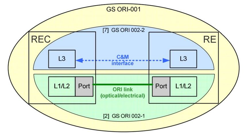
Figure 12 shows the document structure of the ORI specification available on the ETSI portal. The Low Layers
specification (reference [2] in the diagram) covers a single ORI link. The C&M specification (reference [7] in the
diagram) covers C&M communication between one REC and one RE. The present requirements specification
covers a system configuration of multiple ORI links between one REC and one or multiple REs and optionally
additional subsequent ORI links between those REs and other REs.
NGMN Overview on 5G RAN functional decomposition Page 20 (47)
Version 1.0, 24–Feb-2018Figure 12: Document structure of the ORI specifications [21]
A number of interface tests have been performed, confirming the interoperability objectives. Despite being a well-
defined open standard, the level of adoption in the industry to date remains very limited.
2.4.4 3GPP
3GPP RAN3 working group has selected Option 2 High Layer Functional Split Architecture for the evolved 5G RAN
Architecture. In the evolved architecture, the protocol and functional stack of a legacy eNodeB has been split,
whereby the RRC and PDCP functions are centralised in a Centralised Unit (CU) and RLC, MAC and PHY
functions are left in the remote Distributed Unit (DU). This High layer split configuration allows greater centralisation
of RAN functions whilst maintains tight synchronisations and integration of RLC-MAC-PHY functions.
The evolved architecture has gone through further evolution where the Control and User Planes have been split.
By splitting the Control and User Planes the Signalling and Data functional block within the CU have also been split
up: this functional split allows for greater flexibility of the RAN network design. Furthermore the split functional
blocks allows for independent scaling of the Signalling and Data Delivery equipment with increasing traffic load in
the RAN network.
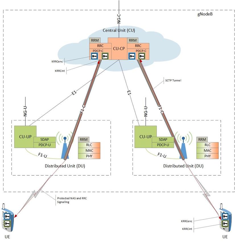
The split Control and User Planes allows for three distinct deployment scenarios:
1. Scenario 1: Centralised CU-CP and CU-UP (Figure 13)
2. Scenario 2: Distributed CU-CP and Centralised CU-UP (Figure 14)
3. Scenario 3: Centralised CU-CP and Distributed CU-UP (Figure 15)
NGMN Overview on 5G RAN functional decomposition Page 21 (47)
Version 1.0, 24–Feb-2018Figure 13: Scenario 1, Centralised Control Signalling and User Plane Functions NGMN Overview on 5G RAN functional decomposition Page 22 (47) Version 1.0, 24–Feb-2018
Figure 14: Scenario 2, Centralised User Plane function, CU-CP is in the DU

                    Figure 15: Scenario 3, Centralised Control Plane function, CU-UP is in the DU

NGMN Overview on 5G RAN functional decomposition                                                    Page 23 (47)
Version 1.0, 24–Feb-2018
Where CU-CP refers to the Control signalling functional block within the CU and CU-UP refers to the User Plane
functional Block within the CU.
Each deployment scenario provides a number of advantages and allows the User Plane function or the Control
Plane functions to be co-located with the DU.
Due to the significant progress in 3GPP for the HLS, chapter 3 provides a much more detailed overview of these
activities.
2.4.5 xRAN
xRAN is a non-profit industry consortium that was formed by carriers to develop, standardize and promote an open
alternative to the traditionally closed, hardware-based RAN architecture. The xRAN architecture is complementary
to 3GPP and other standards bodies and hopes to provide a blueprint that these standards bodies can use for
architecting the future RAN as the industry moves towards 5G.
Standardization and specification of the BBU-RRU interface is currently under investigation in many organizations
such as 3GPP, IEEE 1914 & eCPRI. However, xRAN intends to meet the need of operators in defining a
specification that can address future deployment scenarios and that can be said to be truly vendor-agnostic and
interoperable. The xRAN Fronthaul working group is focused on producing an “Open” specification for next
generation fronthaul between the remote radio unit (RRU) and the virtualized baseband unit (BBU), to address
future use cases and deployment scenarios [14]. This work will also include the specification of the operation and
management (OAM) interface to simplify interoperability between different BBU and RRU suppliers.
xRAN has identified the following operator requirements for the open interface are:
A BBU – RRU interface that helps achieve interoperability, more specifically in the control and
management plane functions
Control and management functions of the interface should adopt a data model approach to simplify
integration of diverse radio implementations as well as multiple intra-PHY split options
The design should minimize optionality in traffic and management plane to meet key requirements and
simplify development and interoperability
The interface should cater to multiple deployment use cases as described below:
a) Support use of advanced receivers for high performance 4G & 5G eNB and gNB deployments
b) Support Cloud RAN deployments and associated features (CoMP, CA etc.)
c) Scale efficiently to address large antenna configurations (Up to 64T-64R)
d) Support specialized functions in radios to cater to listen-before-talk operations (e.g LAA)
e) Support live migration of BBUs
The interface should reduce bandwidth utilization relative to CPRI and scale as a function of user
throughput
The interface should utilize standardized Ethernet based technologies for transport & enable switching
using standardized switching infrastructure
The interface should address RRU flow aggregation and improve resiliency by supporting switching traffic
between BBUs
Standards based BBU – RRU synchronization solutions should be addressed
To meet service needs of the diversified user devices (smartphones, IoT devices, autonomous car, etc.),
the fronthaul split should support Network Slicing requirements
NGMN Overview on 5G RAN functional decomposition Page 24 (47)
Version 1.0, 24–Feb-20182.4.6 IEEE 1914
The IEEE 1914 next generation fronthaul interface (NGFI) working group (WG) was officially founded in February
2016. The WG is positioned as a platform to study NGFI-related key technologies, develop relevant standards
development, and ultimately accelerate a mature NGFI ecosystem. Currently there are two projects under the 1914
WG. The 1914.1 project is to describe the NGFI use case and develop the NGFI transport architecture as well as
the requirements. The 1914.3 project is specifying the encapsulation format of radio signal into Ethernet packet.
The 1914.1 project has finished the study on use cases, achieved consensus on the transport architecture and
begun the standards development on requirements. The requirements will be made from transport network/nodes
perspective and will cover the area of performance, O&M, slicing, reliability, flexibility and so on. In addition, the
NGFI node reference model and a class of service are being discussed/defined. The 1914.1 plans to have its draft
specification ready by June 2018.
Another project, IEEE 1914.3 is an international standard that defines how radio information (data and control) is
mapped into Ethernet frames with standardized Radio-over-Ethernet (RoE) headers. It supports the encapsulation
of time-domain IQ (e.g. traditional CPRI) and frequency domain IQ including functional split options 7-1 and 7-2
defined in 3GPP.
One of the key features of 1914.3 specification is that it is open and allows all compliant equipment to interoperate.
For example, for split option 7-1, the WG has defined extensive control and management messages which the WG
thinks could support open (option 7-1) split to large extent.
In 1914.3 several mapping methods are defined:
Structure agnostic
o An entire stream of radio information, of any format, is mapped into Ethernet at the RoE mapper
and restored to its original form at the RoE demapper. This mapping method has a tunneling
mode, where the entire stream is mapped, and a line-coding aware mode, where 8B/10B or
64B/66B line-encoding and scrambling is removed before the information is mapped and is
reinserted after the information is demapped.
o CPRI streams can be carried over Ethernet using the structure agnostic mapping method.
Structure aware
o The structure of the protocol that carries radio information is known to the structure aware
mapper. I/Q data and control messages extracted from the protocol are mapped into unique
Ethernet frames.
o Specific methods have been defined for the structure aware mapping of CPRI.
Native RoE
o Time-domain or frequency-domain I/Q information (the corresponding function splits include
option 8, 7-1 and option 7-2 defined in 3GPP) is mapped into Ethernet by the Native RoE
mappers. Control information is transported via TLVs (type length value encoding) in control
messages.
This standard also defines mechanisms that enable the demapped data to be presented to the radio equipment at
the desired time.
Figure 16 may give readers a basic idea of RoE packet format.
NGMN Overview on 5G RAN functional decomposition Page 25 (47)
Version 1.0, 24–Feb-2018Figure 16: RoE packet format (http://sites.ieee.org/sagroups-1914/)
As a general encapsulation & mapping method, the RoE specification could apply to any functional split option for
both the control plane and the data plane. Currently, to support an open interface, the RoE specification defines
specific objects (as well as their parameters and formats) to be transported over the RoE link for 3GPP functional
split options 8, 7.1, and 7.2. Extension to other functional split options and other control plane objects are expected
in the next-stage work. With the RoE specification, it is expected that an open interface can be realized to enable
multi-vendor interoperability.
2.4.7 TTA
The Telecommunication Technology Association of Korea (TTA), establish, revise, and distribute Korean ICT
standards in communication networks, ICT convergence, security, software, broadcasting, radio/mobile
communications. They also test and certify ICT products and services in accordance with the domestic and
international standards, and develop testing standards. They also provide support to enhance the competitiveness
of small and medium-sized enterprises.
Relevant to this discussion is working group (SPG31), whose role covers 5G radio standardisation. For 5G they
transpose 3GPP technical specifications into TTA standards and also develop and maintain 5G RAT standards.
TTA also have international collaborations with related industry groups such as 3GPP and NGMN.
Figure 17 shows TTA’s 5G RAN architecture with a high layer split (option 2 in 3GPP terminology) and a lower
layer split (option 7 in 3GPP terminology). In December 2017 the 5G open interface was published [15]. This
provides the specification for the Fx interface between the gNB-CU and gNB-DU. This specification can apply to all
variants of the option 7 split. The specification covers user plane, control & management plane, and
synchronisation.
This specification has tried to stay in alignment with other industry activities. The architecture itself is in alignment
with that discussed within 3GPP. The packet format is based on IEEE 1914.3 RoE, and includes mapping for the
CPRI specification.
NGMN Overview on 5G RAN functional decomposition Page 26 (47)
Version 1.0, 24–Feb-2018Figure 17: TTA architecture
2.4.8 TIP
The Telcom Infra Project (TIP) was founded in February 2016 and is an engineering-focused initiative driven by
operators, suppliers, developers, integrators, and start-ups to disaggregate the traditional network deployment
approach [17].
2.4.8.1 Solutions Integration
This project aims to develop an “Unbundled RAN” architecture [16]. This means splitting the base station into
functional blocks and defining open specifications for those functional blocks to communicate, thus enabling multi-
vendor interoperability. The activity has focussed initially on LTE solutions and two RAN architectures, as shown
below. The common theme for both of these architectures are the OAM components and the PDCP-RLC split
(option 2 split, in 3GPP terminology) in the LTE stack. The main variation among the two architectures is that type 1
architecture includes a single unit, the remote access unit, to contain the RLC/MAC/PHY/RF, while the type 2
architecture has two units: the edge cloud unit which contains RLC/MAC/PHY, and the remote radio unit containing
the RF (this is an option 8 split in 3GPP terminology). The connection between the edge cloud unit and remote
radio unit will be based on CPRI or ETSI ORI. The open APIs are due to be published shortly.
NGMN Overview on 5G RAN functional decomposition Page 27 (47)
Version 1.0, 24–Feb-2018You can also read