NOTESFROMTHEVACUUMSHACK NO.17APRIL2021 - THE BELL JAR
←
→
Page content transcription
If your browser does not render page correctly, please read the page content below
Notes from the Vacuum Shack No. 17 April 2021
In this issue:
Mark Atherton on coupling RF to a plasma and transfer characteristics for his triode
Chuck Sherwood on his evolving electron source
Updates on atmospheric pressure plasma power supplies and ongoing projects
Articles of possible interest in Vacuum Technology & Coating
RF Excited Plasma
Mark Atherton, New Zealand markaren1@xtra.co.nz
Background
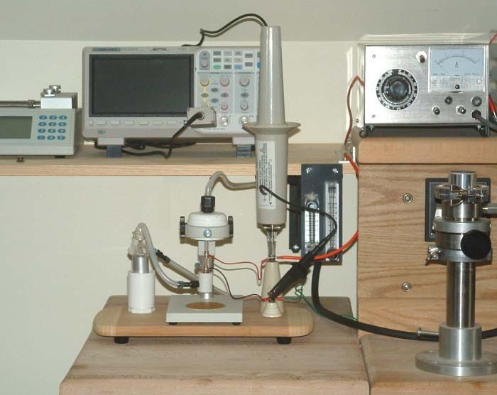
This document describes an experiment to investigate plasma-initiation using minimal RF power
(and radiated signal) using a tuned network, with a balanced output. Test loads include an Atlas
12”, 8 watt fluorescent tube, and a Russian IN-13 (ИН-13) neon tube. The RF source was a Tait
T-2000 set to an unused low-band VHF frequency; Channel 1 was set to low power (3 watts) and
Channel 2 to high power (25 watts). Reflected RF power was monitored using a Bird 43 meter
with 5 watt slug appropriate for the excitation frequency.The set up is shown in the picture below.
The figures on the next page show the initial schematic for the coupler and a picture of the
coupling network.
The main inductor was 6 turns of 1.6 mm diameter copper wire wound on a 22 mm diameter
former. The input loop was a single turn of 7/0.2 stranded wire. The butterfly capacitor (C1) was
used in an attempt to balance the output voltage by swamping any out-of-balance parasitic
capacitances in the feed wiring to the load.
the Bell Jar, No. 17, April 2021
1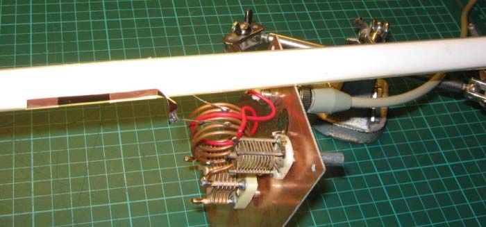
Early Experiments

With the 8 watt tube inserted into the coil, a region in the centre of the tube could easily be
ignited using 3 watts of power after adjusting the tuning and loading capacitors. Reflected power
was in the order of 0.5 watts, which equates to a VSWR in the order of 2.4 : 1. Rather
unexpectedly, just sitting the 8 watt tube in close proximity of the butterfly capacitor ignited
almost all of the tube. Waving the tube around the butterfly capacitor resulted in a dimming
around the centre of the capacitor; this might be expected since that would not be a voltage-field
maximum.

The experiment was repeated using the ИН-13, but without success. It was possible to ignite this
device using a momentary burst of high power, but this only worked partially. It was noted that
the tube was rather hot at one end after this, which may be explained by RF heating of the

                                   the Bell Jar, No. 17, April 2021
                                                  2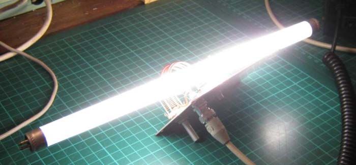
internal metal structure (which is surrounded by neon).

Electrostatic Ring-Feeds

Six strips of copper foil were wrapped around the 8 watt tube, spaced 15 mm apart. Alternate
rings were strapped together and attached to J2 and J3 of the butterfly capacitor. The unit was
energised and tuned for minimum reflected power and the tube struck as expected. It was noted
that both capacitors were fully un-meshed and reflected power was much greater than previous
experiments. It seems reasonable that the new capacitive loading of the tube has taken the tank
circuit outside of its adjustable range.

Having removed one turn off of L2, the tuning range was very much broader using all six
coupling rings. Two rings were taken out of circuit and the tube would strike with the C1 meshed
75%, and C2 meshed 100%. Two more rings were taken out of circuit, and behaviour stayed very
similar to when 4 rings were present.

High Impedance Feed Tests

During this series of tests, I had an overwhelming feeling that the ring-coupling method (even
when only using just two rings) was much too tightly coupled. The system could reliably ignite
the tube, but not as well as had been found (accidentally) earlier. The stability, low reflected
power, and sheer light output from the tube just sitting on top of the butterfly capacitor always
seemed the best option. This may imply a very lightly coupled load, being driven with much
more available voltage.

Output Impedance Change

From the observations so far, it appears that there is a
significant impedance mismatch between source and load.
Part of the issue probably relates to the difference in load
impedance between un-ionised and ionised states of the
tube. The feed point from the output inductor was moved in
by one turn from each turn, so the topology was now 1.5
turns, 2 turns, 1.5 turns. This is shown in the schematic to
the right.

This is the first time that it was possible to adjust tuning for
an almost perfect match, with only a hundred milliwatts or
so of reflected power. It was surprising that such a relatively low drive voltage was still able to
ionise the tube. Once this optimum match had been reached, it was not possible to re-ionise the
tube without also retuning the network.

In-line Coupling Feed

A further test was made by applying two strips of copper-foil, each 5mm wide and 50mm long in
line with the tube but on opposite sides. This was one of the few feed methods that resulted in
                                    the Bell Jar, No. 17, April 2021
                                                   3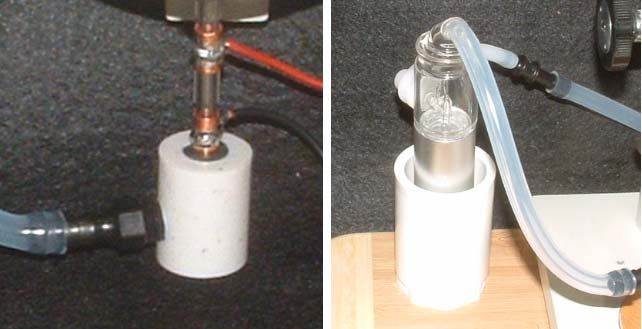
low reflected power (800 mW), high brightness, and a network tuning which could reliably re-
ignite the tube without re-adjustment.

Radiated Noise

One of the mains points of this investigation has been to devise a method of driving a tube using
balanced RF to reduce radiated noise. The relatively high reflected-power when the system is
tuned to allow the tube to be ionised also results in unwanted coax shield current. To combat this,
clip-on ferrites are required to increase the common-mode impedance of the unbalanced
excitation power. It may also be advisable to make the impedance matching network as small as
physically possible to reduce radiation.

Final Configuration

At this point, the multi-ring feed method had only become less appealing because of difficulty in
finding the correct output drive impedance, but it was thought worthwhile to make one last
attempt.

At a purely practical level, it is (obviously) easier to select the optimum feed point from the
output tuned-circuit when there are a large number of turns available to select from. So, using an
air cored coil of small diameter, and larger number of turns has some advantage over a larger coil
with fewer turns.

A new coil was constructed using 10 turns of 1.6 mm copper wire, wound with a final internal
diameter of 13.5 mm, and length of 30 mm. A new feed point was taken on the opposite side of
tuning cap (where there were 9 turns) and from the centre 3 turns.

                                    the Bell Jar, No. 17, April 2021
                                                   4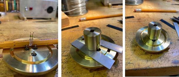
The photograph to the left shows
                                                                       the coil. With the tube in place,
                                                                       the tuning cap (C1) was half-
                                                                       meshed at minimum reflected
                                                                       power, as was the loading cap
                                                                       (C2). The tube would not re-
                                                                       ignite when RF was removed
                                                                       then re-applied.

                                                              Running the system at an
                                                              optimum-match point has several
                                                              advantages including the need for
                                                              minimum excitation power, as
well as minimal radiated power (from the coax screen). Clearly the inability for the tube to
reignite was problematic, and several approaches where considered (including mechanically de-
tuning then retuning the network using a stepper motor).

The final solution was to momentarily ionise the tube using a high voltage spark from a BBQ
igniter (!). I used a Bunnings igniter, SKU 0930747, NZ$20. The spark-gap could be anywhere
along the tube, and with RF applied, a 5 mm spark reliably re-ignites the plasma. The wiring was
re-terminated using 100 mm of PTFE insulated wire, and a spark gap was made by bending the
two wires until they were separated by 5 mm.

The igniter is powered from a single 1.5 volt AA cell, and the unit generates about 3 sparks per
second once energised. This could be part on an automated system if need be.

Closing thoughts

As a side note, it could be useful to find out the load impedance of the ionised tube. One method
that this could be done would be to adjust the energised network for best match/light output, then
replace the power source with a VNA, and replace the tube with a non-inductive variable resistor
adjusted for best return loss. The value of the resistor will then approximate to that of the ionised
tube.

It is hardly surprising that the change in load impedance between the tube’s two states caused
tuning difficulties, these had been anticipated from the start.

                                    the Bell Jar, No. 17, April 2021
                                                   5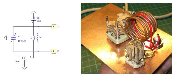
Pretty much all of the tests were carried out using 3 watts of RF. Unsurprisingly, reflected power
was a good measure of energy absorption of the tube. The higher power level was simply not
required during these tests.

7 March 2021

  The above article is published under the Creative Commons Attribution License (cc-by). Re-
  distribution and re-use of this work is on the condition that the creator (Mark Atherton, New
                                Zealand) is appropriately credited.

Additional Thoughts on the Home Made Triode (Triode #1)
Mark Atherton, New Zealand markaren1@xtra.co.nz

Somehow your editor missed including the closing paragraphs from Mark’s article in the last
issue. I’ll blame it on sloppy copy & paste. I’ve included the test data below which did make it
into the prior issue.

The 100uA limit on available anode current was lower than hoped. However, given the large
numbers of unknowns which have gone into the experiment so far it is considered that
fabricating a working triode first go is remarkable.

It is unclear why anode current did not drop further when Vg was raised past –10 volts, there is a
small chance that contamination could be the cause, but would (?) have caused issues during the
vacuum-pumping. It is also possible that electrons were somehow leaking past the grid to the
anode.

Next step will be to reduce overall dimensions. More anode current should be available when the
                                    the Bell Jar, No. 17, April 2021
                                                   6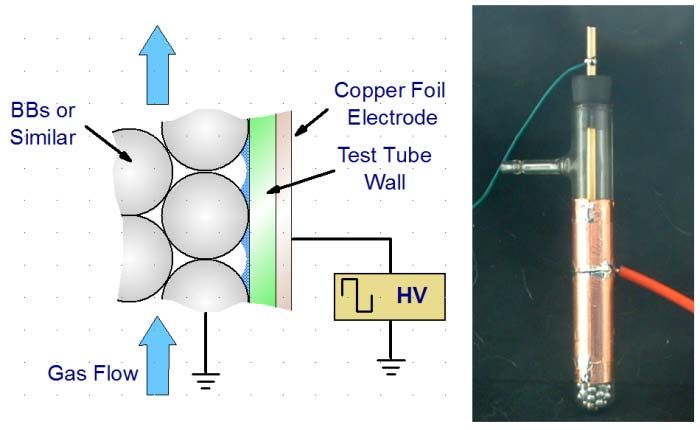
filament and anode electrodes are closer, possibly by the inverse square-law. Another option is to
wrap the anode around the electron source, but this is rather conventional. A third option is to
place an anode either side of the filament.

When Ia reaches a few milliamps, there may be enough available electrons to illuminate some
phosphor sprinkled on the anode plate. One issue with this experiment is that the light from the
bright-emitter may overpower any phosphor illumination. Also, the anode should be held
horizontally, to avoid the phosphor from spilling.

A lab meter will be used in preference to a Fluke 77, set on the 300mA range. This will allow
much higher resolution measurements.

Finally, transconductance measurements above indicate that with Va = 300, and a 56k load, a 5
volt change in grid potential will result in an anode change of just over 1 volt. To increase
voltage gain to unity, the load resistor needs to increase to around 300k.

Targets for next iteration: significantly higher anode current, with Vg = 0. Gain > 10 with RL =
220k.

  The above article is published under the Creative Commons Attribution License (cc-by). Re-
  distribution and re-use of this work is on the condition that the creator (Mark Atherton, New
                                Zealand) is appropriately credited.

Progress on Chuck Sherwood’s Electron Source

Chuck sent along some commentary and photographs regarding his electron source. The emitter
is a single incandescent bulb that is attached to 2 feedthroughs in a shop made brass flange. The
details were discussed last month. The filament is now mounted within a brass Wehnelt cylinder
having a 3/16 inch aperture. This was soldered to the other two feedthroughs. The photographs
below show the bulb (with glass envelope removed) and the assembly process for the Wehnelt
cylinder. The remainder of this article consists of Chuck’s commentary. He may be reached at
chuck1024@wowway.com

                                   the Bell Jar, No. 17, April 2021
                                                  7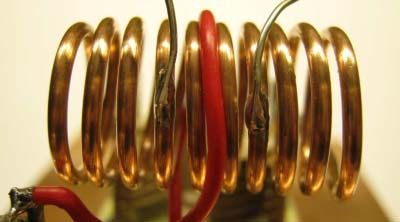
In the photograph at the left below, the setup is under power. This was at about 25 kV. Emission
current was about 100 uA and the bias resistor was about 100k. The tube is blue where electrons
are hitting it, indicating it is not very well focused. Notice the red LED of the Geiger counter. It
just starts to trigger at 25 kV.
As shown in the middle photograph, the holes in the exit flange are now covered with thin
aluminum foil with thickness of 0.0003 to 0.00035 inches. A small metal plate is placed in front
of the foil to measure electron current.
Electrons start to penetrate the foil at 20-25 kV producing 20 nA of current. At 35 kV the current
is up to 100 nA. My very old Keithley 601 Electrometer has no problems measuring these tiny
currents.
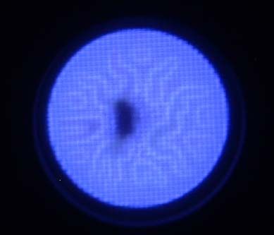
Ionization of air is slightly noticeable at 35 kV. This is shown in the photograph to the right. It
was barely photographable but you can see a small blue spot on one hole. Only light present is
from the flashlight bulb inside the tube. Very little ionization is shown and I determined later that
the holes were nearly completely filled with sealant.
I am having great difficulty attaching foil to the aluminum grid. I have been using Ideal Vac,
"Vac Seal", which looks like clear syrup. If you apply too much, it migrates and completely fills
the holes in the aluminum plate. I tried applying thin circles around the outside perimeter of the
hole circle and even a tiny circle of sealant around each hole. I use a toothpick to apply a thin
line. In both cases, there are leaks large enough to limit the base pressure to about 0.1 micron. I
suspect the root cause is small pin holes in my super thin aluminum foil. I either need to examine
the foil under a microscope to find pin holes and select a good section or use a commercial
product such as a silicon nitride X-ray window from Ted Pella.
The second problem is focusing the electron beam. Only a tiny percentage makes it through the
holes. The blue glow on the sides of the glass tee indicates a lot of electrons are not making it to
the aluminum cap and collecting the current after the aluminum foil indicates a tiny percentage
of electrons are making it through the holes. Large fluctuations in this current also indicate the
internal fields vary a lot and I suspect a lot of electrons are finding a ground path via the Tee side
arm.
So in conclusion this setup has enough issues to consider some major changes. I am tempted to
replace the aluminum foil window with a high tech X-ray window from Ted Pella, but I really
the Bell Jar, No. 17, April 2021
8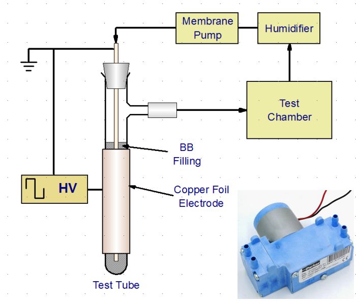
want to use aluminum foil because that is how the famous scientists did it in the past. I think the
key is to build a light box to examine the foil for pin holes and select a good piece and then find
a way to seal it without filling the holes with sealant. It has been suggested to put grooves around
the holes to catch excess sealant and perhaps even try different sealants. Hopefully I will find
something that works..

The Editor Gets a New Power Supply for Atmospheric Pressure Plasmas

It had been on my shopping list for about a year but spending $600 for a driver for atmospheric
pressure plasmas was hard to justify. The supply in question is the PVM500 from Information
Unlimited of Amherst, NH. A few weeks ago I did a search for technical papers that referenced
the supply. I quickly found about 2 dozen in well established technical journals. As a side note,
the papers that reference specific power supplies tend to either name very expensive commercial
function generator/amplifier combinations or proprietary product-specific generators. A smaller
subgroup includes very simple DIY supplies. The PVM500 fits in a middle ground. I sent off my
money and a few days later the package arrived.

The home brew supplies I have been using have mostly been based on fixed frequency
oscillators along with a couple of single ended ferrite core transformers from Information
Unlimited. My favorite is the previously described halogen lamp driver with a Variac along with
the Information Unlimited FLYTCL100 transformer. It operates at a fixed frequency of about 20
kHz. Sometime in the near future I will marry that transformer to my RM Cybernetics pulse
generator module. I expect that will provide similar performance, power wise, to the lamp driver
but with variable frequency and duty cycle capabilities.

The PVM500 comes in a fairly compact no frills package. The controls are simple: oscillator
input voltage (a Variac), frequency, duty cycle and a low/high power switch. There is also a 0-3
amp AC analog meter for the input current. None of the controls is labeled. Frequency range is
20 to 70 kHz. There are also BNC jacks for TTL control and output frequency monitoring
(frequency, not waveform).

The power supply is capable of driving resistive loads, i.e. when the electrodes are in contact
with the gas. The selling point, however, is that the supply is designed primarily for driving
capacitive loads. There are 4 models, each of which has a different transformer secondary. The
secondary used determines the capacitance load range that can be resonated. A nice feature is that
the secondaries may be swapped out, depending on application. The process just consists of
snipping a zip tie, changing the coil and fastening the core together again with another zip tie.
I got the PVM500-1000 which is designed for 5-150 pfd loads. I also got a secondary for
Next came the APPJ. One of the issues with the APPJ has
been sparkover between the two electrodes as they are only
separated by a small gap. This was generally simple to deal
with but required some juggling of the gas flow and voltage.
Tuning the system to resonance tamed the device.

So far, complaints are trivial. Labeled controls would be a
nice touch. There are no rubber feet so the unit slides around
easily. I addressed this with four 1-inch lengths of 1/2” OD
rubber tubing, slit lengthwise and slipped over the inverted
U-channel that makes up the chassis.

https://www.amazing1.com/hv-hf-power-supplies.html

About that “Holiday”

The 2014 Ph.D. dissertation by Klämpfl notes the plasma non-uniformity in a SMD device called
the FlatPlaSter 2.0. In the document there is a considerable amount of discussion on materials for
the electrodes and dielectric, grid pattern, housing, getting discharge uniformity, etc.. Well worth
examining just for that. I’m looking at substituting a perforated stainless sheet for the wire mesh.

Tobias Gabriel Klämpfl, Cold atmospheric plasma decontamination against nosocomial bacteria,
Ph.D. thesis, 2014.
https://www.researchgate.net/publication/261134070_Cold_atmospheric_plasma_decontaminatio
n_against_nosocomial_bacteria

A Simple Afterglow SMD Device

In last month’s issue I wrote a bit about biological decontamination using the plasma afterglow
of a surface micro-discharge (SMD) plasma device. This was based on a paper by Müller et al.
[1]. The experimental apparatus utilized a continuous circulation scheme where the plasma
source and test chamber are in a closed loop along with a simple humidifier and membrane pump.

In the paper, the SMD plasma was generated by a grounded spring with a tight fit inside a quartz
tube. The high voltage electrode was outside the tube. The SMD plasma was formed on the
inside of the tube where the air flowing though the tube became activated. To quote: “Only stable
species with a long lifetime, e.g. O3 , H2O2 and NO2 are able to reach the target. This cocktail of
long-lifetime plasma species is called ‘plasma afterglow’ and is predominant for the treatment of
targets located at a certain distance from the plasma source.” The researchers also found that an
inline humidifier improved the performance of the device with regard to the effect on
microorganisms. A simple bubbler served to provide 90% relative humidity.

I suggested that, instead of the tight-fitting spring, steel BBs might be used. It just happened that
I found a tube of Daisy “you’ll shoot your eye out” BBs in a kitchen drawer. I’m not sure why I
had them as all of my airguns shoot lead pellets. I made a SMD device using a 15 mm side-arm
test tube, a 7” length of 3/16” diameter brass tubing as a dip tube and a #1 1-hole rubber stopper.
                                     the Bell Jar, No. 17, April 2021
                                                   10
The outer electrode is made using adhesive copper foil. The inner (ground) electrode is, of course,
the BBs and contact is made through the dip tube. The illustration below show how the discharge
is formed along with a photograph of the test tube plasma afterglow source.
The tube is about 5-3/4 inches long and the copper foil covers the lower 3-1/2 inches. I ended up
only filling the tube to about ½ inch below the top of the outer electrode. I had more (almost up
to the side arm) initially but it cut down the gas conductance considerably.
The sketch on the next page is based on the recirculating device in the reference. I have a little 12
volt diaphragm pump that should work well. This is shown in the inset. This is a Parker D1001-
23-01 2 stage pump rated at 2.5 l/min per stage, The stages may be paralleled to double the
volume or placed in series to double the pressure. This one cost about $20 on eBay. The
humidifier could simply be another test tube with dip tube, replacing the BBs with water. The
test chamber just needs to be able to be sealed, have an inlet and outlet and be of appropriate size.
It works very well with the PVM500 power supply but also produces a reasonably pungent
output with my lamp driver and FLYTCL100 transformer. The configuration in the paper
includes an FTIR spectrometer for gas analysis but that’s beyond the typical amateur’s means.
Additional information on SMD plasma devices may be found on the Terraplasma GmbH
website [2]. The site also has listings of relevant papers and patents on SMD applications.
While not using using a recirculating arrangement, there is an interesting paper by Mitra et al. [3]
related to the cold atmospheric pressure treatment of seeds. From the abstract:
Sustaining the quality of seeds is a major task in attempting to supply nutrition to the
growing world population. In this study, the seeds of Cicer arietinum (chickpea) were
exposed to cold atmospheric plasma (CAP). A significant reduction of the natural
microbiota attached to the seed surface was observed for increasing CAP treatment
times—2 and 5 min were sufficient to achieve a 1 and 2 log reductions, respectively.
the Bell Jar, No. 17, April 2021
11Furthermore a 1 min
CAP treatment showed a strongly improved seed germination (89.2 %), speed of
germination (7.1±0.1 seeds/day), and increased seed vigor, beside a decrease in the mean
germination time (2.7 days) compared with controls. The roughness profile of the seed
cotyledon was altered significantly, only in case of longer treatment times from 5 min.
These results suggest that CAP technology has the potentiality to reduce health risks
associated with contaminated seeds, while improving food quality.
Germination studies with CAP would seem to be a good area for student and amateur
investigations, perhaps even using the recirculating scheme.
References
1. Meike Müller, Tetsuji Shimizu, Sylvia Binder, Petra Rettberg, Julia L. Zimmermann, Gregor
E. Morfill, and Hubertus Thomas, Plasma afterglow circulation apparatus for
decontamination of spacecraft equipment, AIP Advances 8, 105013 (2018).
https://www.researchgate.net/publication/328208243_Plasma_afterglow_circulation_apparat
us_for_decontamination_of_spacecraft_equipment
2. https://www.terraplasma.com/en/
3. Anindita Mitra, Yang-Fang Li, Tobias G. Klämpfl, Tetsuji Shimizu, Jin Jeon, Gregor E.
Morfill and Julia L. Zimmermann, Inactivation of Surface-Borne Microorganisms and
Increased Germination of Seed Specimen by Cold Atmospheric Plasma, Food Bioprocess
Technol (2014) 7:645–65. Open access: https://link.springer.com/article/10.1007/s11947-
013-1126-4
Adding a Nebulizer to the APPJ
In the September 2020 issue I presented a sketch of my APPJ with a modified compression tee at
the outlet. This was to permit the addition of a monomer to the plasma plume for deposition
the Bell Jar, No. 17, April 2021
12purposes. I abandoned this as it just seemed that the tee, made for 1/4” tubing, would be too long
and too restricting.
I then set out to make a simple Teflon adapter. This would be shorter and provide more area at
the tube’s exit. Plus, I love to machine Teflon. The scaled figure below shows the end result.
The applicator is fashioned from a piece of 7/8” diameter PTFE cut to 1-1/8” in length. I bored a
¼ inch diameter hole along the axis. This was sized to just pass the 6 mm quartz capillary. To
retain the capillary I made a 1/4” deep recess into which I could squeeze a piece of 1/4” ID x
7/16” OD Norprene (Tygon) tubing. Since the capillary easily slides through the tube, I made the
hole undersized – 27/64” in diameter, i.e. 1/64” less than the Norprene tube’s OD. This makes for
a tight fit and it holds the capillary quite firmly.
At the other end I bored a 3/8” diameter hole deep enough such that the 1/4” connecting section
was just under 1/4” in length. To complete the applicator, I drilled and tapped a hole in the side
for 1/8” pipe thread. This was positioned such the aerosol exit would be in close proximity to the
end of the capillary.
On the capillary I placed the 3/8” wide copper foil ground electrode ½” from the exit. The driven
electrode was placed to provide a ½” gap between the electrodes. When inserted into the
applicator, the ground electrode is flush with the Norprene gland and the tip of the capillary is
roughly flush with the widened mixing region.
For the nebulizer, I ended up using the one I showed last month. As advertised on eBay, the
complete unit is described as a “Portable Nebulizing Diffuser Waterless Diffuser for Essential
Oils Aromatherapy” item 224042322641 and sold by TwoScents. It came with 2 nebulizers but
no bottles. I had to order a pack of 5 bottles and caps from the same seller.
Modification of the unit was easy. I basically threw everything away except for the nebulizer
assembly and the elastomer air fitting into which the nebulizer fits. There is a nice little 2.5 l/m
air pump that runs from a USB port that I kept.
the Bell Jar, No. 17, April 2021
13The nebulizer fits nicely into a piece of 1” PVC pipe. I made a support from 1” fittings and
screwed that to the base of my APPJ jet assembly. The photographs below are close-ups of the
APPJ/applicator assembly and the nebulizer.
I am using argon as the jet and carrier gas. Regulation is provided by two oxygen rotameters (aka
variable area flow meters). The APPJ uses a 20 slm unit and the nebulizer is driven by a 5 slm
unit. To get an approximation of the actual argon flow, the indicated flow has to be multiplied by
a correction factor. For an air rotameter, the multiplier is 0.85. For an oxygen unit, the multiplier
is 0.90. For helium the actual flow rates are just under 3X the reading. Brooks Instrument and
Cole Parmer, among others, have tables of conversion factors on their web sites.
The photograph on the next page shows the completed set up. As noted in a prior issue, the APPJ
is mounted on a microscope stand. Electrical connections are on the right. Fastened to the HV
standoff is a Tektronix P6015A high voltage probe. This is pretty much the standard for
monitoring the waveforms of this type of device. The oscilloscope is at the rear. The two
rotameters are mounted to the shelf and the PVM500 power supply is at the upper right.
On the left is the nebulizer with a silicone tubing connection to the applicator. I was a bit
concerned that the aerosol would condense and dribble out of the tube but, so far, I’m not seeing
any droplet formation when using the essential oil linalool. I have considered adding an inline
heated section to vaporize the aerosol.
I also have a couple of Pearson current transformers but those are not shown.
At the top left is a syringe pump for future liquid delivery efforts. The vacuum part of my stand
is to the right, mostly out of the picture.
the Bell Jar, No. 17, April 2021
14The next step will be to see if I can actually deposit a film. In the
meantime, to the right is the obligatory picture of the plasma plume
playing on my finger. Gas flow was about 5 liters per minute.
Articles of Possible Interest in Vacuum Technology & Coating Magazine
April 2012
Hot Wires and Fast Molecules: A Different Look at Pirani Gauges
Heat transfer and theory behind Bruce Kendall’s Glow Plug Pirani gauge.
May 2012
Going to Extremes: Exploring the upper and lower bounds of the Pirani gauge’s response
Conventional Pirani gauges and how MEMS Pirani gauges can measure pressure to 10-5 Torr and
also measure pressures between 100 and 1000 Torr without the convection effect.
the Bell Jar, No. 17, April 2021
15December 2014 and January 2015
Mean Free Path and the Vacuum Gauge
The December 2014 column covers Pirani gauges. The January 2015 column covers ion total and
partial pressure gauges.
Articles may be accessed at http://vtcmag.com/. Scroll to the bottom of the page to the back issue
selection box. Look for my columns and you can probably find other articles of interest in each
issue.
End Notes
I want to thank Mark and Chuck for their ongoing vacuum oriented contributions. Aside from the
atmospheric pressure work, I am also moving forward on refining my saddle field ion and atom
source. There will be some updates on that in the next issue.
As usual, comments and contributions are welcomed.
Steve
the Bell Jar, No. 17, April 2021
16You can also read