Strategies for Reducing the PGM Loading in High Power AEMFC Anodes - IOPscience
←
→
Page content transcription
If your browser does not render page correctly, please read the page content below
Journal of the Electrochemical
Society

OPEN ACCESS

Strategies for Reducing the PGM Loading in High Power AEMFC
Anodes
To cite this article: Travis J. Omasta et al 2018 J. Electrochem. Soc. 165 F710

View the article online for updates and enhancements.

                                This content was downloaded from IP address 46.4.80.155 on 08/02/2021 at 15:16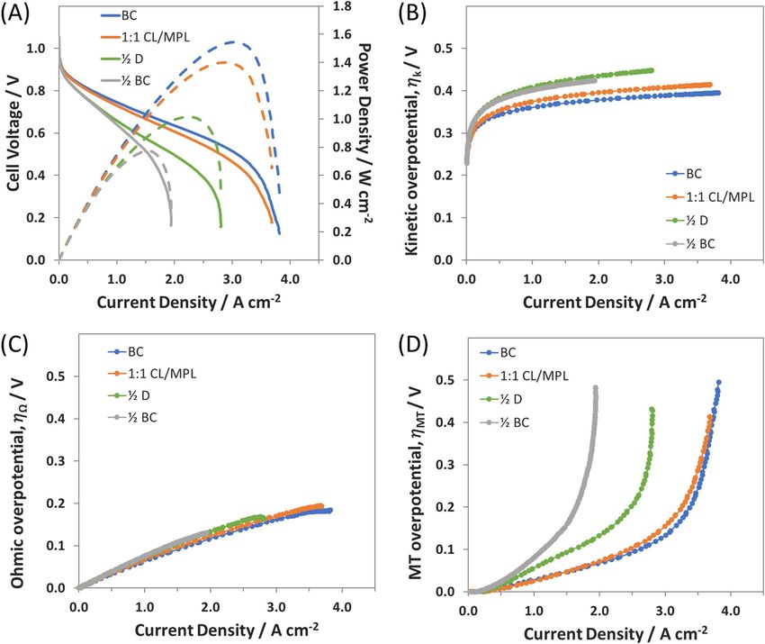
F710                                           Journal of The Electrochemical Society, 165 (9) F710-F717 (2018)

                             Strategies for Reducing the PGM Loading in High Power AEMFC
                             Anodes
                             Travis J. Omasta, 1,2,∗ Yufeng Zhang,2 Andrew M. Park,3,∗∗ Xiong Peng,1,2,∗
                             Bryan Pivovar,3,∗∗ John R. Varcoe,4,∗∗ and William E. Mustain 1,2,∗∗,z
                             1 Department     of Chemical Engineering, University of South Carolina, Columbia, South Carolina 29208, USA
                             2 Department of Chemical & Biomolecular Engineering, University of Connecticut, Storrs,    Connecticut 06269, USA
                             3 National Renewable Energy Laboratory, Golden, Colorado 80401, USA
                             4 Department of Chemistry, University of Surrey, Guildford GU2 7XH, United Kingdom

               Anion Exchange Membrane Fuel Cells (AEMFCs) have experienced a significant rise in attention in recent years, largely motivated
               by the potential to overcome the costs that have plateaued for proton exchange membrane fuel cells. However, despite significant
               advances in power generation, membrane conductivity, membrane stability, and catalyst activity, the vast majority of high performing
               AEMFCs are fabricated with a high PGM loading (0.4–0.8 mg cm−2 ). This work demonstrates an electrode fabrication method that
               reduces the anode catalyst loading by 85% while still achieving performance ca. 1 W cm−2 – accomplished by designing a multi-
               layered electrode comprised of an optimized ionomer:carbon:PGM ratio catalyst layer coupled with a hydrophobic microporous
               layer. If paired with a high-performing PGM-free cathode, this new anode shows the potential to meet existing DOE PGM loading
               and performance targets.
               © The Author(s) 2018. Published by ECS. This is an open access article distributed under the terms of the Creative Commons
               Attribution 4.0 License (CC BY, http://creativecommons.org/licenses/by/4.0/), which permits unrestricted reuse of the work in any
               medium, provided the original work is properly cited. [DOI: 10.1149/2.1401809jes]

               Manuscript submitted April 24, 2018; revised manuscript received June 13, 2018. Published June 21, 2018. This was Paper 1754
               presented at the Seattle, Washington Meeting of the Society, May 13–17, 2018.

    Anion exchange membrane fuel cells (AEMFCs) have received                        ionomer:carbon:catalyst ratio all have a significant effect on the water
significant attention in recent years as a potentially lower cost electro-           content and balance of the overall cell.
chemical energy conversion device than proton exchange membrane                          In this study, the influence of anode catalyst layer thickness and
fuel cells (PEMFCs).1–3 There have been several major advancements                   catalyst distribution in lower loading electrodes is investigated, with
in the materials and operational understanding of the AEMFC in the                   the goal of decreasing PGM loading without sacrificing performance.
past few years, which have allowed AEMFCs to close the performance                   Several approaches are tried, including thinner catalyst layers, dilut-
gap with PEMFCs. Improvements in membrane stability and conduc-                      ing the catalyst in the active layer as well as introducing multi-layered
tivity have been at the forefront of the material improvements, with                 electrodes with a microporous layer (in various thickness ratios). The
conductivities rivaling Nafion,4–10 and an increasing number of mem-                 resulting catalyst layers are analyzed through their achievable current,
branes showing stability in highly alkaline environments (up to 2 M                  peak power density, electrochemical surface area, hydroxide transport
KOH at 80◦ C) for 100s or even 1000s of hours.8–13 Additionally, cat-                resistance, as well as kinetic and mass transport reaction overpoten-
alyst layer engineering that allows for improved water management,                   tials. Finally, performance and stability of the catalyst layers with de-
both on the macro-scale14 and on the micro-scale,15 has led to AEM-                  creased platinum group metal (PGM) loading will be shown, demon-
FCs that are able to achieve peak power densities nearing 2 W cm−2                   strating an anode electrode, that when paired with a PGM free anode,
and demonstrate operational stability exceeding 500 hours. These are                 could potentially meet DOE loading and performance targets.
crucial steps toward the realization of commercially viable AEMFCs;
however, there remain additional hurdles to overcome, specifically
AEMFCs with low platinum group metal (PGM) loadings that are                                                      Experimental
able to not only achieve high power densities but sustain them over                      Ethylene tetrafluoroethylene (ETFE-BTMA) membrane
long term operation.12                                                               synthesis.—The membrane used in this study was a quaternary
    In order to reduce the PGM loading in operating AEMFCs, there                    ammonium functionalized ETFE polymer, prepared from commercial
will need to be at least some development of non-PGM catalysts. Due                  25 μm ETFE sheets (Nowofol Kunststoffprodukte GmbH, Germany)
to differences in the water dissociation behavior in alkaline media,16               using a peroxidation (pre-irradiation in air) method that has been
the kinetics for the hydrogen oxidation reaction are hindered in al-                 previously reported.6 The ETFE films were first subjected to a 30
kaline media compared to acid media.17 The opposite is true of the                   kGy dose of electron-beam irradiation in air (4.5 MeV Dynamatron
oxygen reduction reaction at the cathode; therefore, it is more likely               Continuous Electron Beam Unit at Synergy Health, South Marston,
that the AEMFC will see a high performance PGM-free cathode                          UK). With the irradiation step occurring in the presence of oxygen,
electrode. Indeed, some very promising catalysts have already been                   peroxides and hydroperoxide groups are immediately created from
identified.3,18–23 However, at the AEMFC anode, it is very likely (akin              the reaction of radicals (formed during irradiation) with O2 . The
to the PEMFC cathode) that it will be difficult to move completely                   peroxidated ETFE films act as a solid-state free-radical initiator
away from PGM-based catalysts, though this is presently an active                    for the subsequent grafting step. After irradiation, the films were
area for research.24,25 Therefore, it is important for researchers in the            transported back to the laboratory in dry ice before they were stored
field to investigate electrode compositions that allow for reduced cat-              in a freezer at −40◦ C (the peroxide groups are stable for around 6
alyst loading – the most active hydrogen evolution catalyst known                    months at this temperature).27
today is PtRu26 – while still allowing for the water produced dur-                       Next, the peroxide initiated ETFE films (ca. 15 cm × 15 cm) were
ing the hydrogen oxidation to be properly managed, a crucial step in                 immersed in an aqueous dispersion of VBC (vinylbenzyl chloride, 5
the successful operation of AEMFCs.3,14,15 Properties of the catalyst                vol% mixture of 3- and 4-isomers; 500 – 100 ppm tert-4-butylcatechol
layer such as structure, thickness, porosity, component chemistry, and               and 700 – 1100 ppm nitromethane inhibitors, Sigma-Aldrich and
                                                                                     used without the removal of inhibitors) in sealed vessels along with
                                                                                     the addition of a dispersant (1 vol% 1-octyl-2-pyrrolidone, Sigma-
  ∗ Electrochemical Society Student Member.                                          Aldrich). The solutions were purged with N2 for 2 h before the vessel
 ∗∗ Electrochemical Society Member.                                                  was sealed and heated at 70◦ C. After the reaction period, the films were
  z
    E-mail: mustainw@mailbox.sc.edu                                                  removed from the grafting mixture and excess unreacted VBC and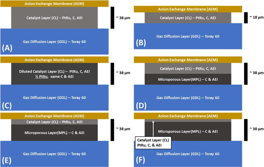
Journal of The Electrochemical Society, 165 (9) F710-F717 (2018)                                    F711

any poly(VBC) homopolymer (not bound to the ETFE base material)           was approximately seven times the CL thickness and is denoted as
were removed by washing the films in toluene (reagent grade, Fisher       “1:7 CL/MPL”.
Scientific). The resulting intermediate ETFE-g-poly(VBC) films were           Therefore, six distinct anode electrode compositions were pro-
subsequently dried at 70◦ C for 5 h in a vacuum oven to remove all        duced – 2 two “single layer” electrodes, 1 “diluted” electrode and
traces of solvent.                                                        3 “multilayer” electrodes. For each of the six compositions, a min-
    To quaternize, the intermediate films were then submerged in an       imum of three identical anodes were tested, and representative data
aqueous trimethylamine solution (TMA, 45 wt%, Sigma-Aldrich) for          is reported in each case. For clarity, illustrations of each of the six
24 h at ambient temperature. Afterwards, the films were washed            electrodes are shown in Figure 1. The catalyst loading and thick-
with, and then heated in, 18.2 M deionized (DI) water in order           ness (measured at 5 locations per electrode with a micrometer, Mi-
to remove any excess TMA. Final conversion to chloride-anion-form         tutoyo MDC-SX) of each electrode are given in Table I. For all
ETFE-g-poly(vinylbenzyl trimethylammonium) (ETFE-BTMA) an-                experiments, the cathode was essentially identical. The cathode Pt
ion exchange membranes (AEMs) was performed by submersion of              loading was 0.52 mg cm−2 ± 0.01 mg cm−2 , with an AEI:C:Pt of
the membranes in aqueous NaCl (1 M) for 15 h (with a change of            0.625:1.5:1.0.
NaCl solution during this period to ensure complete ion-exchange).
The resulting AEMs were then thoroughly soaked and rinsed in water            Electrode preparation.—The procedure to prepare the CL was al-
to remove any excess NaCl-derived co- and counter-ions. The final         ways the same, regardless of the composition. An example of prepar-
AEM(Cl− ) films were stored in DI water until used in the fuel cell       ing a BC film follows. First, the AEI powder was ground with a mortar
experiments described below.                                              and pestle for 10 min to reduce the number of aggregated particles.
                                                                          Second, 100 – 150 mg of 60 wt% PtRu (2:1 ratio of Pt:Ru by mass) on
                                                                          Vulcan carbon (Alfa Aesar HiSPEC 10000, Pt nominally 40 wt%, and
    Anion-exchange ionomer (AEI) powder synthesis.—The synthe-
                                                                          Ru, nominally 20 wt%, supported on Vulcan XC-72R carbon) cata-
sis of the powdered AEI is summarized here and has been previously
                                                                          lyst was added to the AEI along with 1 mL DI water and additional
reported in detail.28 ETFE powder (Z8820X, AGC Chemicals Europe)
                                                                          Vulcan carbon to achieve the desired AEI:C:PtRu ratio. The catalyst-
with a particle size of approximately 25 μm was dosed with 70 kGy
                                                                          AEI mixture was then ground with a mortar and pestle for 10 min, a
electron-beam radiation in air. The resulting powder was then grafted
                                                                          length of time that was selected because it invariably produced a visu-
with VBC by submersion in a solution containing VBC, 2-propanol
                                                                          ally and texturally homogenous slurry, suggesting that no large AEI
(reagent grade, Sigma-Aldrich), and Surfadone LP-100 (ISPcorp) in
                                                                          agglomerates remained. Then, 2 mL of 2-propanol (Fisher Chemical
a volume ratio of 1.00:3.95:0.05. The mixture was purged with N2
                                                                          Optima) was added to the mortar and ground for a further 5 min, after
for 2 h, and then sealed and heated for 72 h at 60◦ C. The result-
                                                                          which the catalyst slurry was completely transferred to a LDPE vial,
ing grafted powder was recovered by filtration, washed with toluene
                                                                          and combined with an additional 7 mL of 2-propanol to produce a low
(reagent grade, Fisher Scientific), and dried at 50◦ C under vacuum,
                                                                          viscosity ink. Each ink was homogenized in an ice-chilled ultrasonic
resulting in ETFE-g-poly(VBC) grafted powders. The powder was
                                                                          bath (Fisher Scientific FS30H) for 60 min, maintained between 5◦ C
then quaternized by submersion in an aqueous TMA solution (50
                                                                          and 10◦ C. The resulting inks were spray deposited onto a 25 cm2
wt% TMA in water, Acros Organics) for 5 h at ambient tempera-
                                                                          piece of Toray TGP-H-060 GDL (with 5 wt% PTFE wetproofing)
ture. The quaternized powder was washed 5 times with DI water,
                                                                          to fabricate gas diffusion electrodes (GDEs), using an Iwata Eclipse
and then heated at 50◦ C for 18 h in DI water. After additional wash-
                                                                          HP-CS with 15 psig N2 (Airgas Ultra High Purity). 5 cm2 GDEs
ing steps (5 more times with DI water), the powder was dried un-
                                                                          were then cut from the larger sprayed electrode for use in the cell
der vacuum for 5 d at 40◦ C. The final AEI powder had an IEC of
                                                                          hardware.
1.24 ± 0.06 mmol g−1 .
                                                                              MPL inks were created using the same method described above,
                                                                          simply without the catalyst. The AEI:C mass ratio in the MPL ink
    Electrode composition and structure.—Three different types of         was 0.417:1.0. The MPL film was also sprayed using an Iwata Eclipse
anode catalyst layers (CL) were fabricated in this work: 1) A single      HP-CS with 15 psig N2 (Airgas Ultra High Purity). In the case where
layer electrode with a “balanced” AEI:carbon:PtRu mass ratio15 of         the electrode had a MPL, the MPL was applied to the GDL first and
1.0:2.5:1.5; two anodes of this type were made. The first possessed a     allowed to dry. This was followed by deposition of the CL using the
PtRu catalyst loading and thickness typical of top performing AEM-        process described above.
FCs in the literature, 0.72 mgPtRu cm−2 (denoted as BC). The second
anode of this type had approximately half of the PtRu catalyst load-         MEA assembly and anion exchange membrane fuel cell
ing (0.40 mg cm−2 ) and thickness (denoted as “ 12 BC”); 2) A single      (AEMFC) testing.—First, the GDEs and the AEM were ion ex-
layer electrode with a “diluted” CL that was designed to have the         changed from the Cl− form to the OH− form by immersion in sep-
same loading as 12 BC, but the same thickness as BC. This was ac-         arate baths of aqueous KOH (1 M, Fisher Chemical, pellets/certified
complished by adding Vulcan XC-72R (Cabot) to the ink in order to         ACS) for 60 minutes, with a solution exchange every 20 minutes to
achieve an AEI:C:PtRu ratio of 1.0:2.5:0.75. Only one anode of this       ensure complete ion-exchange. It should be noted that during the ion-
type was made; it is denoted as “ 12 D”; and 3) multilayered electrodes   exchange process nearly no particles were removed from the GDEs,
consisting of a catalyst layer (in contact with the membrane) and a       verifying successful adhesion of the CL and MPL films to the GDL.
microporous layer (MPL) located between the catalyst layer and the        Prior to assembly, excess aqueous KOH and water were removed from
gas diffusion layer (GDL). The MPL was comprised of AEI and Vul-          the membrane and GDEs, immediately after which the set of GDEs
can carbon in the following mass ratio, 0.417:1.0. Three anodes of        and AEM were pressed together between two single pass serpentine
this type were made. All of them were designed to have the same           graphite plates in 5 cm2 Fuel Cell Technologies hardware with no
approximate thickness as the BC and 12 D anodes. The difference be-       prior hot pressing of the membrane electrode assembly (MEA). The
tween them was the ratio of the catalyst layer thickness and the MPL      MEA was sealed and compressed with 6 mil (152 μm) PTFE gaskets
thickness. The first anode of this type had a catalyst layer that was     with 20%–25% pinch at 5.1 N·m torque.
the same as the 12 BC anode; hence the MPL thickness was approx-             Humidified H2 and O2 gas feeds were supplied to the anode and
imately the same as CL thickness and this case will be denoted “1:1       cathode, respectively, at 1.0 L min−1 from a Scribner 850e Fuel Cell
CL/MPL”. The second anode of this type also had an electrode with         Test Station, which was used for all testing. The gas feeds were pro-
the same composition as BC but was only 14 of the loading; hence the      vided without back pressure (ca. 1 atm absolute). In each experiment,
MPL thickness was approximately three times the CL thickness and is       the dew points of the anode and cathode reacting gases were opti-
denoted as “1:3 CL/MPL” in the discussion below. The third and final      mized, which was achieved by iteratively adjusting the anode and
anode of this type again had an electrode with the same composition       cathode dew points approximately every 10 minutes, allowing the cell
as BC, but only possessed 18 the loading; hence the MPL thickness         to equilibrate, and observing the cell response. The optimized dew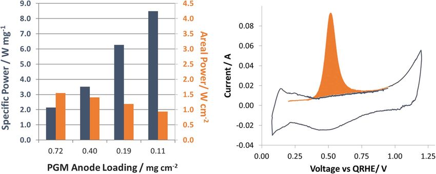
F712                                       Journal of The Electrochemical Society, 165 (9) F710-F717 (2018)

Figure 1. Diagram of the electrode layer designs used in this study: A) Standard (BC); B) 12 thick BC ( 12 BC, reduced loading, standard AEI:C:Pt ratio, reduced
thickness) C) 12 Diluted ( 12 D, reduced loading, reduced AEI:C:Pt ratio, standard thickness); and Multilayer electrode (reduced loading, standard AEI:C:Pt ratio,
thickness supplemented with MPL) in D) 1:1 CL/MPL, E) 1:3 CL/MPL, and F) 1:7 CL/MPL ratios.

points were selected where power and current density were maxi-                         Measuring the electrochemically active surface area of the PtRu
mized without sacrificing membrane hydration, which is indirectly                   electrodes.—CO stripping was used to measure the electrochemical
measured by the test station in two ways: current interrupt and mea-                surface area (ECSA) of all electrodes after they were loaded into the
suring the high frequency resistance (HFR). The optimized dew points                AEMFC hardware. In this technique, humidified pure CO gas is fed
are reported in an Anode/Cathode format. For example, noting dew                    to the PtRu/C working electrode and H2 gas is fed to the Pt/C counter
points of 56/58 would correspond to an anode dew point of 56◦ C and                 electrode. CO adsorbs as a full monolayer on the electrode surface
a cathode dew point of 58◦ C. A cell temperature of 60◦ C ± 0.1◦ C was              at low potential. The gas at the PtRu/C electrode is switched to N2
used for all experiments and the heated gas lines following the Scrib-              in order to flush out any excess gas-phase CO. Then, the electrode
ner 850e Fuel Cell Test Station were held at 5◦ C above the respective              potential is swept in the positive direction to oxidize the CO to CO2 .
gas dew points to avoid any condensation in the lines.                              The area under the curve in the resulting voltammogram can be directly
    All of the polarization curves shown were collected under poten-                linked to the quantity of CO, and hence the area that CO previously
tiometric control at a scan rate of 10 mV s−1 . Linear sweeps – in lieu of          occupied on the surface.
point-by-point collection – were used in order to better tease out flood-               Here, 0.2 L min−1 CO was passed over the PtRu working electrode
ing issues under water starved and flooded conditions. When water                   for 10 minutes while 0.2 L min−1 H2 was continuously passed over the
management issues are well controlled, there is no significant differ-              Pt/C counter electrode. During the flow of CO, the PtRu/C electrode
ence between point by point and linear sweep polarization curves,                   potential was held at a potential of 0.2 V vs the counter electrode in
which was shown in our previous work for multiple high performing                   order to ensure that none of the surface CO was oxidized, allowing
cells.14,15 Additionally, tests were repeated after multiple hours and              for complete adsorption of CO on all active sites. Following CO
varying the testing conditions to ensure stability, recoverability, and             adsorption, N2 was purged for 30 minutes, and cyclic voltammograms
repeatability.                                                                      were collected between 0.07 and 1.2 V for three cycles at 20 mV/s.

   Table I. Loadings and Dew Points of all cells tested in the manuscript.

                                                                  1                 1
             Anode Type:                        BC                2   BC            2   D            1:1 CL/MPL              1:3 CL/MPL              1:7 CL/MPL
   Anode PtRu Loading, mg     cm−2               0.72              0.40              0.40                0.40                    0.19                    0.11
   Cathode Pt Loading, mg cm−2                   0.53              0.53              0.53                0.53                    0.52                    0.52
                                                                                                           1                       3                       7
   MPL, fraction of electrode                      -                 -                 -                   2                       4                       8
   Thickness, μm                               38 ± 1            18 ± 1            38 ± 1               38 ± 1                  38 ± 1                  38 ± 1
   Optimized Dew Points,◦ C                     47/48             53/53             50/51                46/47                   50/50                   52/53
Journal of The Electrochemical Society, 165 (9) F710-F717 (2018)                                          F713

CO was fully stripped from all electrochemically active platinum sites          cell electrodes containing high activity catalysts with good utilization.
during the first cycle. The areal difference between the first and second       The ohmic overpotential (Figure 2C) shows the expected behavior of
cycle (in Watts) was then used to calculate the electrode ECSA.                 AEMFCs, with a slight decreasing slope with increasing current. This
                                                                                change in the slope is caused by increased ionic conductivity in the
                                                                                membrane, which is facilitated by increased water uptake as the anode
      Quantitative Analysis of AEMFC Polarization Curves
                                                                                water production increases with increasing current from the hydrogen
    As the electrode composition is varied, it is important to understand       oxidation reaction (Equation 5).
not only how these changes are manifest in the cell performance, but
also in fundamentals: kinetics, ohmic resistance and mass transport.                                H2 + 2O H − → 2H2 O + 2e−                         [5]
Though several methods have been proposed in the literature to de-
convolute polarization curves into these constituents, one of the most              Finally, the mass transport overpotential gradually increased with
straightforward methodologies to apply was published by Gasteiger               the current density until the cell passed 3 A cm−2 , indicating a low
et al.29 in 2004. Their approach was adapted for use in this work,              hydroxide transfer resistance in the catalyst layer, and successful water
which is briefly described below.                                               management – both of which allow the cell to achieve higher currents
    If the polarization of an operating fuel cell is assumed to be a result     and, in turn, higher power densities. After 3 A cm−2 , the mass transport
of only kinetic, ohmic, and mass transfer phenomena, the operating              overpotential became the dominating contributor to cell polarization,
cell voltage at any current can be represented by:                              as well as the achievable current and peak power. The goal of this
                                                                                study was to drastically lower the catalyst loading, while retaining
                     E cell = Er ev − η − ηk − ηMT                      [1]    current and power densities as close to state-of-the-art BC as possible.
where Ecell is the operating cell voltage, Erev is the thermodynamic                The first attempt to lower the PGM catalyst loading was the 12
reversible cell potential (1.20 V), and η , ηk , and ηMT represent the         BC anode, fabricated with an identical CL composition as the BC
ohmic, kinetic, and mass transfer overpotentials, respectively. The first       electrode, at approximately half the loading and thickness (Figure
step to extracting each of the overpotentials in Equation 1 is to isolate       1B). It would be expected that this method would greatly sacrifice the
the ohmic overpotential, which can be directly calculated at each point         water capacity of the catalyst layer, making the cell more sensitive to
on the curve from the product of the high frequency resistance (RHFR )          water and more susceptible to flooding. Looking at the i-V and i-P
– which is measured by a frequency response analyzer built into the             curves for the 12 BC electrode in Figure 2A, it is clear that reducing the
Scribner fuel cell test stands – and the operating current (i), as shown        catalyst layer thickness has a negative effect on both the achievable
in Equation 2:                                                                  current density (now < 2 A cm−2 – less than half the value of the BC
                                                                                anode) and peak power density (only 0.8 W cm−2 – also half the value
                               η = i RHFR                               [2]    of the BC anode).
    The next step is to extract the kinetic overpotential, which can be             Deconvolution of the 12 BC anode polarization curve showed near
done at cell voltages greater than 0.85 V and operating currents less           identical ohmic overpotentials (Figure 2C), and a slight increase in
than 100 mA cm−2 under the assumption that mass transfer limitations            the kinetic overpotential (Figure 3B) compared to the BC anode. The
are negligible in that region.29 Under these conditions, Equation 1 can         most notable change when comparing the 12 BC and BC anodes is
be simplified and the resulting data fit by the Tafel equation as shown         the significant increase in the mass transfer overpotential (Figure 3D)
in Equation:                                                                    over the entire current range. At higher currents, the increased mass
                                                                                transport resistance is not too surprising since the decreased water
                Er ev − E cell − η = ηk ∝ a + b∗ log(i)                 [3]    capacity of the anode would make it more susceptible to flooding.
where b is the Tafel slope. The final step of the deconvolution is to           However, it was somewhat surprising that the mass transport resistance
calculate the mass transfer overpotential, which is done by subtracting         at low current densities, which shows the resistance to ionic movement
the kinetic and ohmic overpotentials from the reversible cell potential         in the catalyst layers also decreased. This suggests that hydroxide
at all current densities:                                                       transport at the cathode in the 12 BC cell is suffering. In short, the
                                                                                same reduced water capacity of the 12 BC anode compared to the BC
                         ηMT = Er ev − η − ηk                           [4]
                                                                                anode that is responsible for premature flooding also can limit the
    It should be noted that in this method the cell polarization due            amount of water that is absorbed by the membrane and hence amount
to hydroxide transport resistance within the catalyst layer is included         of water that is supplied to the cathode. Experimental support for
in the mass transfer overpotential. It shows itself in the experimen-           reduced membrane water and reduced water transport to the cathode
tal data as the initial slope before the mass transport limiting current        are higher membrane resistance for 12 BC compared to BC (Figure
is approached. Often the electrode hydroxide transfer overpotential             2C) as well as the higher dew points that were needed to optimize the
would be considered a component of the ohmic overpotential; how-                cell performance (Table I). In summary, comparing the BC and 12 BC
ever, explicitly accounting for it requires an AC impedance frequency           anode suggests that simply decreasing the CL thickness might not be
sweep to measure, a technique that is not practical during a dynamic            the most productive way to decrease the catalyst loading. Therefore,
polarization experiment.                                                        pathways to decrease loading while maintaining the catalyst layer
                                                                                thickness were explored.
                        Results and Discussion
                                                                                    Reducing the catalyst loading while maintaining the electrode
    Reducing the anode catalyst loading and electrode thickness.—               thickness.—The first approach to reduce the catalyst loading while
An AEMFC was assembled with a state-of-the-art BC anode,15 Figure               maintaining the electrode thickness was to add excess Vulcan carbon
1A, in order to provide a fair comparison for the lower loading catalyst        to the catalyst formulation while maintaining the AEI:C ratio, essen-
layers since it is not only the highest performing AEMFC anode in the           tially diluting the catalyst layer. The resulting 12 D electrode had the
literature to date, it also has similar catalyst loadings to other literature   same the carbon and ionomer loading, and similar thickness, as the
reports. Therefore, advances that are made in this study are expected to        BC anode, while the PGM catalyst loading was approximately half
be broadly applicable to the AEMFC community. Unsurprisingly, the               (Figure 1C).
AEMFC with the BC anode performed well (Figure 2A). It was able                     From the i-V and i-P curves (Figure 2A), it can be seen that
to support a mass transport limited current density of 4 A cm−2 and a           maintaining the anode thickness at the reduced catalyst loading ( 12 D)
peak power density of 1.6 W cm−2 , on par with our group’s previous
publication with this anode.15 Deconvoluting its polarization curve, it         was more effective than simply applying a thinner layer ( 12 BC). The
                                                                                1
was observed that the kinetic overpotential was always below 0.4 V              2
                                                                                   D anode was able to sustain a current density 50% higher than the
(Figure 2B). This overpotential is within a reasonable range for fuel           1
                                                                                2
                                                                                   BC  anode, approaching 3 A cm−2 . The 12 D anode also generated a
F714 Journal of The Electrochemical Society, 165 (9) F710-F717 (2018)
Figure 2. A) i-V and i-P curves for the Standard BC anode, 1:1 CL/MPL, Diluted ( 12 D), and 12 Thick ( 21 BC), electrode and cell details provided in Table I;
Overpotentials for the i-V curves are deconvoluted into their B) mass transfer (MT), C) ohmic (HFR-free), and D) kinetic contributions.
slightly higher peak power density of 1 W cm−2 , though the cell still cm−2 , and impressively achieved a peak power density of 1.4 W cm−2
appeared to be significantly mass transport limited (Figure 2D). (as compared to 1.6 W cm−2 with BC) despite containing only 55%
Another approach to decreasing the catalyst loading while main- of the PGM loading at the anode. To further analyze the 1:1 CL/MPL
taining the total electrode thickness is to create a multi-layered elec- compared to the BC anode, the polarization curve was deconvoluted
trode, which is common in low-loading PEMFCs. Creation of these (Figures 2B–2D), which shows that the difference between the 1:1
multi-layered electrodes consists of a CL and a catalyst free MPL, CL/MPL and BC anodes are minimal in all three overpotentials, in-
comprised of the ionomer and carbon. The CL is placed against the dicating an efficient utilization of the reduced catalyst content while
membrane and the MPL is deposited on the GDL. In this way, the maintaining the water management properties demonstrated by the
reaction zone is still close the membrane in order to minimize any BC electrode. The data from the 4 anode electrodes discussed thus
kinetic or CL ion transport losses. The MPL acts as a water buffer far ( 12 BC, 12 D, 1:1 CL/MPL, and BC) solidify the assertions that
– providing a place for the produced water to be absorbed before it maintaining the catalyst layer thickness and the AEI:C:PGM ratio in
is removed by the flow in the GDL. Three such anodes were pro- the active CL are essential when altering the anode loading, and show
duced in this study, which are illustrated in Figures 1D–1F and their the 1:1 CL/MPL method is an electrode design able to achieve these
composition shown in Table I. properties.
For the 1:1 CL/MPL, the CL was the same as the 12 BC anode.
Now, a microporous layer of near equal thickness has been added Further reducing the catalyst loading by manipulating the
in order to improve the water capacity and tolerance of the overall CL:MPL ratio.—The near identical performance of the BC anode
electrode. The performance of the 1:1 CL/MPL anode is plotted in and 1:1 CL/MPL anode suggests that the catalyst present in the outer
Figure 2A, where it is shown to nearly match the polarization of the half of the BC electrode is not essential – particularly at high rates.
BC anode. Interestingly, the 1:1 CL/MPL electrode demonstrated a Therefore, one possible area of interest for study is to determine how
limiting current essentially the same as the BC electrode near 4 A much of the CL can be removed and how decreasing the CL thicknessJournal of The Electrochemical Society, 165 (9) F710-F717 (2018) F715
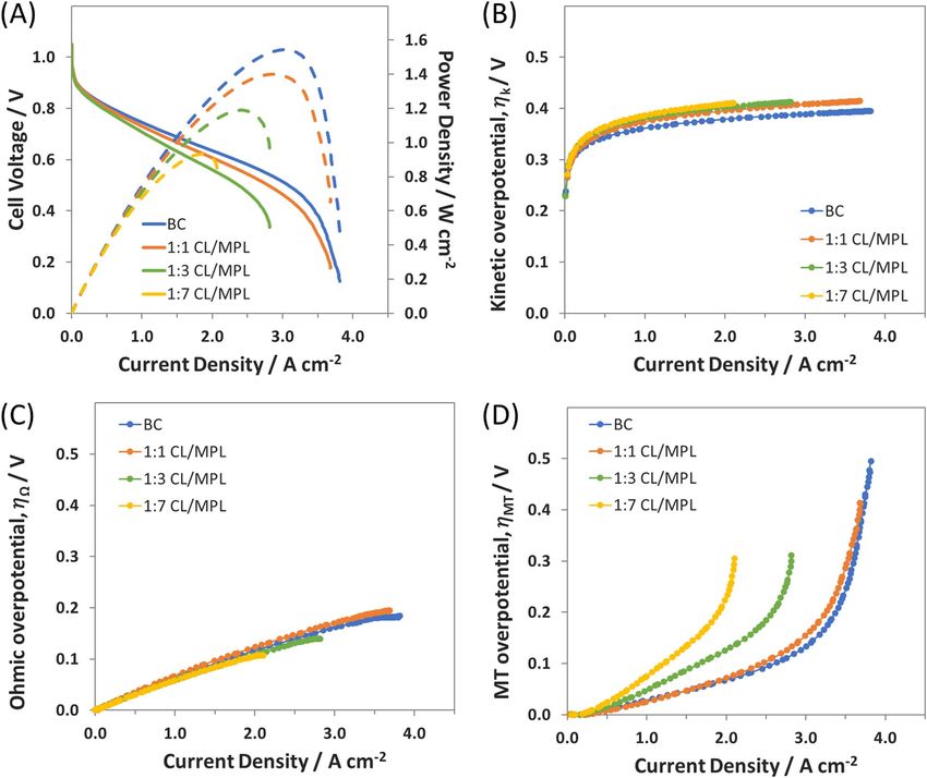
Figure 3. (A) i-V and i-P curves for all MPL based reduced anode loading cells compared with the full catalyst layer; (electrode and cell details in Table I);
Overpotentials for the i-V curves are deconvoluted into their (B) mass transfer (MT), (C) ohmic, and (D) kinetic contributions.
(while maintaining the total electrode thickness through the addition the excess water both accumulates in the CL and spills over into
of the MPL) impacts AEMFC fundamental behavior and performance. the MPL. When the catalyst layer is thinned, the MPL may also
To address this, electrodes were fabricated with much thinner cata- not be able to accept water quickly enough, resulting in increased
lyst layers, where the approximate CL:MPL thickness ratio was 1:3 flooding in the anode, and lower performance. It also is worth noting
(1:3CL/MPL) and 1:7 (1:7CL/MPL). here that the MPL is likely slightly more hydrophobic than the CL
During AEMFC testing, the 1:3 CL/MPL anode is able to retain ca. since it contains only carbon and ETFE powder – both intrinsically
80% of the achievable current (2.8 A cm−2 ) and peak power (1.2 W hydrophobic.
cm−2 ) of the BC anode, despite a 75% reduction in PGM loading With the above discussion in mind, it is then not too surprising that
on the anode (Figure 3A). This lends support to the idea that the further reducing the catalyst layer thickness in the 1:7 CL/MPL anode
majority of the active catalyst at high rates is located close to the led to even lower achievable current and peak power (Figure 3a). On
membrane, and that the necessary thickness and carbon content of the positive side, these losses are not linear and despite containing only
the electrode is tied to the handling of water. When the 1:3 CL/MPL 15% of the PGM catalyst of the BC anode, the 1:7 CL/MPL anode
polarization curve is deconvoluted, it can be seen that the kinetic and was able to achieve over 50% of the current density (2.2 A cm−2 ),
ohmic overpotentials (Figures 3C and 3D) are nearly identical to the and 60% of the peak power density (0.9 W cm−2 ). What this means
BC and 1:1 CL/MPL anodes, with the MT overpotential showing two is that there is a systematic gain in the mass activity of the catalyst in
changes. First, there was an increase in the initial MT overpotential the CL with decreasing CL:MPL ratio. This is shown in Table II and
slope, again indicative of the hydroxide transfer resistance. Second, the Figure 4A – where the mass specific power achievable by the anode is
mass transfer limiting current is reduced, a result that is not surprising increased from 2 W/mgPGM in the BC anode to 9 W/mgPGM in the 1:7
as the reactive volume of the electrode is thinner and closer to the CL/MPL anode. It should also be noted that the 1:7 CL/MPL had a
membrane. The membrane is responsible for removing a large portion PGM loading of only 0.11 mg cm−2 . These results show that, if paired
of the anode water through water uptake and back diffusion. However, with an appropriate PGM-free cathode, the anode reported here is
as the anode thins, the rate of water uptake is constant. Therefore, more than capable of meeting at least some of the US DOE Office ofF716 Journal of The Electrochemical Society, 165 (9) F710-F717 (2018)
Table II. Mass specific ECSA, current density in the kinetically controlled region, and mass specific power density of anode electrodes in the
manuscript.
1 1
Anode Type: BC 2 BC 2 D 1:1 CL/MPL 1:7 CL/MPL
ECSA, m2 g−1 51.5 46.5 48.3 25.7 30.4
I @ 0.90 V, mA cm−2 77 50 48 70 59
I @ 0.85 V, mA cm−2 265 154 157 240 190
PGM Specific Power, W/mgPGM 2.1 1.9 2.5 3.3 8.5
ROH -, m cm2 49.4 54.9 47.0 48.2 43.9
Energy Efficiency & Renewable Energy technical targets for polymer Interestingly, the CL/MPL electrodes show approximately half
electrolyte membrane fuel cells,30 most notably achieving a power the specific ECSA (m2 g−1 ) compared to the BC, 12 BC, and 12 D
density of 600 mW cm−2 with a total cell PGM loading of 0.125 mg electrodes. This really is unexpected since not only is the normalized
cm−2 . We believe that this is possible given the significant activity cell performance higher, but it was shown above that the catalyst
that currently surrounds non-PGM cathode catalysts in the literature. layer closest to the membrane is likely the most active. Therefore,
In fact, researchers have published AEMFCs with platinum free and it would be expected that the specific ECSA of the CL/MPL anodes
PGM free cathodes with significant performance, even surpassing would be comparable or higher than the BC anode, and certainly be
1 W cm−2 .20,31 That makes this work a significant contribution to higher than the 12 D anode. The expectation is strengthened by both
the AEMFC field, showing the promising future and viability of this the deconvoluted kinetic overpotential shown in Figure 3B, along
relatively immature cell variant. with the measured current density at 0.9 V and 0.85 V (Table II), a
Understanding the behavior of the 1:7 CL/MPL electrode CL wa- region of the polarization curve essentially under kinetic control.29 We
ter is important for the design of high performance, low PGM loading hypothesize that this result is the result of the hydrophobicity of the
electrodes for AEMFCs. As discussed above, if the MPL is unable MPL film. The effect of this hydrophobic layer is to reject water and
to accept water fast enough – which does appear to be the case here, prevent the gas streams from over hydrating the catalyst layer during
meaning that MPL design is a fruitful area for future work – due to operation. However, during the ECSA test, there is no liquid phase
its likely intrinsic hydrophobicity from the ETFE backbone, electrode water being produced by the cell, and the rejection of gas phase water
flooding is a concern. However, extending the reaction zone by em- by the MPL does not allow the CL to be properly hydrated during
ploying a more diluted strategy in the thin catalyst layer portion of the the ECSA experiment. Without proper hydration of the catalyst layer
electrode would be ill advised, as it was previously shown that the 12 there would be areas of the electrode that contain less water and hence
D diluted electrode performed relatively poorly compared to the more lower ionic conductivity and ECSA. Therefore, the ECSA measured
catalyst dense films. in the presence of this hydrophobic MPL is artificially low and likely
In addition to the mass activity, another important practical variable does not represent the true ECSA during cell operation. This suggests
that can aid with electrode design is the ECSA, which is a valuable that a new method may need to be developed to measure the ECSA
diagnostic in electrochemical systems – typically used to understand of these cells, and this will be investigated by our group in the future.
how effectively the electrode design has assembled the triple phase
boundary where the catalyst is ionically, electronically and reactively
available. Measuring the ECSA of platinum-based fuel cell electrode Conclusions
layers in operating fuel cells via CO stripping is a well-established In this work, the PGM loading of AEMFC anodes was drastically
technique that has been used for many years in PEMFCs, and has been reduced by replacing conventional single-layer electrodes with two-
extended to AEMFCs. Figure 4B shows the first (orange) and second layered anode electrodes. The two-layer electrodes had a thin catalyst
(blue) CVs for a typical CO-stripping experiment, and the results are layer in contact with the membrane and a microporous layer (con-
summarized in Table II. taining only the solid AEI powder and carbon) in contact with the
Figure 4. Mass specific diagnostic and performance of MPL modified anode electrodes; (A) PGM specific power and areal power density of CL/MPL anode
AEMFCs, (electrode and cell details in Table I); (B) Representative ECSA CO stripping CV of AEMFC (assembled with BC anode, full results detailed in Table II).Journal of The Electrochemical Society, 165 (9) F710-F717 (2018) F717
GDL. Some compositions were able to achieve peak power densities 6. L. Q. Wang, E. Magliocca, E. L. Cunningham, W. E. Mustain, S. D. Poynton,
as high as 1.4 W cm−2 – comparable to state-of-the-art AEMFCs R. Escudero-Cid, M. M. Nasef, J. Ponce-González, R. Bance-Souahli, R. C. T. Slade,
D. K. Whelligan, and J. R. Varcoe, Green Chem., 19, 831 (2017).
with high loading. Most importantly, application of the MPL at the 7. L. Wang, J. J. Brink, Y. Liu, A. M. Herring, J. Ponce-González, D. K. Whelligan, and
anode allowed the total PGM loading of that electrode to be reduced J. R. Varcoe, Energy Environ. Sci., 2154 (2017).
to 0.11 mg cm−2 while achieving a specific power of 8.5 W/mgPGM – a 8. J. Ponce-González, D. K. Whelligan, L. Wang, R. Bance-Soualhi, Y. Wang, Y. Peng,
performance that paired with a PGM-free cathode may be able to meet H. Peng, D. C. Apperley, H. N. Sarode, T. P. Pandey, A. G. Divekar, S. Seifert,
A. M. Herring, L. Zhuang, and J. R. Varcoe, Energy Environ. Sci., 9, 3724 (2016).
DOE targets. 9. A. M. Park, Z. R. Owczarczyk, L. E. Garner, A. C. Yang-Neyerlin, H. Long,
C. M. Antunes, M. R. Sturgeon, M. J. Lindell, S. J. Hamrock, M. Yandrasits, and
Acknowledgments B. S. Pivovar, ECS Trans., 80, 957 (2017).
10. R. Espiritu, M. Mamlouk, and K. Scott, Int. J. Hydrogen Energy, 41, 1120 (2016).
The authors gratefully acknowledge the financial support of the US 11. C. Chen, J. Pan, J. Han, Y. Wang, L. Zhu, M. A. Hickner, and L. Zhuang, J. Mater.
DOE Early Career Program Award Number DE-SC0010531 for the ef- Chem. A, 4, 4071 (2016).
fort expended by T.J.O., X.P., and W.E.M. to perform this work as well 12. D. R. Dekel, J. Power Sources, 375, 158 (2018).
13. B. S. Pivovar, DOE Hydrogen, and AMR Fuel Cells Program, (2017).
as equipment and supplies. Y.Z. acknowledges assistance from the 14. T. J. Omasta, L. Wang, X. Peng, C. A. Lewis, J. R. Varcoe, and W. E. Mustain, J.
“Graduate Student International Cultivation of Zhejiang University” Power Sources, 375, 205 (2018).
program. The diagnostic techniques and equipment at the National Re- 15. T. J. Omasta, A. M. Park, J. M. Lamanna, Y. Zhang, X. Peng, L. Wang,
newable Energy Laboratory was supported by the U. S. Department of D. L. Jacobson, J. R. Varcoe, D. S. Hussey, B. S. Pivovar, and W. E. Mustain, Energy
Environ. Sci., 11, 551 (2018).
Energy under Contract No. DE-AC36-08GO28308. The ETFE-based 16. I. Ledezma-Yanez, W. D. Z. Wallace, P. Sebastián-Pascual, V. Climent, J. M. Feliu,
materials used were developed and produced by the University Surrey and M. T. M. Koper, Nat. Energy, 2, 1 (2017).
team and this effort was funded by the UK’s Engineering and Physical 17. J. Durst, A. Siebel, C. Simon, F. Hasché, J. Herranz, and H. A. Gasteiger, Energy
Sciences Research Council (EPSRC grant EP/M014371/1). Environ. Sci., 7, 2255 (2014).
18. Z. Zhuang, S. A. Giles, J. Zheng, G. R. Jenness, S. Caratzoulas, D. G. Vlachos, and
Y. Yan, Nat. Commun., 7, 1 (2016).
ORCID 19. R. Gokhale, Y. Chen, A. Serov, K. Artyushkova, and P. Atanassov, Electrochem.
commun., 72, 140 (2016).
20. L. Wang, J. J. Brink, and J. R. Varcoe, Chem. Commun., 53, 11771 (2017).
Travis J. Omasta https://orcid.org/0000-0002-8002-6520 21. H. T. Chung, J. H. Won, and P. Zelenay, Nat. Commun., 4, 1922 (2013).
William E. Mustain https://orcid.org/0000-0001-7804-6410 22. M. Alesker, M. Page, M. Shviro, Y. Paska, G. Gershinsky, D. R. Dekel, and D. Zitoun,
J. Power Sources, 304, 332 (2016).
23. H. A. Miller, F. Vizza, M. Marelli, A. Zadick, L. Dubau, M. Chatenet, S. Geiger,
References S. Cherevko, H. Doan, R. K. Pavlicek, S. Mukerjee, and D. R. Dekel, Nano Energy,
33, 293 (2017).
1. J. R. Varcoe, P. Atanassov, D. R. Dekel, A. M. Herring, M. A. Hickner, P. A. Kohl, 24. S. Lu, J. Pan, A. Huang, L. Zhuang, and J. Lu, Proc. Natl. Acad. Sci., 105, 20611
A. R. Kucernak, W. E. Mustain, K. Nijmeijer, K. Scott, T. Xu, and L. Zhuang, Energy (2008).
Environ. Sci., 7, 3135 (2014). 25. S. Gu, W. Sheng, R. Cai, S. M. Alia, S. Song, K. O. Jensen, and Y. Yan, Chem.
2. B. P. Setzler, Z. Zhuang, J. A. Wittkopf, and Y. Yan, Nat. Nanotechnol., 11, 1020 Commun., 49, 131 (2013).
(2016). 26. Y. Wang, G. Wang, G. Li, B. Huang, J. Pan, Q. Liu, J. Han, L. Xiao, J. Lu, and
3. S. Gottesfeld, D. R. Dekel, M. Page, C. Bae, Y. Yan, P. Zelenay, and Y. S. Kim, J. L. Zhuang, Energy Environ. Sci., 8, 177 (2015).
Power Sources, 375, 170 (2018). 27. J. P. Kizewski, N. H. Mudri, and J. R. Varcoe, Radiat. Phys. Chem., 89, 64 (2013).
4. T. P. Pandey, A. M. Maes, H. N. Sarode, B. D. Peters, S. Lavina, K. Vezzù, 28. S. D. Poynton, R. C. T. Slade, T. J. Omasta, W. E. Mustain, R. Escudero-Cid, P. Ocón,
Y. Yang, S. D. Poynton, J. R. Varcoe, S. Seifert, M. W. Liberatore, V. Di Noto, and and J. R. Varcoe, J. Mater. Chem. A, 2, 5124 (2014).
A. M. Herring, Phys. Chem. Chem. Phys., 17, 4367 (2015). 29. H. A. Gasteiger, J. E. Panels, and S. G. Yan, J. Power Sources, 127, 162 (2004).
5. T. P. Pandey, H. N. Sarode, Y. Yang, Y. Yang, K. Vezzù, V. Di Noto, S. Seifert, 30. https://energy.gov/eere/fuelcells/doe-technical-targets-polymer-electrolyte-
D. M. Knauss, M. W. Liberatore, and A. M. Herring, J. Electrochem. Soc., 163, membrane-fuel-cell-components.
H513 (2016). 31. X. Peng, T. J. Omasta, J. M. Roller, and W. E. Mustain, Front. Energy, 14, 299 (2017).You can also read