Part 1.6: Performance Validation - Market Manual 1: Connecting to Ontario's Power System - Independent Electricity ...
←
→
Page content transcription
If your browser does not render page correctly, please read the page content below
PUBLIC IESO_REQ_0208

REQUIREMENTS
 Market Manual 1: Connecting to
 Ontario's Power System

 Part 1.6: Performance
 Validation

 Issue 14.0

 A document to mitigate risks that equipment will not
 be suitable for connection to the IESO-controlled
 grid and to clarify validation requirements.

 PUBLIC
Disclaimer
The posting of documents on this website is done for the convenience of market participants and other interested
visitors to the IESO website. Please be advised that, while the IESO attempts to have all posted documents conform
to the original, changes can result from the original, including changes resulting from the programs used to format
the documents for posting on the website as well as from the programs used by the viewer to download and read
the documents. The IESO makes no representation or warranty, express or implied that the documents on this
website are exact reproductions of the original documents listed. In addition, the documents and information
posted on this website are subject to change. The IESO may revise, withdraw or make final these materials at any
time at its sole discretion without further notice. It is solely your responsibility to ensure that you are using up-to-
date documents and information.
This market manual may contain a summary of a particular market rule. Where provided, the summary
has been used because of the length of the market rule itself. The reader should be aware however, that
where a market rule is applicable, the obligation that needs to be met is as stated in the market rules. To
the extent of any discrepancy or inconsistency between the provisions of a particular market rule and the
summary, the provision of the market rule shall govern.

Document ID IESO_REQ_0208
Document Name Part 1.6: Performance Validation
Issue Issue 14.0
Reason for Issue Issue released for Baseline 45.1
Effective Date June 2, 2021

Part 1.6: Performance Validation Document Change History

 Document Change History

 Issue Reason for Issue Date
 - For changes prior to 2016, refer to versions 9.0 and prior -
 5.0 Updated Section 3.2 Recognition of Inherent Limitation June 1, 2016
 with respect to primary frequency response requirements
 from wind generators.
 Added Figure 5 to illustrate the frequency response
 requirements from wind generators.
 Updated the List of Acceptable Compensator Dynamic
 Models in Section 5.7.
 Updated the List of Acceptable Wind Turbine and
 Photovoltaic Dynamic Models in Section 5.7 with the
 WECC second generation standard models.
 6.0 Added Section 2.5 Re-validation Testing and Reporting December 7, 2016
 Updated the List of Acceptable Compensator Dynamic
 Models in Section 5.7.
 7.0 Added GENTPJ to list of acceptable models. June 7, 2017
 Reference to PRC-019 and PRC-024 added in §5.
 Minor syntax improvements throughout the document.
 8.0 Section 5.7: Added DC4B to the list of Excitation System June 5, 2019
 Models.
 9.0 Section 5.5 Table 2- Updated: T’do from 2.0 to 6.0 for September 11, 2019
 both GENSAL and GENROU models.
 10.0 Section 5.7 Updated Wind Turbine and Photovoltaic October 4, 2019
 Acceptable Dynamic Model names to reflect PSSE and
 DSA nomenclature.
 Section 2.3 Updated to make distinction between a new
 installation and existing equipment swap between units.
 Added LST-48 to Related Documents Table.
 11.0 Issue released in advance of Baseline 44.0. June 29, 2020
 This market manual has been moved to the new Market
 Manual 1: Connecting to Ontario’s Power System
 series and the document part number has changed from
 2.20 to 1.6.
 12.0 Update the Market Manual to reflect the updates to December 2, 2020
 Market Rule Appendices 4.2 and 4.3. In addition, update
 the list of acceptable dynamic model to meet the NERC
 list.
 13.0 Issue released in advance of Baseline 45.0. Updated to February 26, 2021
 include electricity storage participation.
 14.0 Issue released for Baseline 45.1. Updated to include June 2, 2021
 generation unit and electricity storage unit information.

Issue 14.0 – June 2, 2021 Public
Part 1.6: Performance Validation Related Documents

 Related Documents
 Document ID Document Title
 MDP_PRO_0048 Market Manual 1.4: Connection Assessments
 PRO-408 Market Manual 1.5: Market Registration Procedures
 LST-48 Register Facility Help File

Issue 14.0 – June 2, 2021 Public
Part 1.6: Performance Validation Table of Contents

 Table of Contents
 Table of Contents ...................................................................................................... i

 List of Figures ......................................................................................................... iii

 List of Tables ........................................................................................................... iv

 Table of Changes ..................................................................................................... v

 Market Manual .......................................................................................................... 1
 Market Procedures ......................................................................................................... 1

 1. Purpose ............................................................................................................. 2
 1.1 Purpose............................................................................................................... 2
 1.2 Scope.................................................................................................................. 2
 1.3 Who Should Use This Manual ............................................................................ 3
 1.4 Conventions ........................................................................................................ 3

 2. General Requirements ..................................................................................... 4
 2.1 Managing Changes to Performance Standards .................................................. 4
 2.2 Meet Prevailing or Maintain Existing................................................................... 5
 2.3 Outage Slip or Connection Assessment ............................................................. 6
 2.4 Demonstrating Performance ............................................................................... 6
 2.5 Re-validation Testing and Reporting................................................................... 7
 2.6 Equivalent Machine............................................................................................. 7
 2.7 Dynamic Disturbance Recorder (DDR) ............................................................... 7

 3. Requirements for Generation and Electricity Storage Facilities .................. 9
 3.1 Off-Nominal Frequency Operation ...................................................................... 9
 3.2 Speed/Frequency Regulation ........................................................................... 10
 3.3 Ride Through .................................................................................................... 14
 3.4 Active Power ..................................................................................................... 19
 3.5 Reactive Power................................................................................................. 21

Issue 14.0 – June 2, 2021 Public i
Part 1.6: Performance Validation Table of Contents

 3.6 Automatic Voltage Regulator (AVR) ................................................................. 23
 3.7 Excitation System ............................................................................................. 25
 3.8 Power System Stabilizer (PSS) ........................................................................ 26
 3.9 Phase Unbalance.............................................................................................. 27
 3.10 Armature and Field Limiters.............................................................................. 28
 3.11 Technical Characteristics.................................................................................. 30
 3.12 Reactive Power Response for Inverter-Based Units......................................... 30
 3.13 Electricity Storage ............................................................................................. 31

 4. Validation of Other Elements......................................................................... 32
 4.1 General ............................................................................................................. 32
 4.2 Switches and Breakers ..................................................................................... 32
 4.3 Transmission Circuits........................................................................................ 32
 4.4 Series Compensation........................................................................................ 32
 4.5 Shunt Compensation ........................................................................................ 33
 4.6 Transformers..................................................................................................... 33
 4.7 Synchronous Condensers and Static var Compensators (SVC) ...................... 33
 4.8 Protection Systems ........................................................................................... 33
 4.9 Special Protection Systems (SPS).................................................................... 33

 5. Testing, Reporting, and Modelling ................................................................ 39
 5.1 Conventional Generation and Non-Inverter Based Electricity Storage
 Facilities Reporting Requirements .................................................................... 39
 5.2 Non-Conventional Generation and Inverter-Based Electricity Storage
 Facilities Reporting Requirements .................................................................... 41
 5.3 Summary of Generation and Electricity Storage Facilities Considerations and
 Tests ................................................................................................................. 43
 5.4 Summary of Other Equipment Considerations and Tests................................. 44
 5.5 Default Modelling .............................................................................................. 45
 5.6 Acceptable Dynamic Models............................................................................. 46
 5.7 Abbreviations and Acronyms ............................................................................ 49

Issue 14.0 – June 2, 2021 Public ii
Part 1.6: Performance Validation List of Figures

 List of Figures
 Figure 1 - Equipment Performance Requirement Evolution .........................................................4
 Figure 2 - Dynamic Disturbance Recorder Inputs .........................................................................8
 Figure 3 - Off-Nominal Frequency No-Trip Requirement ..............................................................9
 Figure 4 - Active Power Speed and Magnitude of Response Requirement................................11
 Figure 5 - Primary Frequency Response Requirement ..............................................................13
 Figure 6 – NERC PRC-024 Voltage Ride Through Requirement ...............................................16
 Figure 7 - Single-Line Diagram of No-Tripping for Out-of-Zone Faults Requirement .................17
 Figure 8 - Example Current Waveform for Showing Fault Clearing Times .................................18
 Figure 9 - Positive Sequence Voltage During a Fault .................................................................18
 Figure 10 - Reactive Power Requirement at all Levels of Active Power .....................................20
 Figure 11 - Reactive Power Priority ............................................................................................20
 Figure 12 - Fixed Admittance Capacitors Compensating Losses Within Generation Facilities ..21
 Figure 13 - Regulation with Individual Units at Limit ...................................................................22
 Figure 14 - Voltage Control Point................................................................................................23
 Figure 15 - Example of Configuration Which Requires Two AVR Voltage Sources ...................24
 Figure 16 - Excitation System Ceiling Requirements..................................................................25
 Figure 17 - Power System Stabilizer Phase Compensation Margin ...........................................26
 Figure 18 - Temporary Field Current Requirements ...................................................................28
 Figure 19 - Capability Curve .......................................................................................................29
 Figure 20 – Acceptable vs unacceptable reactive power response of Inverter-based units .......31
 Figure 21 - Contingency Detection Logic....................................................................................34
 Figure 22 - Breaker Trip Module .................................................................................................35
 Figure 23 - Generation Rejection................................................................................................36
 Figure 24 - Generation Runback.................................................................................................37
 Figure 25 - Protection Timing......................................................................................................38
 Figure 26 - Active Power Participation Justified by Performance ...............................................42

Issue 14.0 – June 2, 2021 Public iii
Part 1.6: Performance Validation List of Tables

 List of Tables
 Table 1 - Default Power Flow and Dynamics Parameters ..........................................................45
 Table 2 - Default Machine Parameters .......................................................................................45
 Table 3 - Default AVR/Exciter Parameters .................................................................................45
 Table 4 - Default PSS Parameters..............................................................................................45

Issue 14.0 – June 2, 2021 Public iv
Part 1.6: Performance Validation Table of Changes

 Table of Changes
 Reference Description of Change
 (Section and
 Paragraph)

 Section 3.3 Updated section 3.3 information to include clarifications on applicability of
 requirements in Category 12 of Appendix 4.3 of Chapter 4 of the market rules to
 generation units and electricity storage units connected within a connected
 wholesale customer’s or distributor’s facilities or distribution system.

Issue 14.0 – June 2, 2021 Public v
Part 1.6: Performance Validation Market Manual

 Market Manual
 The Market Manuals consolidate the market procedures and associated forms, standards and policies
 that define the operation of the various areas within the IESO-administered markets. Market
 procedures provide more detailed descriptions of the requirements for various activities than are
 specified in the Market Rules. Where there is a discrepancy between the requirements in a document
 within a Market Manual and the Market Rules, the Market Rules shall prevail. Standards and policies
 appended to, or referenced in, these procedures provide a supporting framework.

 Market Procedures
 “Connecting to Ontario's Power System” is Series 1 of the Market Manuals, where this document
 forms Part 1.6: Performance Validation.

 - End of Section -

Issue 14.0 – June 2, 2021 Public 1
Part 1.6: Performance Validation 1. Purpose

 1. Purpose
 The primary object of the Performance Validation manual is to mitigate risks that equipment will not
 be suitable for connection to the IESO-controlled grid. A secondary object is to clarify the scope and
 nature of activities that shall be performed by Market Participants to balance a conditional right to
 connect to the IESO-controlled grid granted at the end of the connection assessment process with an
 obligation to demonstrate equipment performance required during the market entry process. IESO
 requires an acceptable level of confidence that models for power system equipment are suitable for its
 planning and operating decisions. Performance validation achieves this level of confidence.

 1.1 Purpose
 Market Manual 1.6: Performance Validation is the third of three market manuals that cover the
 Connecting to Ontario’s Power System process. The Connecting to Ontario’s Power System process
 consists of six (6) stages, which are described in the following market manuals:

 Stage Market Manual

 1. Prepare application Part 1.4: Connection Assessment and Approval
 2. Obtain conditional approval to (formerly Market Manual 2.10)
 connect
 3. Design and build N/A 1
 4. Authorize market and program Part 1.5: Market Registration Procedures
 participation
 5. Register equipment
 6. Commission equipment and validate Part 1.5: Market Registration Procedures, and
 performance Part 1.6: Performance Validation
 (formerly Market Manual 2.20)

 This market manual contains the procedures related to performance validation, which encompasses
 Stages 6 of the process, and is a guide to mitigate risks that equipment will not be suitable for
 connection to the IESO-controlled grid and to clarify validation requirements.

 1.2 Scope
 This Performance Validation manual describes how equipment will be treated as performance
 standards evolve, when performance validation is required, what an acceptable validation comprises,
 and other topics related to equipment performance.

 1
 The “Stage 3: Design and build” activities are determined between the connection applicant and its associated
 transmitter or distributor after the completion of Stages 1 and 2.

Issue 14.0 – June 2, 2021 Public 2
Part 1.6: Performance Validation 1. Purpose

 This Performance Validation manual describes performance requirements and validation procedures
 for common components of the IESO-controlled grid with more attention devoted to generating units
 and electricity storage units. Modelling, testing, and reporting considerations are presented in
 Section 5.

 1.3 Who Should Use This Manual
 The Performance Validation manual is for external use by those contemplating connections to the
 IESO-controlled grid (ICG) and for internal use by IESO staff.

 1.4 Conventions
 The standard conventions followed for market manuals are as follows:

 • The word ‘shall’ denotes a mandatory requirement;
 • Terms and acronyms used in this market manual including all parts thereto that are italicized
 have the meanings ascribed thereto in Chapter 11 of the “Market Rules”; and
 • Double quotation marks are used to indicate titles of legislation, publications, forms, and
 other documents.
 Any procedure-specific convention(s) shall be identified within the procedure document itself.

 - End of Section -

Issue 14.0 – June 2, 2021 Public 3
Part 1.6: Performance Validation 2. General Requirements

 2. General Requirements

 2.1 Managing Changes to Performance Standards
 In general, new equipment or major changes to existing equipment must meet prevailing requirements
 while maintenance and minor changes must preserve existing capability.
 As it is impracticable to change equipment each time “Market Rules” equipment performance
 requirements are updated, an orderly process to evolve equipment performance is necessary.
 Persistent performance changes after market entry are anticipated only in association with a new
 connection assessment. These concepts are illustrated below.

 Unchanged
 equipment
 A connection assessment is required for preserves
 Evolving performance requirement modified equipment. Major modifications capability at
 Appendix 4.2 Requirement

 must satisfy prevailing requirements. market
 opening

 New equipment must satisfy prevailing
 requirements when assessed
 Market Opens

 Time

 Equipment subject to Appendix 4.2 Connection Assessment

 Figure 1 - Equipment Performance Requirement Evolution

 To assist compliance verification, IESO will document the prevailing performance requirements at the
 time of equipment connection.

Issue 14.0 – June 2, 2021 Public 4
Part 1.6: Performance Validation 2. General Requirements

 2.2 Meet Prevailing or Maintain Existing
 A ‘major’ change must meet prevailing “Market Rule” requirements. Other changes, such as using
 like-for-like spares for unplanned equipment failures, must at a minimum maintain existing
 performance previously approved for connection. The IESO should be consulted when in doubt if a
 change is ‘major’.
 A ‘major’ change is a planned replacement or modification of the output stage of an associated
 system. For guidance, replacing example minor system components in the table below would not
 trigger an obligation to meet prevailing requirements while replacing example major system
 components are ‘major’ changes that would trigger this obligation.

 System Rotating Static Exciter Governor Inverter- Based
 Exciter Resources
 (Including DERs)

 Minor AVR AVR or PSS or both Speed Regulator Plant Controller
 System
 Components

 Pilot Exciter or Bridge or Exc.
 Amplidyne Transformer

 Major Main Exciter Bridge and Exc. Turbine-control Main Inverter
 System Transformer mechanism
 Components

 Replacing the AVR or pilot exciter or both in a rotating system would not trigger a need to meet the
 prevailing requirements as neither of these are major components. Replacing the main exciter in a
 brushless system would not trigger the need to meet the prevailing requirements unless the main
 generator field connections were accessible. For units with accessible slip rings, changing the main
 exciter would trigger a need to meet prevailing standards. For static systems, changing both the
 excitation transformer and the bridge would trigger an obligation to meet prevailing standards, but
 changing either the excitation transformer or the bridge would not trigger this obligation.
 It is not acceptable to split the replacement of a major component into a series of minor component
 replacements to escape performance requirements in the prevailing standard. The provision to allow
 for the replacements with spares is not intended to allow some equipment to perpetually remain below
 a higher prevailing performance standard. When an asset owner decides equipment has reached the
 end of its normal design life, replacements must satisfy prevailing performance standards.
 Non-major replacements should not inhibit the capability to satisfy a prevailing standard to the extent
 practicable. For example, a replacement excitation system transformer should be not only able to
 function with the existing bridge but also not preclude meeting prevailing requirements (e.g. required
 positive and negative ceiling voltages) when the bridge is replaced if this transformer will be retained.
 Performance from an existing spare must maintain existing capability. A spare must satisfy
 prevailing requirements at the time of its purchase. For example, replacing a failed dc exciter with an
 existing spare is acceptable provided other parameters are unaltered (e.g. AVR settings). In cases of

Issue 14.0 – June 2, 2021 Public 5
Part 1.6: Performance Validation 2. General Requirements

 like-for-like replacements, testing can be limited in scope (e.g. open circuit tests, steady state field
 current measurements, etc.) to confirm there will be no material changes in performance.

 2.3 Outage Slip or Connection Assessment
 Maintenance work and short duration de-ratings fall under the regime of the IESO outage
 management process not the connection assessment process.
 New or modified equipment must pass through both the IESO connection assessment and market
 entry processes before connection to the IESO-controlled grid. With ‘maintenance’ work there is no
 reasonable expectation of change to performance characteristics reported to the IESO. Activities at
 either end of the spectrum are easy to categorize. Replacing a wiped bearing requires an outage slip
 while installing a new exciter requires a connection assessment. Swapping existing like-for-like
 exciters between units requires an outage slip and tests that confirm to the IESO that performance
 characteristics are unchanged. When there is a reasonable expectation that performance
 characteristics reported to the IESO have changed, then an application to the IESO connection
 assessment process is required. Like-for-like applications are streamed into an expedited process for
 improved efficiency.

 2.4 Demonstrating Performance
 Verified equipment performance characteristics are often not available until after a connection
 assessment application is submitted to the IESO. Delays may arise when measured performance is
 less than predicted in the connection assessment process as re-assessments take time. Often it may be
 more efficient to begin by assuming default characteristics that marginally satisfy performance
 requirements. If IESO studies show this performance is good enough, then no further action is
 required by the proponent related to modelling during the Connection Assessment process. When this
 approach would lead to connections restrictions; a proponent should be consulted to determine the
 most practicable path forward. Default characteristics are presented in Section 5.5.
 Performance that cannot be validated by a proponent during the Market Entry process will not be
 assumed to meet requirements for connection. Equipment often must be connected to the ICG to
 complete performance validation. Equipment will not be connected until IESO accepts the scope of
 validation testing and permission to remain connected depends on successful demonstration of
 required performance. Testing will be completed within two months of connection.
 An acceptable validation will generally comprise measurements that closely match simulation
 predictions using the models provided. Measured outcomes and simulation results are required to be
 expressed in a manner that facilitates comparison by overlying simulations results with measured
 outcomes for a given test. In some cases, (e.g. underfrequency trip settings) it will be sufficient to
 report a setting and demonstrate that it satisfies the requirement. Testing to demonstrate reliable
 performance should be as realistic as reasonably achievable. For example, manually changing from
 “AUTO” to “MANUAL” is not as good a bumpless transfer test as pulling the PT fuse as the former
 is not a true end-to-end test. Testing conditions must be tailored to mitigate adverse effects of
 unexpected or substandard performance.
 The Market Participant is responsible for making provisions to test equipment in a safe and
 controlled manner. For example, setpoint changes are often ramped rather than stepped during usual

Issue 14.0 – June 2, 2021 Public 6
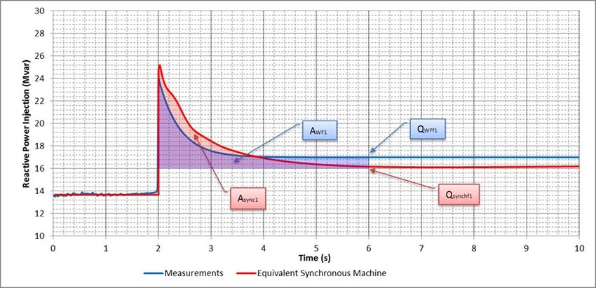
Part 1.6: Performance Validation 2. General Requirements

 operation. Ramping can interfere with conclusively demonstrating dynamics requirements have been
 satisfied. If a step change is necessary to demonstrate performance, the Market Participant will be
 responsible for enabling this step change.
 Simulation results from detailed models cannot be put forward as validation of models provided for
 IESO studies. Measurements are required by IESO to validate performance.
 Type tests performed in accordance with recognized standards may reduce the scope of validation
 testing. Type tests are especially useful for validating parameters that represent inherent
 characteristics (e.g. inertia) or properties onerous to test (e.g. ride-through). Some care should be
 taken to avoid confusing vendor acceptance tests with type tests. Type tests are performed by an
 accredited and independent testing agency to widely accepted industry standards.
 It may be impracticable to guarantee that all elements of a facility, especially those elements not
 subject to modification, satisfy all IESO performance requirements. It is sufficient for a Market
 Participant to confirm there are no known performance issues and to commit to resolving
 performance issues as they become known.

 2.5 Re-validation Testing and Reporting
 Steady state and dynamic capability of generating units, electricity storage units, synchronous
 condensers, STATCOMS, and SVCS must be validated on a periodic basis or following
 modifications that affect capability. The IESO will use NERC MOD standards (MOD-025, MOD-
 026, and MOD-027) requirements as a guide to identify performance requirements. Steady state
 capability must be re-validated at least every five years. Dynamic capability must be re-validated at
 least every ten years.
 IESO shall post details concerning re-validation testing and reporting on its public website.

 2.6 Equivalent Machine
 The “Market Rules” tendency to express performance requirements at a transmission connection
 point is intended to cater for all types of generation and electricity storage technologies. Many
 aspects of conventional units are either not present or present in a very different form in non-
 conventional facilities. For example, a 100 MVA hydro-electric unit will have a single terminal
 where voltage is regulated while a 100 MVA wind generation facility will have many unit terminals
 and none of these terminals may be a suitable voltage regulation point.
 Voltage, active power, and reactive power performance at the connection point for non-conventional
 technologies is required to be consistent with that of an equivalent synchronous machine with
 characteristic parameters within typical ranges. In the example above, the multiple-unit wind
 generation facility will be expected to provide the same voltage support at the connection point as the
 single-unit hydro-electric generation facility.

 2.7 Dynamic Disturbance Recorder (DDR)
 A permanent dynamic disturbance recorder must be installed to provide the capability to demonstrate
 equipment continues to meet dynamic performance requirements during and after commissioning

Issue 14.0 – June 2, 2021 Public 7
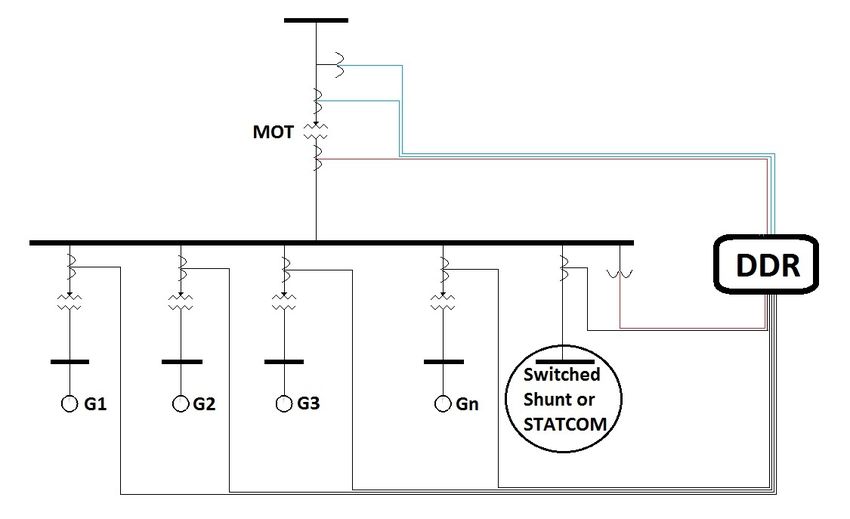
Part 1.6: Performance Validation 2. General Requirements

 tests. Measurements must be synchronized to within 2 milliseconds or less of Universal Coordinated
 Time scale (UTC). Sampling rates, triggering methods, monitoring selections and reporting format
 (e.g. COMTRADE) must be accepted by the IESO prior to its authorization to energize the main
 output transformer.
 The figure below illustrates the primary voltage and current locations for inputs to the DDR must not
 be separated by material impedance. In this figure, blues lines correspond to a set of CT and PT
 inputs on the high voltage side of the main output transformer and re d lines on the low voltage side.
 Additional inputs, as shown by grey lines, can be useful to identify the source of performance
 problems.
 The DDR must be capable of recording two sets of channels with the following sampling rates:
 1) High speed channels with a capability to store at least 1 second of instantaneous values of the
 three phase voltages and currents at a minimum sampling rate of 100 samples per cycle.
 2) Low speed channels with the capability to store at least 30 seconds of frequency, positive
 sequence voltage, positive sequence current, 3-phase active power, and 3-phase reactive
 power at a minimum sampling rate of 1 sample per cycle.
 The DDR triggering methods are location sensitive and hence they will be communicated on a
 project-by-project basis during the IESO’s market entry process. Typical triggers are low frequency,
 low positive sequence voltage and high rate of change of active and reactive power. High/low speed
 channels are typically configured to record 200 ms/5 s before a triggering event. DDR records must
 be available upon IESO request.
 One example of a dynamic disturbance recorder that meets all IESO requirements is the Tesla 4000
 by ERL Phase.

 Figure 2 - Dynamic Disturbance Recorder Inputs

 - End of Section -

Issue 14.0 – June 2, 2021 Public 8
Part 1.6: Performance Validation 3. Requirements for Generation and Electricity Storage Facilities

 3. Requirements for Generation and
 Electricity Storage Facilities
 The next subsections discuss each technical requirement for generation facilities and electricity
 storage facilities to mitigate the risk that equipment will not be suitable for connection. The Table in
 Section 5.3 summarizes anticipated tests. Generation models acceptable to IESO are listed in Section
 5.6.

 3.1 Off-Nominal Frequency Operation
 1. Off-Nominal Operate continuously between 59.4 Hz and 60.6 Hz and for a limited period of time in the region bounded by
 Frequency straight lines on a log-linear scale defined by the points (0.0 s, 57.0 Hz), (3.3 s, 57.0 Hz), and (300 s, 59.0 Hz)
 Operation and the straight lines on the log-linear scale defined by the points (0.0 s, 61.8 Hz), (8 s, 61.8 Hz), and (600 s,
 60.6 Hz).

 This is a requirement not to trip within a defined frequency-time area and it should not be
 misinterpreted as a requirement to trip outside of this region. IESO does not have either an
 underfrequency trip or overfrequency trip requirement and it discourages unnecessary or premature
 equipment tripping for any reason. As shown in Figure 3, the area outside of the frequency ride-
 through “No Trip” zones should not be interpreted as a “Must Trip” zone, and should be considered
 as a “May Trip” zone. Tripping should be based on physical equipment limitations or specifications.
 Protection functions should be set as wide as possible while ensuring equipment safety and reliability.

 63

 May Trip Zone
 62

 No Trip Zone
 61

 Continuous Operation
 60
 Frequency (Hz)

 59

 No Trip Zone

 58

 57
 May Trip Zone

 56
 -1 0 1 2 3
 10 10 10 10 10

 Time (Seconds)

 Figure 3 - Off-Nominal Frequency No-Trip Requirement

 Essential auxiliary functions also must not trip within this frequency-time region. Generators and
 electricity storage participants have discretion to select the number of frequency-time pairs to define
 a tripping requirement but no pair can be within the forbidden region. Generation units and electricity

Issue 14.0 – June 2, 2021 Public 9
Part 1.6: Performance Validation 3. Requirements for Generation and Electricity Storage Facilities

 storage units can be manually disconnected after consultation with the IESO operators if the
 frequency does not recover above 59.4 Hz after 300 seconds.
 Tripping based on instantaneous frequency calculations is not permitted. Inverter-based generation
 and electricity storage units shall calculate the fundamental frequency over a time window of 3 to 6
 cycles and filter for spikes caused by phase jumps due to disturbances and routine switching events.

 3.2 Speed/Frequency Regulation
 2. Speed/Frequency Regulate speed/frequency with an average droop based on maximum active power adjustable between 3% and
 Regulation 7% and set at 4% unless otherwise specified by the IESO. Regulation deadband shall not be wider than
 ±0.06%. Speed/frequency shall be controlled in a stable fashion in both interconnected and island operation. A
 sustained 9% change of applicable rated active power as defined in category 4 after 10 s in response to a step
 change of speed of 0.5% during interconnected operation shall be achievable. Due consideration will be given
 to inherent limitations such as mill points and gate limits when evaluating active power changes. Control
 systems that inhibit primary frequency response shall not be enabled without IESO approval.

 Droop
 Droop will be calculated on a generation facility or electricity storage facility basis. For a combined-
 cycle facility, the droop for the gas units will be required to compensate to the extent practicable for
 steam units. Reducing unit droop below 3% to achieve an overall facility droop of 4% will not be
 required by IESO.
 Some types of generation (e.g. hydro-electric) may require different governor control settings to
 achieve both a rapid response during interconnected operation and a stable response during island
 operation. The switch between these two settings must be automatically triggered by conditions that
 are subject to IESO approval. Normally either frequency alone or a combination of frequency and
 rate of change of frequency would be an acceptable trigger to switch to island settings. Where a
 recognized contingency would establish an island, this automatic switch should take place for
 frequency deviations larger than required to initiate the first step of automatic underfrequency load
 shedding (i.e. 59.3 Hz). Where an extreme contingency would be required to establish an island, this
 automatic switch should take place for frequency deviations larger than the frequency declines (i.e.
 58.0 Hz) the automatic underfrequency load shedding program is intended to limit.
 Electricity storage units shall provide frequency regulation according to its droop and deadband
 settings at all active power levels including when it is withdrawing active power.

Issue 14.0 – June 2, 2021 Public 10
Part 1.6: Performance Validation 3. Requirements for Generation and Electricity Storage Facilities

 Speed and Magnitude of Response
 The required relationship among time, speed (frequency), and active power are sketched below.

 100%
 Speed

 99.5%

 The immediate and
 sustained plantresponse ΔPsustained
 ΔPimmediate must be larger than 9% of
 Response (MW) rated active power
 10 s 30 min

 100.5%
 Speed

 100%

 The immediate and
 sustained plant response ΔPsustained
 ΔPimmediate
 must be larger than 9% of
 Response (MW)
 rated active power

 10 s 30 min

 Figure 4 - Active Power Speed and Magnitude of Response Requirement

Issue 14.0 – June 2, 2021 Public 11
Part 1.6: Performance Validation 3. Requirements for Generation and Electricity Storage Facilities

 Recognition of Inherent Limitations
 Units at full power will not be expected to contribute more active power when frequency declines nor
 will units at minimum power be expected to contribute less active power when frequency increases.
 When a performance feature is commercially available from a variety of vendors, then it ceases to be
 an inherent limitation.
 As several vendors now offer the capability to use energy stored in rotating wind turbine blades to
 provide a temporary boost in active power; this feature is now required to help mitigate severe
 frequency declines. However, no capability for a sustained increase in active power for frequency
 declines is required from wind turbines so there is no need to continually “spill” wind.
 The IESO will notify generators that have wind turbines with this capability when this feature must be
 placed in-service.
 Functional requirements for this feature are as follows:
 - The active power boost shall be triggered when frequency drops below 59.7 Hz.
 - The boost activation time shall not exceed 1 second.
 - The boost must exceed 10% of pre-trigger active power.
 - The boost shall last at least 10 seconds if frequency remains under 59.964 Hz.
 - The boost shall be cancelled if frequency rises above 59.964 Hz.
 - The rate of energy withdrawn from the system during active power recovery must in general
 be less than the rate of energy injected into the system during the active power boost.
 - Following activation, the boost capability shall be available again within 30 minutes.
 Representative responses of a wind turbine with this feature placed in-service, consistent with the
 functional requirements above, are shown in Figure 5 below for two illustrative cases (corresponding
 to two different triggering events).
 Solar generation does not now have a similar store of energy so active power increases are not yet
 required from solar installations, but this may change as technology evolves.
 All generation types (e.g. conventional, wind, solar) must reduce active power for overfrequency
 excursions outside of the ±0.06% (i.e. 36 mHz) deadband.

Issue 14.0 – June 2, 2021 Public 12
Part 1.6: Performance Validation 3. Requirements for Generation and Electricity Storage Facilities

 Control Systems that Inhibit Primary Frequency Response
 Control systems that inhibit primary frequency response shall be supported by a rationale that
 demonstrates performance reductions are offset by other advantages. For example, a slow outer loop
 control of small hydro-electric units to maximize efficiency would be permitted if interference is
 slight with active power response within 30 seconds following an upset. In this case, an immaterial
 reduction in performance to maintain reliability is offset by a greater public good.

 Figure 5 - Primary Frequency Response Requirement

Issue 14.0 – June 2, 2021 Public 13
Part 1.6: Performance Validation 3. Requirements for Generation and Electricity Storage Facilities

 3.3 Ride Through
 3. Voltage Ride- Ride through routine switching events and design criteria contingencies assuming standard fault detection, auxiliary
 Through relaying, communication, and rated breaker interrupting times unless disconnected by configuration. For Inverter-based
 units, momentary current cessation or reduction of output current during system disturbances is not permitted without
 IESO approval.

 Equipment must not trip for spikes associated with routine high voltage capacitor switching,
 automatic reclosure, or for design criteria contingencies that do not disconnect generation facilities or
 electricity storage facilities by configuration. Lightning strikes on the IESO-controlled grid also
 must not result in generation or electricity storage unit trips unless disconnected by configuration.
 Minor internal upsets must also not result in equipment tripping. For example, the loss of the voltage
 signal following a blown PT fuse should result in a bumpless transfer to manual control rather than a
 trip.
 Large shunt reactive elements are common at transmission stations in Ontario and the switching of
 these shunts must not result in equipment trips. Shunt reactors range in size up to 150 Mvar while
 shunt capacitor banks range in size up to 400 Mvar. The magnitude of routine switching transients is
 site dependent and must be considered in the facility design.
 Both low and high voltage aspects of ride through will be exercised by contingencies. Tripping is not
 permitted either for the low voltage before fault clearing or for the high voltage spike after fault
 clearing. Generation facilities and electricity storage facilities must have sufficient high and low
 voltage ride through capability to not trip needlessly. At a minimum, generators and electricity
 storage participants must follow the ride through requirements identified in the reliability standards;
 i.e., NERC PRC-024 for transmission connected generation units and CSA C22.3 no. 9 (or UL1741
 SA or equivalent standards but only as an interim certification until equipment compliant with C22.3
 no. 9 becomes available in Ontario) for units connected within a distribution system or a wholesale
 customer. As an example, NERC PRC-024-2 ride through requirements diagram is shown below.
 More stringent requirements may be identified in the system impact assessment as a result of IESO
 system studies.
 Generation units connected within a connected wholesale customer’s or distributor’s facilities or
 distribution systems, that were issued a connection impact assessment from the local distribution
 company (“LDC”) before September 21, 2020 remain subject to the connection requirements under
 Category 12 of Appendix 4.3 of Chapter 4 of the market rules that were in place as of the date of such
 issuance. Generation units connected within a connected wholesale customer’s or distributor’s
 facilities or distribution systems that were issued a connection impact assessment from the LDC on or
 after September 21, 2020 are subject to the requirements in Category 12 of Appendix 4.3 that came
 into effect on such date.
 Electricity storage units connected within a connected wholesale customer’s or distributor’s facilities
 or distribution systems, that were issued a connection impact assessment from the LDC before
 January 18, 2021 remain subject to the connection requirements in place under Category 12 of
 Appendix 4.3 as of the date of such issuance. Electricity storage units connected within a connected
 wholesale customer’s or distributor’s facilities or distribution systems that were issued a connection
 impact assessment from the LDC on or after January 18, 2021 are subject to the requirements in
 Category 12 of Appendix 4.3 that came into effect on such date.

Issue 14.0 – June 2, 2021 Public 14
Part 1.6: Performance Validation 3. Requirements for Generation and Electricity Storage Facilities

 For clarity:
 1. The requirements in Category 12 of Appendix 4.3 as described in the two preceding
 paragraphs also apply to generation units or electricity storage units connected behind a
 distribution electricity meter.

 2. For generation units or electricity storage units connected within a connected wholesale
 customer’s or distributor’s facilities or distribution systems and for which a Micro-
 Embedded Generation Facility Connection Agreement published by the OEB is entered,
 the requirements in the Micro-Embedded Generation Facility Connection Agreement at
 the time the connection impact assessment from the LDC was issued apply in place and
 instead of the requirements set out in Category 12 of Appendix 4.3.

 3. Inverter-based generation units or electricity storage units connected within a connected
 wholesale customer’s or distributor’s facilities or distribution systems are permitted to have
 enabled momentary current cessation or reduction of output current as permitted under CSA
 C22.3 no. 9 (or, alternatively, as permitted under UL1741 SA or equivalent standards, but
 only as an interim certification until equipment compliant with C22.3 no. 9 becomes available
 in Ontario).

 4. The requirements in Category 12 of Appendix 4.3 are deemed met if the generation units or
 electricity storage units connected within a connected wholesale customer’s or distributor’s
 facilities or distribution systems are compliant with CSA C22.3 no. 9 (or, alternatively,
 UL1741 SA or equivalent standards, but only as an interim certification until equipment
 compliant with C22.3 no. 9 becomes available in Ontario). The minimum ride-through
 settings are provided in Tables 12 and 14 of the CSA C22.3 no.9 standard.

Issue 14.0 – June 2, 2021 Public 15
Part 1.6: Performance Validation 3. Requirements for Generation and Electricity Storage Facilities

 Figure 6 – NERC PRC-024 Voltage Ride Through Requirement

 Inverter-based generation and electricity storage units shall not reduce current injection at the high –
 voltage terminal of the main output transformer during routine switching events and design criteria
 contingencies. Inverter-based generation units and electricity storage units shall control the type of
 current needed based on terminal conditions, and respond accordingly to provide a combination of
 active and reactive current injection (e.g., reactive power priority).

 Tripping for contingencies that would disconnect by configuration is permitted. A need to clear faults
 without intentional delay shall prevail in cases of conflict between a need to clear in-zone faults
 without intentional delay and a need to ride through out-of-zone faults.

Issue 14.0 – June 2, 2021 Public 16
Part 1.6: Performance Validation 3. Requirements for Generation and Electricity Storage Facilities

 Tripping for routine shunt or line switching
 and out-of-zone faults is not permitted.

 Tripping for contingencies
 that disconnect by
 configuration is permitted

 Figure 7 - Single-Line Diagram of No-Tripping for Out-of-Zone Faults Requirement

 The standard times below should be used in lieu of site-specific timing.
 Voltage Local Normal Local Remote Remote Delayed Breaker Interrupting Breaker Failure
 Level Clearing Time Delayed Normal Clearing Time Times (ms & cycles) 62b Time
 (kV) (ms) Clearing Time Clearing Time
 (ms) (ms) (ms) (ms)

 500 66 156 91 181 33 (2) 90

 230 83 192 108 217 50 (3) 105

 115 116 256 141 281 83 (5) 140

 Special consideration may be given in situations where generation or electricity storage trips result
 from unusually long fault clearing by a Transmitter and no material adverse effects to the reliability
 are anticipated. To ensure a consistent understanding of protection timing, an annotated graph
 showing waveforms is below.

Issue 14.0 – June 2, 2021 Public 17
Part 1.6: Performance Validation 3. Requirements for Generation and Electricity Storage Facilities

 Time for local fault clearing

 Time for remote fault clearing

 Trip coil energized

 LOCAL IA LOCAL IB LOCAL IC REMOTE IA REMOTE IB REMOTE IC

 Figure 8 - Example Current Waveform for Showing Fault Clearing Times

 Preferably the waveforms should be the input to the protection system, but the outputs of all relevant
 current transformers is sufficient. As interrupting time can be a function of current level; the times to
 energize breaker trip coils will often be the most practicable method to validate timing during live
 zone test trips.

 Vmax

 continuous operation
 Positive Sequence Voltage

 Vmin Fault detection 25 ms
 Trip Aux 4 ms
 80%
 Breaker Trip 4 ms
 70% Module
 Breaker
 For 3-cycle terminal breakers, a 3-phase line fault will clear 2 cycle – 500 kV 33 ms
 locally in 83 ms and remotely in 108 ms. For a local terminal 3 cycle – 230 kV 50 ms
 breaker failure, local clearing will take 192 ms. For a remote 5 cycle – 115 kV 83 ms
 breaker failure, remote clearing will take 217 ms.
 Telecomm 25 ms
 Following fault clearing, the voltage swing will neither drop
 Breaker Fail 62b
 below 70% nor stay below 80% for more than 250 ms.
 2 cycle 90 ms
 3 cycle 105 ms
 Up to 30 minutes are permissible to restore voltages within the
 5 cycle 140 ms
 continuous operating range.

 0
 Time (not to scale) 30 min

 Figure 9 - Positive Sequence Voltage During a Fault

Issue 14.0 – June 2, 2021 Public 18
Part 1.6: Performance Validation 3. Requirements for Generation and Electricity Storage Facilities

 Type tests from an accredited independent testing agency will be accepted as validation of voltage
 ride through (VRT) capability until reasonable grounds arise to doubt this capability. Tripping for
 out-of-zone faults or routine switching events are reasonable grounds for doubt.

 3.4 Active Power
 4. Active Power Continuously supply all levels of active power output within a +/- 5% range of its rated terminal voltage. Rated
 active power is the smaller output at either rated ambient conditions (e.g. temperature, head, wind speed, solar
 radiation) or 90% of rated apparent power. For electricity storage facilities, rated active power values shall be
 separately specified for both injection and withdrawal operations. To satisfy steady-state reactive power
 requirements, active power reductions to rated active power are permitted.

 Rated active power (RAP) determines the required magnitude of reactive power. RAP is determined
 at “design” ambient conditions: for hydro-electric units at a “design” hydro-electric head, for gas
 units at a “design” ambient temperature, and for wind units at a “design” wind speed and air density.
 In most cases, this design rating will be only slightly lower than maximum level of active power
 participation in IESO administered markets.
 Assumed conditions shall be realistic when determining RAP. It would not be acceptable to rate
 hydro-electric units with a forebay to tailrace drop of 100 m on the basis of a 10 m head or to rate
 wind generation on the basis of a low wind speed. Attempting to avoid reactive power obligations by
 manipulating RAP or reducing nameplate capability is unacceptable to the IESO.
 Thermal units, in particular, can have materially higher active power output during winter conditions
 as colder temperatures result in higher air density for gas units and colder cooling water for steam
 units. RAP for thermal units is typically calculated under summer conditions as reactive concerns are
 generally more pressing during summer months.
 The IESO practice for assessing multiple generation units and/or electricity storage units connected
 behind the same main output transformer (e.g., wind farms) is to aggregate their active power when
 calculating the rated active power and, consequently, the reactive power requirements.
 Generators and electricity storage participants will face restrictions if automatic action, such as those
 initiated by the continuous settings of the field current limiter, prevents reactive requirements from
 being satisfied at any active power output level. When manual action must be taken to reduce unit
 loading, only active power output may be reduced unless IESO approves reactive power output
 changes.
 When equipment limitations will prevent reaching the required reactive capability, planned field and
 stator upgrades must be completed to establish the capability to produce the required reactive power
 at all levels of active power output. Until these upgrades are completed, active power restrictions
 may be imposed.

Issue 14.0 – June 2, 2021 Public 19
Part 1.6: Performance Validation 3. Requirements for Generation and Electricity Storage Facilities

 Reactive Power Field limiter at rated voltage before and after field rewind

 Maximum reactive power capability
 Satisfying reactive requirements at all levels
 shortfall
 of active power output is one condition for
 market participation. Any shortfall could result
 in reductions to the maximum active power
 offer accepted by the IESO.
 Enhanced turbine maximum offer

 Original turbine maximum offer

 Active Power RAP

 Minimum reactive power capability

 Figure 10 - Reactive Power Requirement at all Levels of Active Power

 Limiters or other automatic controls
 Maximum reactive power capability 2 shall not prevent a unit from moving
 3
 from any valid pre-contingency state
 (point 1) to any other point (point 2)
 within the required range of reactive
 Reactive Power

 capability. Manual action to reduce
 active power to satisfy reactive
 requirements (point 3) is permitted.

 1

 Active Power

 Figure 11 - Reactive Power Priority

 There has been a tendency for generation facilities to identify forbidden zones of prolonged active
 power operation following the initial approval to connect. As these forbidden zones can have
 material effects on operation, proponents should disclose forbidden zones during the connection
 assessment process.

Issue 14.0 – June 2, 2021 Public 20
Part 1.6: Performance Validation 3. Requirements for Generation and Electricity Storage Facilities

 3.5 Reactive Power
 5. Reactive Power Continuously (i.e., dynamically) inject or withdraw reactive power at the high-voltage terminal of the main
 output transformer up to 33% of the applicable rated active power at all levels of active power, and at the typical
 transmission system voltage except where a lesser continually available capability is permitted with the IESO’s
 approval. A conventional synchronous unit with a power factor range of 0.90 lagging and 0.95 leading at rated
 active power connected via a main output transformer impedance not greater than 13% based on generation unit
 rated apparent power is acceptable.
 Reactive power losses or charging between the high-voltage terminal of the main output transformer and the
 connection point shall be addressed in a manner permitted by IESO approval.

 Performance at the high-voltage side terminal of the main output transformer will be the focus of
 IESO required testing to demonstrate performance. In configurations that either inject or withdraw a
 material amount of reactive power by configuration, generation facilities and electricity storage
 facilities shall have the capability to reduce reactive power transfers to near zero at all times. A
 typical transmission system voltage is the most frequently observed voltage, over the most recent year
 or more, based on the IESO historical data for the specific location.
 The capability to inject or withdraw full reactive power at the high-voltage side terminal of the main
 output transformer (e.g. Q=RAP/3) is required at all active power levels and is sketched in Figure 11.
 It is acceptable for fixed admittance capacitors (shown as V2B) to compensate for reactive losses
 within (shown as I2X in Figure 12) the generation facilities or electricity storage facilities, as
 applicable. If fixed admittances are arranged to compensate for reactive losses (e.g. converter,
 generator transformer, distribution system, main output transformer) at all levels of active power
 output, then having dynamic capability to inject or withdraw Q=RAP/3 at the high-voltage side
 terminal of the main output transformer of the generation facility or electricity storage facilities
 would suffice to meet this requirement.

 Figure 12 - Fixed Admittance Capacitors Compensating Losses Within Generation Facilities

 Unlike the relatively consistent P-Q characteristic for conventional units, P-Q characteristics for non-
 conventional units vary widely among vendors. The phrase “a lesser continually available capability”
 provides latitude to the IESO to accept designs that provide reactive support during windless (or dark
 for solar) conditions where this feature is useful. P-Q characteristics with either more reactive
 capability in useful portions of the characteristic or dynamic reactive capability under windless
 conditions may be given conditional approval to connect by IESO.

Issue 14.0 – June 2, 2021 Public 21
You can also read