Part 6: Roadside design, safety & barriers (2020) - Supplement to Austroads Guide to Road Design (AGRD) Network Technical Guideline - VicRoads
←
→
Page content transcription
If your browser does not render page correctly, please read the page content below
Network Technical Guideline
Supplement to Austroads Guide to Road Design (AGRD)

Part 6: Roadside design, safety &
barriers (2020)
Version 4.0, August 2021
Supplement to Austroads Guide to Road Design Part 6: Roadside Design, Safety & Barriers (2020)

 This document is administered by Engineering, Department of Transport on behalf of Head, Transport for
 Victoria. This Supplement must be read in conjunction with the Austroads Guide to Road Design Part 6.
 Reference to any Department of Transport, VicRoads or other documentation refers to the latest version as
 publicly available on the Department of Transport’s or VicRoads website or other external source.

 Document Purpose
 This Supplement is to provide corrections, clarifications, and additional
 information to the Austroads Guide to Road Design Part 6: Roadside Design,
 Safety and Barriers (2020). This Supplement refers to the content published in
 Edition 3.1 (November 2020) of the Austroads guide.
 If this Part to the Austroads Guide to Road Design is updated, or the information
 is moved to another Austroads publication, then the content in this supplement
 should be adopted as supplementary content to the current equivalent Austroads
 content. Where there is conflicting content in this Supplement with updated
 content, contact the Department of Transport for clarification as to which content
 takes precedence.

 Version    Date              Description of Change

 1.0        July 2010         Development of Supplement

 1.1        Sept 2010         Minor updates and edits to text

 2.0        July 2011         Note 5 added to Figure V4.1. Change review reference within Table V6.3.
                              Major content updates and edits including information on Safe System, use of
 3.0        Feb 2019
                              clear zones and barrier design

 4.0        August 2021       Refer below:

 Additional notes on current version
 Section 1-4 – Re-structured to align with Austroads. No major content changes.
 Section 5 – Major content updates to support the consolidation of existing barrier design guidelines (including
 RDN 06-02, RDN 06-08 and RDN 06-15), as well as the restructure of RDN 06-04 (v16) to include general
 conditions of use, road safety barrier policies and the adoption of the Austroads Technical Conditions of Use.
 Other prominent changes include:
  • Section 5.3.5        ‘Table 5.2A: Barrier offset assessment’.
                         ‘Table 5.3: Barrier setback distances from kerb’ significantly updated following an
                         independent literature review and evaluation of DoT’s previous barrier-kerb guidance.
  • Section 5.3.15.2     ‘Working widths for concrete barriers’.
  • Section 5.3.18       ‘Run-out length of barrier’ table removed in recognition of Austroads adopting AASHTO
                         2011.
  • Appendix VA          List of ‘popular motorcyclist routes in Victoria’ updated.

 Future updates to this Supplement:
 In addition to this update (v4.0), the following projects have been identified for this Supplement:
  1.   (Active) The Road and Traffic Engineering team is currently updating Sections 1, 2 and 3 of the
       Supplement, to align with the latest Network Risk Assessment method.
  2. (Scheduled) The Road and Traffic Engineering team is working closely with Austroads on project
       SRD6289 to update Sections 4, 5 and 6 of the AGRD Part 6. When this is complete, Sections 4, 5 and 6
       of the Supplement will be updated.

Supplement to AGRD Part 6: Roadsides, Safety and Barriers (2020)
Version 4.0, August 2021                                                                                           2
Table of Contents
   1        Introduction to Roadside Design .................................................................. 5
   1.5     Principles considered in Roadside design to achieve the Safest System ............................ 5
   1.6     Roadside Safety Design........................................................................................................ 5
           1.6.4         Appropriate barriers and other treatments .......................................................................... 5
   1.9     Calculating a risk score ......................................................................................................... 5
           1.9.4         Measuring the lateral distance to a hazard ......................................................................... 5
           1.9.11        Risk score charts for roadside safety barriers..................................................................... 6
           1.9.12        Hazards for motorcyclists and other vulnerable road users ................................................ 6

   2        Network Risk Assessment ............................................................................ 7
   3        Program and Project Risk Assessment ........................................................ 8
   3.5     Step 3: Identify, evaluate and rank risk mitigation options .................................................... 8
           3.5.1         Identify the options ............................................................................................................. 8
           3.5.2         Evaluate the risk associated with a roadside treatment using a qualitative assessment .... 8
           3.5.2         Rank treatment options ...................................................................................................... 8

   4        Treatment Options ......................................................................................... 9
   4.1     General.................................................................................................................................. 9
   4.2     Summary of Treatment Options ............................................................................................ 9
   4.3     Effectiveness of Treatment Options .................................................................................... 10
   4.4     Types of Treatment ............................................................................................................. 10
           4.4.1         Treatments for Trees ........................................................................................................ 10
           4.4.3         Treatments for Medians .................................................................................................... 11
           4.4.5         Treatments for Drainage Features.................................................................................... 11
           4.4.9         Treatments for Poles ........................................................................................................ 11
           V4.4.12       Treatments for Verges and Fill Slopes ............................................................................. 12

   5        Road Safety Barriers .................................................................................... 13
   5.1     Introduction.......................................................................................................................... 13
           5.1.1         General ............................................................................................................................. 13
           V5.1.3        Warrants – General .......................................................................................................... 13
           V5.1.4        Design notation................................................................................................................. 13
   5.2     Factors considered in barrier selection ............................................................................... 14
           5.2.1         Site conditions .................................................................................................................. 14
   5.3     Road safety barrier design process .................................................................................... 14
           5.3.1         Outline of process............................................................................................................. 14
           5.3.3         Determine the objectives of the safety barrier .................................................................. 15
           5.3.4         Determine the lateral position of the barrier (Step B3)...................................................... 15
           5.3.5         Offset to traffic lane .......................................................................................................... 16
           5.3.6         Support Width ................................................................................................................... 21
           5.3.8         System width .................................................................................................................... 22
           5.3.10        Narrow medians ............................................................................................................... 22

Supplement to AGRD Part 6: Roadsides, Safety and Barriers (2020)
Version 4.0, August 2021                                                                                                                                            3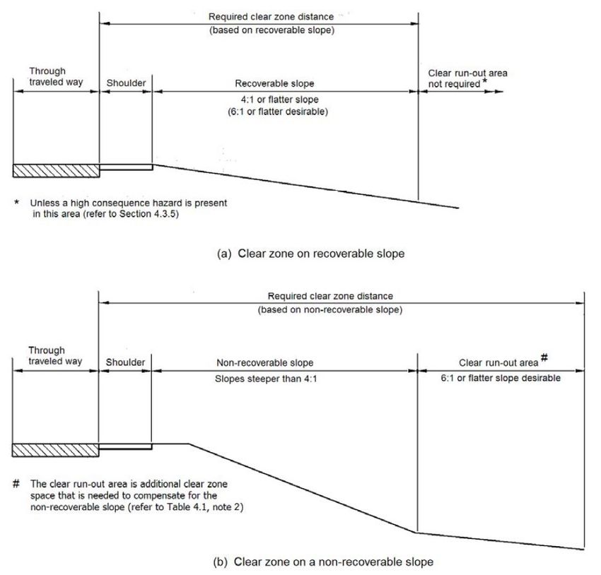
5.3.11       Wider medians.................................................................................................................. 22
             5.3.13       Barrier containment level required (Step B5) .................................................................... 22
             5.3.14       Barrier type (Step B6) ....................................................................................................... 24
             5.3.15       Determine the Working Width (Steps B7 to B9)................................................................ 26
             5.3.16       Determine vehicle roll allowance and system width (Step B8).......................................... 32
             5.3.17       Determine the working width (Step B9) ............................................................................ 32
             5.3.18       Barrier length of need (Step B11) ..................................................................................... 33
             5.3.19       Minimum length of barrier (Step B12) ............................................................................... 33
             5.3.20       Sight distance (Step B13) ................................................................................................. 34
             5.3.21       Terminals (Step B14)........................................................................................................ 35
             5.3.22       Transitions between barriers (Step B15) .......................................................................... 35
   5.4       General access through safety barriers .............................................................................. 36
             V5.4.1       General ............................................................................................................................. 36
             V5.4.2       Emergency services operation and access ...................................................................... 36
             V5.4.3       Maintenance and service authority access ....................................................................... 36
   5.5       Safety barrier and roadside amenity ................................................................................... 37
             V5.5.1       Barrier aesthetics.............................................................................................................. 37
             V5.5.2       Aesthetically pleasing barriers .......................................................................................... 37
   5.6       Other safety barrier design considerations ......................................................................... 38
             5.6.1        Barriers at intersections and driveways ............................................................................ 38
             V5.6.4       Delineation........................................................................................................................ 38
             V5.6.5       System height ................................................................................................................... 38
             V5.6.10      Sub-standard curves ........................................................................................................ 39
             V5.6.11      Curves on steep downgrades ........................................................................................... 39
             V5.6.12      Provision of paving adjacent to safety barriers ................................................................. 39
             V5.6.13      Audio Tactile Line Marking (ATLM) .................................................................................. 39
             V5.6.14      Provision for stopping ....................................................................................................... 39
             V5.6.15      Rural township considerations .......................................................................................... 40
             V5.6.16      Treatment of entry and exit ramps .................................................................................... 40
   5.7       Road safety barriers for vulnerable road users ................................................................... 41
             5.7.1        Motorcyclists ..................................................................................................................... 41

   6         Design for Steep Downgrades .................................................................... 43
   7         Work zone safety barrier systems .............................................................. 43
   References ............................................................................................................. 44
   Appendices ............................................................................................................. 45
             Appendix H – Examples of Length of Need Calculations .................................................................. 45
             Appendix I – Types of Safety Barrier Terminals ................................................................................ 45

   Appendix VA – Popular motorcycle routes in Victoria ......................................... 46
   Appendix VB – Effective Clear Zone ...................................................................... 54

Supplement to AGRD Part 6: Roadsides, Safety and Barriers (2020)
Version 4.0, August 2021                                                                                                                                             4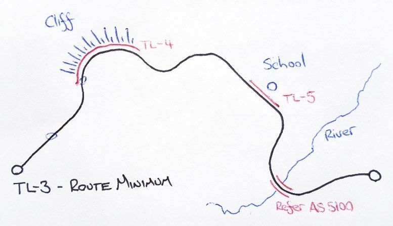
1 Introduction to Roadside Design
 IN DEVELOPMENT: Sections 1, 2 and 3 are currently being reviewed by DoT.
 As such, no new material or guidance has been added to Section 1, 2 or 3 in this version. DoT has simply
 removed material that is no longer relevant and has restructured the remaining material to suit AGRD Part 6

1.5     Principles considered in Roadside design to achieve the
        Safest System
Additional Information
The Department of Transport (DoT) is committed to the Safe System approach to road safety and to
creating a culture that seeks to improve road safety outcomes for the Victorian community. Run-off-
road and loss of control crashes are the cause of around one third of fatalities and serious injuries that
occur in Victoria. On country roads, the proportion is higher: approximately one half. Designing roads
and roadsides to minimise the chances of run-off-road and loss of control crashes and to mitigate the
severity of crashes that do occur is critical to progression towards the vision of zero fatalities and
serious injuries on Victorian roads.

1.6     Roadside Safety Design
Additional Information
The design of the roadside must take into consideration any features or objects that are beyond the
road reservation boundary that are likely to result in fatal or serious injuries if struck by an errant
vehicle. While road authorities may have limited powers with respect to infrastructure outside the road
reservation, measures such as the installation of roadside safety barriers to mitigate the outcome of
potential crashes should be considered.
In addition to providing the safest possible environment for road users, road authorities have an
obligation to provide a safe workplace for personnel involved in works, which includes maintaining
roads and roadsides, and repairing any infrastructure that is damaged by a crash (e.g. safety
barriers). The duty of care is set out in Clause 11 of the Road Safety Act 2004, Code of Practice,
Worksite Safety – Traffic Management (Victorian Government 2010).
Road and roadside design for errant vehicles must consider the risks to any person that may be
involved in works and the controls can be implemented to mitigate those risks.

1.6.4   Appropriate barriers and other treatments
Additional Information
Refer to the following guidelines relating to the prevention of head-on crashes:
    •   Section 5.4.3 of this Supplement for median barriers on divided highways and freeways with a
        posted speed limit of 100 km/h or higher,
    •   RDN 03-08 - Central Barrier in Narrow Medians,
    •   RDN 03-09 - Wide Centre Line Treatment (WCLT),

1.9     Calculating a risk score
1.9.4   Measuring the lateral distance to a hazard
Substitute Information
A prerequisite to the identification and assessment of hazards for both new roads and existing roads
is to ensure that the road itself is designed and maintained in a way that should enable drivers to keep
their vehicles on the road when travelling at an appropriate speed. Refer to Section 3.4 of AGRD Part
6 (Austroads 2011).

Supplement to AGRD Part 6: Roadsides, Safety and Barriers (2020)
Version 4.0, August 2021                                                                                       5
To provide a Safe System and contribute to a vision of zero fatal and serious injuries, the entire
roadside environment must be considered to have an element of risk and designed, as far as is
reasonably practicable, with the aim to eliminate that risk. Vehicles that leave the roadway can
potentially travel significant distances before recovering or decelerating to a speed that will ensure
that occupants are not fatally or seriously injured if a hazard is encountered (Austroads 2014, Doecke
& Woolley 2011). Historically, the band of interest has been taken as the clear zone. However,
research has indicated that the distance that vehicles may travel is well in excess of the width of the
clear zone.
The area of interest shall include all locations that can be feasibly accessed by an errant vehicle. It
shall comprise the longitudinal extent under consideration and the lateral extent, being the roadside
from the edge of the travelled way to the property boundary of the road and beyond if there are
hazards present that pose a risk of fatal or serious injury. Both sides of the road must be assessed.
There is limited information or research available relating to the lateral distance that may be traversed
by an errant vehicle that leaves that roadway. The distance travelled will depend upon a range of
variables, including speed, angle of departure and the surface type / condition. Table V1.1 provides
suggested values that can be used for the area of interest for different operating speeds. Table V1.1
relates to roadsides that are relatively flat. A wider band of interest may need to be considered where
the roadside slopes away from the roadway and there are high risk hazards (e.g. deep water) located
beyond the distances shown.
Table V1.1: Lateral extent of the area of interest
LATERAL EXTENT OF THE
SPEED LIMIT
AREA OF INTEREST
110 km/h 50 - 60 m
100 km/h 40 - 50 m
90 km/h 32 - 40 m
80 km/h 18 - 27 m
70 km/h 14 - 20 m
60 km/h 10 - 15 m
It must be noted that it is not intended that all hazards within the area of interest should be treated or
removed. In many situations, it is highly unlikely to be practical or cost effective to do so. The purpose
is to identify all hazards that pose a risk of high severity crashes, regardless of how far they are from
the road, so that treatment options that have the greatest potential to reduce FSI crashes are
considered.
1.9.11 Risk score charts for roadside safety barriers
While road safety barriers are not risk free (and may sometimes be classified as hazards), they are
often the preferred treatment, as they shield the isolated hazards, the background hazards, as well as
the rollover risk. On high speed, high volume roads in particular, continuous barriers are usually the
treatment option that most closely aligns with Safe System principles.
1.9.12 Hazards for motorcyclists and other vulnerable road users
Additional Information
Hazard identification in the context of motorcyclists shall consider the following:
• The concept of a hazard free zone beside a road is based on providing a driver the
opportunity to regain control of a vehicle. For motorcyclists, it also provides an area free of
obstructions in the event that a rider falls or is thrown from their motorcycle.
• Sealed shoulders in rural areas have been shown to be very cost effective in reducing run-off-
road crashes. For motorcyclists, who do not have a second pair of wheels to remain on the
road when veering off the road, the benefits may be significant. The most cost effective width
for sealed shoulders for motorcyclist safety is not known, any sealed shoulder width is safer
than unsealed shoulders.
Supplement to AGRD Part 6: Roadsides, Safety and Barriers (2020)
Version 4.0, August 2021 6• Barrier kerbing (B type) is a severe hazard to motorcyclists in the event of falling off their
motorcycle. Contrary to common perception, it provides little protection to pedestrians from
traffic. Where possible, semi-mountable kerb profiles should be used in preference to barrier
kerb.
• Lips or bullnoses on kerbs and raised concrete aprons can snag motorcycle foot pegs and
create instability when ridden over.
• Kerb colours which blend into road pavement colours, i.e. asphalt kerb, create inadequate
definition of vehicle paths and necessary tyre clearances in poor light conditions and should
not be used where alignments are tight or deviations in alignment are created.
DoT publication ‘Making roads motorcycle friendly (December 2014)’ provides additional information
and guidance regarding hazards and treatments to improve safety for motorcyclists. Section 5.7.1 of
this Supplement provides guidance relating to barriers and motorcyclist safety.
2 Network Risk Assessment
DoT has no supplementary comments for this section.
IN DEVELOPMENT: Sections 1, 2 and 3 are currently being reviewed by DoT.
As such, no new material or guidance has been added to Section 1, 2 or 3 in this version. DoT has simply
removed material that is no longer relevant and has restructured the remaining material to suit AGRD Part 6.
Supplement to AGRD Part 6: Roadsides, Safety and Barriers (2020)
Version 4.0, August 2021 73 Program and Project Risk Assessment
IN DEVELOPMENT: Sections 1, 2 and 3 are currently being reviewed by DoT.
As such, no new material or guidance has been added to Section 1, 2 or 3 in this version. DoT has simply
removed material that is no longer relevant and has restructured the remaining material to suit AGRD Part 6.
3.5 Step 3: Identify, evaluate and rank risk mitigation options
3.5.1 Identify the options
Additional Information
Designing to eliminate or mitigate roadside hazards is a significant challenge. Historically, the general
approach has been to identify and address hazards that are within a relatively narrow roadside
corridor known as the clear zone. The clear zone approach, which was first developed during the
1960s and 1970s, is based on the premise that 80 to 85 per cent of errant vehicles would be able to
recover or stop within a prescribed lateral distance from the roadway. Based on the Safe System
philosophy and the vision of eliminating fatalities and serious injuries from road crashes, an outcome
in which 15 to 20 per cent of run-off-road crashes are at risk of being high severity is considered
unacceptable. Accordingly, roadsides must be designed to eliminate the risk of fatal and serious
injuries from run-off-road events, as far as is practicable.
Potential treatment options should be identified with the aim to eliminate the risk of fatal and serious,
injuries, as far as is practically possible, in accordance with best practice and up-to-date knowledge.
While the ultimate objective is to eliminate the risks associated with roadside hazards, in practice it
will be necessary to consider the order of priority for considering treatment options. This will depend
on the context of the road, the likelihood of an errant vehicle encountering an identified hazard and
the likely severity of a crash involving the hazard.
For high speed roads, particularly those with high volumes such as M-Class and A-Class roads,
continuous safety barrier provides significant benefit for the level of investment and is the preferred
treatment to reduce the risk of fatal and serious injuries from run-off-road and head-on crashes.
3.5.2 Evaluate the risk associated with a roadside treatment using a qualitative
assessment
Additional Information
DoT practice is to minimise the risk of fatal and serious injury as far as practically possible in
accordance with best practice and up-to-date knowledge.
The qualitative assessment of treatment options shall consider how well each option aligns with Safe
System principles. Reference should be made to Austroads Safe System Assessment Framework
(Austroads 2016) for guidance on treatment hierarchy and selection (Section 4.6). Primary or
transformational treatments are preferred as they are more likely to eliminate the risk of fatal and
serious injuries.
Where appropriate, a Safe System Assessment should be conducted in accordance with DoT Safe
System Assessment Guidelines (2018) to evaluate treatment options.
3.5.2 Rank treatment options
Additional Information
The ranking of treatment options shall consider how well each option aligns with Safe System
principles. Reference should be made to Austroads Safe System Assessment Framework (Austroads
2016) for guidance on treatment hierarchy and selection (Section 4.6). Primary or transformational
treatments should be ranked higher than supporting treatments as they are more likely to eliminate
the risk of fatal and serious injuries.
Supplement to AGRD Part 6: Roadsides, Safety and Barriers (2020)
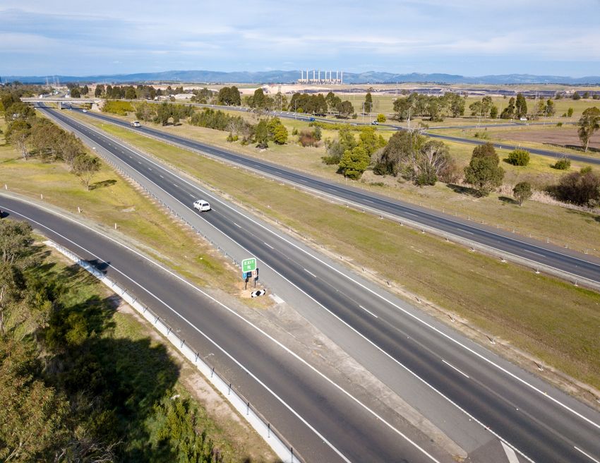
Version 4.0, August 2021 84 Treatment Options Please Note: The Department of Transport (DoT) is working closely with Austroads on project SRD6289 to update Sections 4, 5 and 6 of the AGRD Part 6. When this is complete, Sections 4, 5 and 6 of the Supplement will be updated to suit. In this version, no new material or guidance has been added to Section 4. DoT has simply removed material that is no longer relevant and has restructured the remaining material to suit AGRD Part 6. 4.1 General DoT has no supplementary comments for this section. 4.2 Summary of Treatment Options Additional Information While the clear zone approach is not to be used to determine the area of interest, it may be used to define the roadside area that is of highest risk for the purpose of prioritising treatments. Removing hazards from the clear zone or modifying them to reduce the risk of fatal and serious injuries may be a cost-effective treatment option for some contexts where safety benefits can be quantified. The width of the clear zone shall be determined in accordance with Appendix VB. However, research shows that around 30% of run-off-road casualty crashes occur on roads where there are clear zones greater than 13 m (Austroads 2011). In addition, the research indicates that there is an increase in roll-over crashes as the clear zone increases. Accordingly, treatment options for all hazards within the area of interest shall be considered. Continuous Safety Barrier Continuous safety barrier refers to the design and installation of longitudinal barriers (including median and centreline barriers) along an entire or extended length of road. All roadsides contain various elements that contribute to the risk of fatal and serious injuries for occupants of errant vehicles. The intent of continuous barrier is to maximise protection against all roadside risks and head-on crashes by installing a device that is forgiving. A continuous safety barrier will incorporate provisions for access for emergency and maintenance purposes. Breaks at adjoining roads and properties may also be provided but should be minimised as far as is practically possible. Continuous barriers are generally recognised as a Safe System treatment for vehicles that encroach into the roadside. They are often the preferred treatment option, particularly on high volume, high speed roads. Treatment types (other than continuous barrier) to address specific hazards are discussed in Section 5.4 of AGRD Part 6 (Austroads 2011) and this Supplement. While continuous safety barrier can be implemented on any road, it provides the most effective safety outcome for the level of investment required on high-speed roads with sealed shoulders, minimal access points and few constraints; hence it is optimal for routes that connect capital cities, major provincial centres or link major centres of production. Continuous safety barrier aims to protect the entire roadside, yet some areas cannot be protected due to constraints that prohibit the installation of barrier (e.g. driveways, intersections). The residual risk of these areas must be assessed and treated where possible (removed or relocated), although in some situations (often urban), the frequency of constraints may be too high, and the effectiveness of continuous safety barrier may not be achieved. In Victoria, continuous safety barrier should be the first (preferred) option on roads with a posted speed limit of 80km/h and above, and considered on lower speed roads. Supplement to AGRD Part 6: Roadsides, Safety and Barriers (2020) Version 4.0, August 2021 9
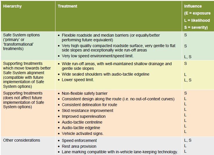
4.3     Effectiveness of Treatment Options
Additional Information
To be consistent with the Safe System approach, treatment options should be classified as primary
(or transformational) or supporting treatments.
Primary treatments are those measures that have the potential to eliminate or come close to
eliminating the risk of fatal and serious injury (FSI) crashes.
Supporting treatments are effective in reducing the risk of FSI crashes but not to the extent of a
primary treatment (i.e. there is a residual moderate or significant FSI crash risk). Implementation of a
primary treatment should be given priority over a supporting treatment that may be targeting a similar
crash risk.
Table V4.1 shows a list of run-off-road treatments, classified in accordance with their alignment with
Safe System principles. Refer to Austroads Safe System Assessment Framework (Austroads 2016)
for treatments for head-on crashes and further information regarding primary and supporting
treatments in general.
Table V4.1: Hierarchy of Run-off-road Treatments (Source: Austroads 2016)

4.4     Types of Treatment
4.4.1   Treatments for Trees
Additional information
Refer to VicRoads Tree Policy (VicRoads 2016) for information and guidance on managing trees
within road reserves for which DoT is the Coordinating Road Authority.

Supplement to AGRD Part 6: Roadsides, Safety and Barriers (2020)
Version 4.0, August 2021                                                                                   10
4.4.3   Treatments for Medians
Additional information
Median barriers shall be used to reduce the incidence of head-on crashes and the severity of run-off-
road crashes on new freeways and divided highways with a proposed speed limit of 100km/h or more.
Median barriers should also be considered on divided roads with speed limits of less than 100 km/h to
reduce the risk of fatal and serious injuries from run-off-road and cross-median crashes.
Treatment options to address the risk of head-on and / or run-off-road to the right crashes on
undivided roads include centre line barriers and wide centre lines. For detailed guidance on these
treatments refer to RDN 03-08 Central Barrier in Narrow Medians (VicRoads 2018) and RDN 03-09
Wide Centre Line Treatment (VicRoads 2018).

4.4.5   Treatments for Drainage Features
Additional Information

Recoverable Slopes
To be recoverable, batter slopes desirably should be 4:1 or flatter. To be relatively safe for trucks,
batter slopes should be 6:1 or flatter. Refer Section 4.5 of the Supplement to AGRD Part 3.

Pipes and culverts perpendicular to the road – height 0.6 m maximum
For pipe diameter or box culvert heights up to 0.6 metres, refer to Standard Drawing SD1992
(VicRoads 2019) for details of the traversable endwall.
The channel downstream preferably should not be deeper than the height of the culvert. Rock
beaching will be required to prevent erosion of the batter and the channel. Beaching within the area of
interest or, as a minimum, the clear zone must be traversable, relatively smooth and no steeper than
4:1. Any rough textured beaching for energy dissipation shall be located beyond area of interest of the
clear zone.

Pipes and culverts perpendicular to the road – height 0.6 m to 2.0 m
For pipe diameter or box culvert heights between 0.6 metres and 2.0 metres, safety barrier protection
is preferred. Alternatively, where the risk is acceptable, designers may consider extending the pipe or
box culvert to the edge of the area of interest or, as a minimum, the clear zone (refer Appendix ##),
and to warp the batter around the culvert using driveable batter slopes.
Where it is not practical to extend the culvert, or where regular maintenance can be assured, grates
may be provided to span between the wingwalls. Each grate must be hydraulically and structurally
adequate.
Safety barrier shall be provided where the height exceeds 2.0 metres

Pipes and culverts parallel to the road
Conventional endwalls on culverts under driveways and median openings are hazardous because
they can be hit head on. The preferred treatment is to locate them outside the area of interest or, as a
minimum, the clear zones of traffic flows in both directions. If the endwall cannot be located beyond
the clear zone, provide a traversable endwall with transverse bars as shown on Standard Drawing
SD1991.

4.4.9   Treatments for Poles
Additional Information
For details relating to the assessment and treatment of utility poles, refer to RDN 06-03 Roadside
Utility Poles (2013). All poles within the area of interest as defined in Section 4.2.2 of this Supplement
should be assessed and considered for treatment. The assessment methodology set out in RDN 06-
03 should be applied but not restricted to poles within the clear zone.

Supplement to AGRD Part 6: Roadsides, Safety and Barriers (2020)
Version 4.0, August 2021                                                                                     11
V4.4.12         Treatments for Verges and Fill Slopes
Additional Information
When considering treatments for verges, the risk of roll-over crashes shall be taken into account.
While it may be possible to remove rigid hazards such as poles and trees, on many roads it is not
practical to maintain verges to the standard that is required to minimise the likelihood that an errant
vehicle will overturn. The installation of continuous road safety barriers is often the preferred
treatment, particularly on high volume, high speed roads.

Supplement to AGRD Part 6: Roadsides, Safety and Barriers (2020)
Version 4.0, August 2021                                                                                  12
5 Road Safety Barriers
 Please Note: The Department of Transport (DoT) is working closely with Austroads on project SRD6289 to
 update Sections 4, 5 and 6 of the AGRD Part 6. While Section 5 has been updated significantly in the version,
 in order to support the consolidation of existing barrier design guidelines and the RDN 06-04 (v16) restructure,
 much of this content will be embedded within AGRD Part 6 during project SRD6289. When this is complete,
 Sections 4, 5 and 6 of this Supplement will be updated to suit.

5.1      Introduction
5.1.1    General
Additional Information
Only road safety barriers, variants and end treatments accepted by DoT shall be used on the declared
road network.
For further details on acceptable barrier systems, refer to RDN 06-04 - Accepted Safety Barrier
Products.
The protection of pedestrians and cyclists should also be considered during design (e.g. barriers may
be required to be provided where a shared path is adjacent to an urban freeway). Care should be
taken in the selection of barrier type in high pedestrian and cyclist areas to ensure appropriate
barriers are selected. Safety barriers shall not be used to shield commercial developments and
private residences unless there is an established crash history, the potential for crashes is high or the
potential for harm is high.

V5.1.3 Warrants – General
Additional Information
Engineering judgement based on the site conditions, current road safety practice and relevant
corridor/network safety plans needs to be exercised in determining where a safety barrier is required.
The warrants to install barrier may not apply where traffic volumes are low, a consistent road safety
risk environment is provided, and speeds are restricted by the road alignment to less than 60 km/h; or
where the benefit-cost ratio is extremely low.

V5.1.4 Design notation
Additional Information
The DoT Final Drawing Presentation Guidelines provide only specific line styles for Guard Fence
(GF), Wire Rope Safety Barrier (WRSB) and concrete barriers. As such, to avoid any confusion in the
design, review, or construction process when barrier products are specified, they shall be
accompanied by a note which specifies the type of system designed along with the Test Level. This
note shall use the terminology as follows:
  •     “TL-# Flexible WRSB" for Wire Rope Safety Barrier products
  •     “TL-# Flexible GF" for Flexible Guard Fence products
  •     "TL-# Semi-Rigid GF" for public domain, semi-rigid, Guard Fence
  •     “TL-# Concrete barrier” for roadside concrete barriers.
The '#' symbol specifying test level would be filled in as appropriate by designers (e.g. TL-3 or TL-4).
It is important to include the minimum test level as this is a design decision and may limit the number
of suitable products that can be selected. e.g. Thrie-beam products fall under the ‘semi-rigid’
category.
Alternatively, where a proprietary system has been specifically included in a design to meet a
particular requirement, the note can specify the system by name and optionally include the
terminology "or equivalent" where an alternative may be used.

Supplement to AGRD Part 6: Roadsides, Safety and Barriers (2020)
Version 4.0, August 2021                                                                                            13
5.2     Factors considered in barrier selection
5.2.1   Site conditions
Additional Information

Maintenance
While the provision of barrier maintenance strips, concrete or otherwise, is not required, exceptions
may be made if it can be shown that maintenance strips offer greater benefits, on a whole-of-life
comparison, over alternative practices. Applications for an exception must demonstrate the
consideration of current technology including mowing equipment and/or alternative maintenance strip
materials such as controlled grasses or geotextiles.
Where concrete maintenance strips are to be provided, they shall be installed in accordance with the
requirements of Standard Drawing SD 3503, Standard Section 708 and Standard Section 711.

Urban environments
Where continuous barrier is being applied in an urban environment, the designer must consider the
impact of barrier on other road user functions, such as:
    •   pedestrian and cyclist access and connectivity
    •   DDA requirements
    •   bus access and routes
    •   local events
    •   local services (e.g. waste management).

5.3     Road safety barrier design process
5.3.1   Outline of process

V5.3.1.1         Design process for continuous safety barrier
Unlike the traditional targeted barrier approach, continuous safety barrier should be treated like a
longitudinal component of the road, intended to shield all roadside elements as effectively as possible.
This includes all hazards within the ‘area of interest’ (not only within the clear zone), areas of flat
terrain that may cause roll-over, and cut embankments irrespective of grade.
As such, some typical barrier design steps are often less critical (e.g. hazard identification and barrier
length of need) given the focus on protecting the entire road length, while others are more important
(e.g. offset to travel lane and sight distance).
When designing continuous safety barrier, the key focus of design should be providing:
    •   a maximum protected length/area
    •   a suitable and functional safety barrier that performs optimally during impact
    •   a barrier that aids safe and sustainable operation and maintenance of the road and roadside.
In addition, all unprotected areas or hazards should be recognised and assessed with an attempt to
mitigate risk with other treatments.
While continuous safety barrier manages risk associated with high operating speeds, the actual safety
risk will depend on the frequency of constraints that prohibit the installation of barrier (e.g. side roads,
access points/driveways and median openings). These locations will have a different risk profile than
sections where access is prevented.
As such, speed management treatments (e.g. reduced speed limits and speed calming treatments)
may be needed in combination with continuous safety barrier where:

Supplement to AGRD Part 6: Roadsides, Safety and Barriers (2020)
Version 4.0, August 2021                                                                                       14
• continuous safety barrier cannot be achieved due to the frequency of side roads, access
points/driveways and median openings, as well as pedestrian activity and the amenity
requirements of councils
• the subject road length has a high frequency of at-grade intersections or pedestrian crossings
and the risk of vehicle-vehicle and vehicle-pedestrian crashes can be mitigated through speed
management (e.g. reduced speed limits)
• the existing road geometry is less than suitable for the current operating speed and can be
supported by crash history. An assessment of the road geometry including horizontal
curvature, cross fall, existing sight lines, and other factors, should be undertaken to
demonstrate the benefits of speed management.
5.3.3 Determine the objectives of the safety barrier
Objectives of continuous safety barrier
Continuous safety barrier refers to the design and installation of barrier along the entire road length to
protect errant vehicles from potentially rolling, impacting a hazard, or causing a head-on collision
when leaving the road.
Rather than designing a barrier to shield a specific hazard(s), continuous safety barrier should be
designed as a longitudinal element of the road, with an objective to maximise road user safety. Refer
Section V6.3.1.1.
5.3.4 Determine the lateral position of the barrier (Step B3)
Additional Information
In general, provided that the roadside would enable an errant vehicle to recover, it is desirable that
road safety barriers be located (e.g. offset, lateral position) as far as possible from the edge of the
traffic lane as site conditions permit. This will maximise the opportunity for drivers to regain control of
the vehicle and minimise the frequency of barrier impacts. However, it is to be noted that a greater
offset from the edge of the traffic lane can result in larger impact angles, higher impact severity and a
higher probability of the barrier being penetrated.
Figure V5.1 below illustrates some of the cross-section elements relating to barriers installed on
verges.
Figure V5.1: Verge barrier location (Source: QTMR)
Supplement to AGRD Part 6: Roadsides, Safety and Barriers (2020)
Version 4.0, August 2021 15It is ideal that the slope between the traffic lane and safety barrier is essentially flat. However, where
the barrier is located beyond the verge, installation of safety barriers on steeper slopes is acceptable
in accordance with Table V5.1.
Table V5.1: Minimum slopes between the traffic lane and safety barrier
Project type Minimum slope
New construction 10:1 or flatter
Retrofitting barriers to existing road 6:1 or flatter
When safety barriers are placed on slopes steeper than 10:1, studies have shown that for certain
encroachment angles and speeds, the barrier may not perform as intended. Commentary 6 from
AGRD Part 6 must be considered and a barrier free area from hinge point to 3.8 m beyond the hinge
point on a 6:1 slope should be adopted. Slope rounding is also recommended. Safety barriers must
not be placed on batters steeper than 6:1, therefore, they must be placed adjacent to the traffic lane
according to the offset criteria.
Changes in lateral position
Varying offsets to road safety barriers along a length of road may cause delineation issues at night.
Varying offsets of delineators on barriers may be confusing in the dark because steps in the barrier
offset create a broken line of reflectors that is not consistent with the lane marking. In such
circumstances, designers should consider omitting the delineators on barriers and use alternative
delineation (e.g. raised reflective pavement markers and guideposts).
At night, a large offset between a road safety barrier and the edge of the traffic lane can give the
impression that an extra lane is available between the edge line and the barrier. This may lead to
crashes where drivers have moved onto the shoulder and verge in the mistaken belief that an extra
lane is available. Hence, in situations with barrier offsets greater than 4m, delineators shall not be
used. Alternative delineation should be provided closer to the road. Refer the Supplement to
AS 1742.2.
5.3.5 Offset to traffic lane
Additional Information
Safety barriers should be placed at appropriate distances from the edge of the traffic lane. The on-
going maintenance of the areas on both sides of the barrier should be considered. The whole-of-life
cost, practicality and Occupational Health & Safety implications of these areas must be considered in
accordance with Section 28 of the OH&S Act 2004.
Barrier offsets should be maximised where possible. The desirable offset for safety barriers from the
nearest traffic lane is 4.0 m-6.0 m, with a minimum offset of 3.0 m. Every effort should be made to
achieve the desirable offset of 4.0 m as it allows broken down vehicles to pull over clear of traffic
lanes and provides space for maintenance vehicles and workers. It also maximises the opportunity for
the driver of an errant vehicle to recover control before striking the barrier.
Barrier offset requirements between traffic lanes and all barrier types for rural and urban roads are set
out in Table V5.2. Barrier offsets greater than 6.0 m should be avoided but may be limited to a
specific need such as an emergency stopping bay or maintenance access.
Supplement to AGRD Part 6: Roadsides, Safety and Barriers (2020)
Version 4.0, August 2021 16Table V5.2: Clearance from traffic lane to face of barrier (m)
Location Rural Urban Comments
NDD Desirable 4.0 – 6.0 3.0 – 6.0 Maximum length of offsetTable V5.2A - Barrier offset assessment
No. Topic Yes/No Comment or mitigation
1 Constraint management
1.1 Can the site constraints (e.g. trees, poles, batters, etc.)
be removed, relocated or modified to increase barrier
offset?
1.2 Can a stiffer barrier system be used to increase barrier
offset?
1.3 Where speed limits are 80 km/h or less, has a reduced
working width been considered to increase barrier
offset?
2 Provision for stopping
2.1 Is there sufficient opportunity for a vehicle to pull over?
2.2 Have emergency stopping bays or breaks in the barrier
been provided?
2.3 Is a motorist able to identify safe locations to stop both
at day times and night times (e.g. signs, other advisory
information or self-explaining roadside)?
2.4 On divided roads where a 3 m offset cannot be provided
on the median side, have stopping opportunities on the
left side of the road been maximised?
2.5 Is there an increased risk of rear-end collisions involving
a disabled vehicle (e.g. reduced sight distance or
inability to pass)?
3 Nuisance impacts
3.1 Have adequate traffic lane widths been provided?
3.2 Is the operating speed and road geometry likely to
increase the frequency of nuisance impacts?
3.3 Has shoulder sealing between the traffic lane and barrier
been provided for errant vehicles to re-gain control?
Has audio tactile edge line marking been provided?
3.4 Has the appropriate type of barrier been used? - Barriers
that remain operational after an impact should be used
where there is a high risk of repeat impacts before
repairs can be made.
3.5 Is fatigue a historical issue along this route?
4 Sight distances
4.1 IMPORTANT: Is there sufficient sight distance to/for
access roads and intersections?
4.2 Is there sufficient sight distance to a potentially disabled
vehicle protruding onto the traffic lane?
4.3 Is there sufficient sight distance to potential roadside
hazards?
5 Maintenance
5.1 Can barrier maintenance activities (e.g. inspection,
repairs to barrier, grass mowing and weed spraying) be
carried out safely?
5.2 Can nearby assets be safely accessed (e.g. structures,
signs, lighting or vegetation)?
Supplement to AGRD Part 6: Roadsides, Safety and Barriers (2020)
Version 4.0, August 2021 18Continuous barrier offsets on high-speed rural roads
Continuous safety barrier transforms how people use and maintain the road, therefore, providing an
effective and operational barrier offset is especially important.
Every effort should be made to achieve the desired barrier offset of 4.0 m, particularly on
freeways/highways, as it allows broken down vehicles to pull over clear of traffic lanes and provides
space for maintenance vehicles.
• Provision for stopping: Rural roads typically have fewer access points than urban roads,
therefore road users are more likely to stop on the roadside. Where the barrier offset is below
minimum, regular ‘emergency stopping bays’ must be provided in accordance with Section V5.7.14
and motorists must be able to identify safe locations to stop. Median barrier offsets between 2.0 m-
3.0 m should be avoided to discourage vehicles from pulling over into a narrow shoulder.
• Nuisance impacts: Fatigue-related crashes are more common on rural roads/highways than on
urban roads. Drivers leaving the road require time (and lateral distance) to recover. Where the
barrier offset is below minimum, audio tactile line marking should be provided.
• Sight distance: Below minimum barrier offsets must be avoided on crests and curves where
available sight distance is deficient.
• Maintainability: On rural roads, barrier inspection and repair is often undertaken adjacent to high
speed traffic. Where the barrier offset is below minimum, an appropriate barrier type should be
considered, and the barrier layout should enable safe maintenance. Refer
Section 5.7.
Additional commentary and typical design philosophy for continuous barrier on high speed rural roads
is provided in RDN 06-16 – Barrier design commentary
Figure V5.2 – Typical cross section of continuous barrier on high-speed rural roads
Continuous barrier offsets on urban roads
Continuous barrier offsets on urban roads should be maximised where possible and the desirable
offset from the nearest traffic lane is 3.0 m - 6.0 m. However, recognising that urban roads operate
differently to rural high-speed roads, a suitable barrier offset will depend on context. In addition, most
urban roads have kerb installed, which will limit the barrier offset ranges (see below).
• Provision for stopping: Urban roads typically have frequent access points for vehicles to pull
over. To support discretionary and non-discretionary stopping, motorists must be able to identify
safe locations to stop. This will depend on the access types, intersecting roads and signage
scheme.
• Nuisance impacts: While motorists may be overall more alert on urban roads, there are more
distractions, decisions, and manoeuvres for an individual motorist to manage. Nuisance impacts
on urban roads are more frequent near turning movements or where lane widths are below
minimum. Designers should avoid compounding factors such as reduced lane widths, lane
changing and turning manoeuvres.
• Sight distances: Safe intersection and gap selection sight distances are critical in urban
environments.
Supplement to AGRD Part 6: Roadsides, Safety and Barriers (2020)
Version 4.0, August 2021 19• Maintainability: On urban roads, barrier inspection and repairs are often undertaken adjacent to
high volumes of traffic. Where the barrier offset is below minimum, an appropriate barrier type
should be considered and the barrier layout should enable safe maintenance. Refer Section 5.7.
Barrier setback from kerb
When barrier is positioned behind a kerb, the vehicle’s trajectory is first affected by the kerb, which
can result in the vehicle not engaging with the barrier effectively.
The vehicle trajectory will depend on several variables such as vehicle speed & angle, kerb height &
shape, and the vehicle’s tyre & suspension characteristics. However, Troutbeck (2020) notes that
“there is no easily recognised relationship between the kerb profile and the likely interaction [and]
flatter or steeper kerbs have approximately the same effect on the vehicle trajectories”.
This makes it difficult to predict the vehicle trajectory path, especially at high-speeds, therefore
locating the barrier close to ‘face of kerb’ is preferred in order to minimise the risk of vaulting. While
this objective must be balanced with the opposing objective to maximise barrier offsets, designers
should consider the site-specific risks of adopting a reduced barrier offset (refer Table V5.2A), before
adopting the maximum setback value.
In rural situations drainage should be designed so that it is not necessary to place a kerb under or in
front of a barrier.
In urban situations, where the road design cannot eliminate the ‘kerb-barrier’ interaction, the barrier
setback distance from kerb is to be in accordance with Table V5.3 which replaces Table 5.3 in AGRD
Part 6.
Table V5.3: Barrier setback distances from kerb
Operating Barrier type
Design
Kerb type Speed
Domain All FGF & WRSB3 GF
(km/h)
> 80 NDD Not permitted
Barrier
70 - 80 NDD 0 m – 0.2m 4.5 m 7m+
(>100mm height)
< 70 NDD 0 m – 0.2m 2.5 m 6m+
> 80 NDD 0.2 m – 0.4m 4.5 m 6m+
NDD 0.2 m – 0.4m 4m 5m+
Semi-mountable 70 - 80
EDD 0.4 m – 0.6m - -
(50-100mm height)
NDD 0.2 m – 0.4m 2.5 m 4m+
< 70
EDD 0.4 m – 1.0 m - -
Mountable
No restrictions
(Most obviously, Table V5.3 no longer contains guard fence setback distances of 0.1m to 1.0m (from back of kerb), which limits the offset to traffic lane, when a kerb is installed on the edge line. However, in recognition of the ongoing in-field performance of the former setback range, DoT provides an Extended Design Domain (EDD) setback range for use in constrained urban situations. Refer Table V5.3. These ranges help designers achieve a barrier offset to traffic lane of 0.6m and 1.0m, in 70-80km/h and
Post embedment depth may be an option to provide sufficient lateral support in semi-rigid systems.

                          Table V5.6: Support Width for Different Barriers

        System type                 Support width
        WRSB                        1.0 m
        Flexible W-beam             0.5 m
        Public domain W-beam
        Thrie-beam
        Permanent concrete          Varies
        barrier                     0m where barrier is part of a structure (e.g. Retaining wall) and
                                    designed in accordance with AS5100 and BTNs.

5.3.8   System width
Additional Information
The width of each road safety barrier system can be found in the Austroads or DoT TCU.

5.3.10 Narrow medians
Additional Information
Narrow medians are defined as medians with a width less than 6.2 m measured between edge lines
of opposing traffic lanes.
Further guidance on barriers in narrow medians is given in RDN 03-08 - Central Barrier in Medians
and the Supplement to AGRD Part 3.

5.3.11 Wider medians
Additional Information
Wider medians are defined as medians with a width of 6.2 m or greater.
To minimise the risk of fatal and serious injuries, safety barriers in medians should be located such
that they satisfy the offset requirements for both traffic directions (e.g. 6 m - 4 m offset) which will
result in the use of two barrier runs where the median is greater than 10 m.
While two runs are desirable, it may not be practical for all road sections, therefore, one run of barrier
may be considered in the median where the following conditions are all met:
    •   there are no fixed hazards within the median OR all fixed hazards can be removed
    •   the grade throughout the median is no steeper than 10:1 OR can be re-graded as such
    •   the barrier can be located such that it satisfies the offset requirements for one direction and
        will allow for the retrospective installation of a second run of safety barrier should there be a
        future need
    •   the barrier can withstand impacts from both directions (e.g. back-to-back variant).
Where any one of the above conditions is not met, two runs of safety barrier should be installed in the
median. Both runs of barrier should be designed to meet the principles contained within this
document.

5.3.13 Barrier containment level required (Step B5)
Additional information
Barrier containment level selection cannot be defined prescriptively for an entire network; rather it
must be determined using engineering judgement and information obtained from a site-specific risk
assessment. Over the length of a route, the containment level may vary based on the combination of
risk factors and site-specific conditions.

Supplement to AGRD Part 6: Roadsides, Safety and Barriers (2020)
Version 4.0, August 2021                                                                                     22
You can also read