Phoenix-S/-XNS Performance Validation - Space Flight Technology, German Space Operations Center (GSOC) Deutsches Zentrum für Luft- und Raumfahrt ...
←
→
Page content transcription
If your browser does not render page correctly, please read the page content below
Space Flight Technology, German Space Operations Center (GSOC)
      Deutsches Zentrum für Luft- und Raumfahrt (DLR) e.V.

Phoenix-S/-XNS Performance Validation

                  O. Montenbruck, C.Renaudie

                  Doc. No.   :   GTN-TST-0120
                  Version    :   1.0
                  Date       :   Apr. 5, 2007
Document Title: ii Phoenix-S/-XNS Performance Validation Document Change Record Issue Date Pages Description of Change 1.0 Apr. 5, 2007 All First release Document No. Issue 1.0 GTN-TST-0120 Apr. 5, 2007 DLR/GSOC No part of this document shall be reproduced in any form or disclosed to third parties without prior authorization.
Document Title: iii Phoenix-S/-XNS Performance Validation Table of Contents Document Change Record ....................................................................................................ii Table of Contents ..................................................................................................................iii Acronyms and Abbreviations ..............................................................................................iv Scope.......................................................................................................................................1 1. Introduction.......................................................................................................................3 1.1 Phoenix Receiver Description ....................................................................................3 1.2 Test Environment and Configuration ..........................................................................5 1.3 Test Matrix..................................................................................................................6 1.4 Receiver Configuration...............................................................................................7 2. Aeolus Scenario Definition ..............................................................................................8 2.1 Simulator Setup..........................................................................................................8 2.2 GPS Constellation ......................................................................................................9 2.3 Atmospheric Characteristics.....................................................................................11 2.4 Spacecraft Orbit and Attitude ...................................................................................11 2.5 Antenna Diagram .....................................................................................................15 3. Acquisition Performance ...............................................................................................16 3.1 Cold Start Acquisition ...............................................................................................16 3.2 Hot Start Acquisition.................................................................................................17 4. Tracking Performance....................................................................................................18 4.1 Carrier-to-Noise Density...........................................................................................18 4.2 Channel Allocation ...................................................................................................19 4.3 Raw Measurement Accuracy ...................................................................................20 5. Timing Performance .......................................................................................................25 5.1 Oscillator Drift...........................................................................................................25 5.2 Pulse-Per-Second Signal .........................................................................................26 6. Navigation Performance ................................................................................................27 6.1 Kinematic Navigation Accuracy ................................................................................27 6.2 Dynamically Filtered Navigation Accuracy ...............................................................31 6.3 POD Performance ....................................................................................................35 Summary and Conclusions .................................................................................................37 References ............................................................................................................................38 Annex ....................................................................................................................................39 A.1 YUMA Almanac for DLR_AEO Scenario ..................................................................39 Document No. Issue 1.0 GTN-TST-0120 Apr. 5, 2007 DLR/GSOC No part of this document shall be reproduced in any form or disclosed to third parties without prior authorization.
Document Title: iv Phoenix-S/-XNS Performance Validation Acronyms and Abbreviations ADM Atmospheric Dynamics Mission C1 RINEX identifier for C/A code measurements (on L1) C/A Coarse/Acqusition Code C/N0 Carrier-to-Noise ratio [dB-Hz] D1 RINEX identifier for Doppler measurements on L1 DLL Delay-Locked Loop DLR Deutsches Zentrum für Luft- und Raumfahrt DOP Dilution Of Precision FLL Frequency-Locked Loop GPS Global Positioning System GSOC German Space Operations Center IGS International GNSS Service L1 GPS frequency (1575.42 MHz) LA RINEX identifier for carrier phase meas. On L1 (C/A-code loop) LEO Low Earth Orbit n/a Not available, not applicable NVM Non-Volatile Memory PDOP Position Dilution of Precision PLL Phase-Locked Loop POD Precise Orbit Determination ppm Parts-Per-Million PPS Pulse-Per-Second PRN Pseudo-Random Noise PVT Position, Velocity, Time R/F Radio Frequency RINEX Receiver Independent Exchange Format rms Root Mean Square RTC Real-Time Clock SGPS Spaceborne GPS SNR Signal-to-Noise Ratio TCXO Temperature Controlled Oscillator TEC Total Electron Content TECU TEC unit (1016e-/m2) TTFF Time-To-First-Fix UERE User Equivalent Range Error VTEC Vertical Total Electron Content XNS eXtended Navigation System Document No. Issue 1.0 GTN-TST-0120 Apr. 5, 2007 DLR/GSOC No part of this document shall be reproduced in any form or disclosed to third parties without prior authorization.
Document Title: 1 Phoenix-S/-XNS Performance Validation Scope This document provides an analysis of GPS data collected during the functional and per- formance testing of an engineering model of the Phoenix-S/-XNS receiver in a signal simula- tor testbed. The report covers the proper operation of the core tracking and positioning func- tions of as well as the eXtended Navigation System. It is applicable for receiver software ver- sions D09B and up. Document No. Issue 1.0 GTN-TST-0120 Apr. 5, 2007 DLR/GSOC No part of this document shall be reproduced in any form or disclosed to third parties without prior authorization.
Document Title: 2 Phoenix-S/-XNS Performance Validation Document No. Issue 1.0 GTN-TST-0120 Apr. 5, 2007 DLR/GSOC No part of this document shall be reproduced in any form or disclosed to third parties without prior authorization.
Document Title: 3
Phoenix-S/-XNS Performance Validation
1. Introduction
1.1 Phoenix Receiver Description
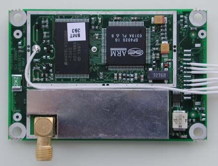
The Phoenix GPS receiver ([1], [2]) is a miniature receiver specifically designed for high dy-
namics space applications. It is based on SigTech’s commercial-off-the-shelf MG5001 re-
ceiver board but operates a proprietary firmware developed by DLR. Though originally de-
signed for automotive applications, the receiver board has been qualified for space use in a
series of thermal-vacuum, vibration and total ionization dose tests. The receiver employs a
GP4020 baseband processor which combines a 12 channel GP2021 correlator and an
ARM7TDMI microprocessor kernel. At a power consumption of less than one Watt and a
board size of 50 x 70 mm the receiver is among the smallest of its kind and particularly well
suited for satellites with limited onboard resources. The Phoenix receiver is extensively used
in European sounding rocket missions and has been selected for various other micro-satellite
missions in low Earth orbit (LEO) such as PROBA-2, X-Sat, ARGO, Flying Laptop and
PRISMA.
Fig. 1.1 Phoenix GPS Receiver
For satellite applications, two different versions of the Phoenix receiver are available to cover
different mission needs:
• The Phoenix-S receiver provides basic GPS tracking and navigation functions for
LEO satellites . It offers a built-in orbit propagator to aid the initial acquisition and to
allow a short time-to-first-fix. Low-noise code and carrier phase measurements are
achieved through carefully optimized tracking loops. Full cycle integer ambiguities
enable precision relative navigation in carrier phase differential GPS applications.
• The Phoenix-XNS extends the functionality of the basic receiver version by a built-in
navigation filter for LEO satellites ([3], [4]). It offers a dynamically smoothed and con-
tinuous navigation solution even in case of limited GPS satellite visibility. The meas-
urement processing inside the Phoenix-XNS provides a rigorous elimination of iono-
spheric path delays and enables a real-time navigation accuracy meeting the re-
quirements of advanced remote sensing satellites.
The Phoenix-XNS receiver requires a larger memory but is otherwise compatible with the
basic Phoenix-S model. All test results on the acquisition, tracking, and kinematic navigation
performance provided that are provided later in this report are equally applicable for both
versions.
Specific features of the Phoenix-S/-XNS receiver software for LEO applications include opti-
mized tracking loops for high accuracy code and carrier tracking, precision timing and integer
Document No. Issue 1.0
GTN-TST-0120 Apr. 5, 2007
DLR/GSOC No part of this document shall be reproduced in any form or disclosed to third parties without prior authorization.Document Title: 4 Phoenix-S/-XNS Performance Validation ambiguities for carrier phase based relative navigation, a twoline elements orbit propagator for signal acquisition aiding, and an attitude interface to account for non-zenith pointing an- tennas in the channel allocation process. A pulse-per-second signal enables synchronization to GPS (or UTC) time with an accuracy of better than 1µs. Noise levels of 0.4 m (pseudo- range) and 0.5 mm (carrier phase) at representative signal conditions (C/N0=45dB-Hz) have been demonstrated in signal simulator and open air tests which render the receiver suitable for precise orbit determination. While the instantaneous (kinematic) navigation solution is restricted to an accuracy of roughly 10m (3D rms) due to broadcast ephemeris errors and unaccounted ionospheric path delays, an accuracy of about 0.5-1m can be achieved in a ground based precise orbit determination. Document No. Issue 1.0 GTN-TST-0120 Apr. 5, 2007 DLR/GSOC No part of this document shall be reproduced in any form or disclosed to third parties without prior authorization.
Document Title: 5
Phoenix-S/-XNS Performance Validation
1.2 Test Environment and Configuration
All tests described in this report have been conducted at DLR premises on various tests
dates in 2006 using an engineering model of the Phoenix-XNS receiver. Artificial GPS sig-
nals for a user satellite in low Earth orbit were generated by a Spirent STR4500 signal simu-
lator [5] providing L1 signals for up to 12 satellites.
STR4500 Signal Simulator
DL1A
LNA
Phoenix-XNS
Power supply 12V Laptop
GPS Receiver
Fig 1.2 Test setup for Phoenix performance testing
The employed hardware components are summarized in Table 1.1. An overview of the test
configuration is given in Fig. 1.2.
Table 1.1 Hard- and software configuration used in the Phoenix GPS receiver tests
Item Description
Test receiver Phoenix GPS receiver S/N 5 (512kB RAM)
Software version D09B (ORBXNS)
DL1A low noise amplifier S/N 2005004
Signal simulator Spirent STR4500 unit #1617
12 channels L1 (C/A), default signal power setting +8dB
SimPLEX for Windows v2-08 (patch 07/02/20)
Scenarios created using SimGEN for Windows v2.53 on Spirent STR7790 unit #7033
The test scenario is based on a polar low Earth orbit and has previously been defined within
the ADM-Aeolus project [6]. A detailed specification of the DLR_AEO scenario is provided in
Chap. 2. For use with the STR4500 simulator, SimPLEX scenario files have first been gener-
ated on an STR7790 simulator using the SimGEN for Windows software.
Document No. Issue 1.0
GTN-TST-0120 Apr. 5, 2007
DLR/GSOC No part of this document shall be reproduced in any form or disclosed to third parties without prior authorization.Document Title: 6
Phoenix-S/-XNS Performance Validation
1.3 Test Matrix
For a detailed assessment of the Phoenix GPS receiver performance and its response to
various error sources, a total of four test runs with different parameter settings has been per-
formed (Table 1.2).
Table 1.2 Test cases for Phoenix performance assessment.
Case Ephemeris Simulated Duration Rationale
Errors TEC
A off 0 TECU 24h “Error free” case
B on 0 TECU 24h Assess impact of ephemeris errors
C off 10 TECU 24h Assess impact of ionospheric delays
D on 10 TECU 24h Overall performance assessment
Document No. Issue 1.0
GTN-TST-0120 Apr. 5, 2007
DLR/GSOC No part of this document shall be reproduced in any form or disclosed to third parties without prior authorization.Document Title: 7
Phoenix-S/-XNS Performance Validation
1.4 Receiver Configuration
The employed configuration of the Phoenix receiver (ORBXNS) makes use of specific default
settings and configuration parameters that control the receiver function and operation. Pa-
rameters that are of relevance for the execution of the signal simulator tests and the interpre-
tation are summarized in Table 1.3.
Table 1.3 Default settings of the ORBXNS configuration for signal tracking, dynamical trajectory modeling, filter-
ing and data handling.
Parameter Value
Antenna line of sight vector Zenith
Frame for antenna line of sight vector n/a
Elevation mask 5°
Gravity model GGM01
Gravity model degree and order 40
Mass 100 kg
2
Cross-section 1m
CR , CD 1.3, 2.3
Pole coordinates (xpole,ypole) 0.0”, 0.0”
Standard deviation GRAPHIC data 0.25 m
Standard deviation of a priori position & velocity 100 m, 0.1 m/s
Standard deviation of CR, CD 0.1, 0.1
-9 2
Std. dev. of a priori empirical acceleration in RTN direction (100,200,200) 10 nm/s
Standard deviation of a priori clock offset 100 m
Standard deviation of a priori ambiguity 2m
Autocorrelation time of empirical acceleration [s] 600 s
-9 2
Steady state variance of empirical accelerations in RTN direction (10,50,100) 10 nm/s
Autocorrelation time of clock offset 60 s
Steady state variance of clock offset 5m
Document No. Issue 1.0
GTN-TST-0120 Apr. 5, 2007
DLR/GSOC No part of this document shall be reproduced in any form or disclosed to third parties without prior authorization.Document Title: 8
Phoenix-S/-XNS Performance Validation
2. Aeolus Scenario Definition
The DLR_AEO scenario has originally been designed for GPS receiver performance testing
in the context of the Aeolus mission [6]. The simulation is based on a Sun-synchronous,
dusk-dawn orbit with 18h local time at the ascending node and a 390 km altitude. The epoch
is chosen as 1 Oct. 2008, 0:00 GPS Time, and coincides with the descending node crossing.
The GPS constellation is modeled based on the actual GPS almanac for week 1333, which is
propagated to the scenario time within the signal simulator. To study the influence of iono-
spheric path delays and broadcast ephemeris errors different configuration files with optional
error sources are provided. For parallel operation of the MosaicGNSS and Phoenix GPS
receiver, a second antenna has been added to the DLR_AEO scenario. The antenna dia-
gram is based on the measured pattern of a Seavey SPA-16C/S antenna.
2.1 Simulator Setup
The STR4760 simulator setup [7] is maintained in the form of hierarchical configuration files,
each covering a specific group of parameters (cf. Table 2.1). All configuration data are stored
in ASCII files using an XML format and can be modified using a standard text editor if re-
quired.
Table 2.1 Simulator configuration and output files for Phoenix receiver testing
File Description
DLR_AEO.scn Scenario root file
DLR_AEO_v1.veh Vehicle specification
DLR_AEO_v1_a1.ant Antenna specification
DLR_AEO_v1_a1_apc1.ant_pat_ctrl Antenna switching control
DLR_AEO.ant_pat Antenna pattern (Seavey SPA-16C/S)
DLR_AEO.aof Antenna offsets (all zero)
DLR_AEO_v1_a1_rfl_mp1.rpatmp Reflections (void)
DLR_AEO_v1_m1.mot Vehicle motion specification
DLR_AEO.scr Spacecraft reference (Aeolus orbit, 40x40 JGM3 model)
DLR_AEO.scm Dummy s/c motion command file
DLR_AEO.scp Spacecraft personality (CD=2.3, mass=1300kg, A=8m2)
DLR_PB2_v1_d1.aid Aiding model specification (void)
DLR_AEO_tn_gps.net GPS transmitter network specification
DLR_AEO_NoErr.gps GPS constellation and signals (week1333 almanac, no clock
& ephemeris errors, single-frequency, anti-spoofing bit set)
DLR_AEO_EphErr.gps Same with supplementary ephemeris errors (UERE 1.5 m)
DLR_AEO_at1.atc Atmosphere model specification
DLR_AEO_00TECU.atm Troposphere and ionosphere (no TEC)
DLR_AEO_10TECU.atm Same with constant VTEC 10 TECU
DLR_AEO.qlk Quick-look data specification
ECEF_STATE_VEH1.qll Quick-look logging specification (ECEF trajectory)
Yuma1333.txt GPS Almanac in YUMA format for GPS week 1333
(=309+1024); used only upon creation of the GPS constella-
tion definition (*.gps)
DLR_AEO_log.csv Quick-look logging data in spreadsheet format
motion_V1.csv Log file with motion data of user vehicle (orbit and attitude
including derivatives) in spreadsheet format
satdata_V1A1.csv Log files with simulated signal data (GPS position, pseudo-
range and rate, atmospheric delays, etc.) for each channel in
spreadsheet format
Document No. Issue 1.0
GTN-TST-0120 Apr. 5, 2007
DLR/GSOC No part of this document shall be reproduced in any form or disclosed to third parties without prior authorization.Document Title: 9 Phoenix-S/-XNS Performance Validation 2.2 GPS Constellation GPS Constellation The GPS constellation definition stored in the *.gps configuration file is based on a YUMA almanac describing the true constellation for GPS week 1333 (=309) and reference epoch toa= 589824 s (i.e. approximately 16 months before the simulation epoch). It comprises a total of 29 satellites (all PRNs except 12, 17 and 32). For further reference a complete listing of the employed almanac file (Yuma1333.txt) is given in the Annex. The almanac file can be imported into a GPS constellation file using the “Load YUMA …” button of the Orbit Definition Window. It may be noted that PRN1 and PRN31 are simulated but have a non-nominal health code (“063” in the almanac file). Ephemeris Errors To assess the impact of broadcast ephemeris and clock errors on the navigation solution computed by the receiver, intentional position offsets have been added as part of the DLR_AEO_EphErr.gps configuration file. These offsets affect the simulated trajectory but are not applied to the broadcast ephemeris message issued by the simulator. The offsets are constant in time and applied only to the radial satellite position. No tangential and normal offsets have been configured since this would not provide added realism to the simulation. In an effort to mimic a realistic User Equivalent Range Error, the applied offsets are based on uniformly distributed random numbers with zero mean and a standard deviation of 1.5 m (cf. Table 2.2). Table 2.2 Intentional broadcast ephemeris errors in downward direction (∆Z) as applied in the DLR_AEO_EphErr.gps constellation definition file PRN ∆r [m] PRN ∆Z [m] 1 -1.98 17 n.a. 2 0.87 18 1.26 3 -0.77 19 -0.46 4 0.07 20 1.67 5 -1.51 21 0.90 6 0.03 22 -0.88 7 -3.95 23 1.41 8 1.07 24 0.03 9 0.03 25 -0.38 10 -2.28 26 0.61 11 0.36 27 -0.53 12 n.a. 28 -2.65 13 1.38 29 -0.14 14 -2.65 30 0.36 15 1.80 31 1.87 16 1.06 32 n.a. It is noted that the activation of broadcast ephemeris errors affects only the estimated re- ceiver position but has virtually no impact on the velocity component of the navigation solu- tion. Satellite Selection The simulator is configured to generate GPS signals for all satellites above a 5° obscuration angle measured from the Earth tangent. Satellites are selected based on a power level crite- rion using sequential replacement and 30s sampling. The actual elevation at which a specific satellite is selected or discarded depends on the total number of channels supported by the Document No. Issue 1.0 GTN-TST-0120 Apr. 5, 2007 DLR/GSOC No part of this document shall be reproduced in any form or disclosed to third parties without prior authorization.
Document Title:                                                                                                              10
Phoenix-S/-XNS Performance Validation

simulator as well as the number of satellites visible at a specific time. Compared to a PDOP
based channel allocation, the power level based selection ensures continuous and uninter-
rupted signals throughout the visibility period of each satellite. An appropriate entry is made
in the Satellite Selection Page of the Constellation Editor.
GPS-UTC Difference
The GPS constellation file also specifies the difference between GPS and UTC time as part
of the “General Control Details” menu. In accord with the expected offset for the considered
epoch, a value of
      GPS–UTC=14 s
has been adopted for the present simulation.
Signal Strength
By default, the simulator generates a GPS signal strength compatible with the minimum sig-
nal level specified for the GPS system in [8] (approx. –130 dBm for satellites at a mean dis-
tance from the observer) and a 0 dB vertical antenna gain. The overall signal level may,
however, be adjusted to account for the actual antenna gain (ca. 3-5 dB in the boresight di-
rection) as well as the actual GPS signal strength (approx.
Document Title: 11
Phoenix-S/-XNS Performance Validation
2.3 Atmospheric Characteristics
The application of ionospheric path delays (and a corresponding carrier phase advance) is
controlled by the Atmosphere File Editor. The “Spacecraft” ionosphere model and a constant
total electron content (TEC) are selected for the DLR_AEO scenario. To study the impact of
varying ionospheric path delays, both a ionosphere free configuration
(DLR_AEO_00TECU.atm) and a configuration with 1.0·1017 electrons/m2 = 10 TECU
(DLR_AEO_10TECU.atm) are employed. Elevation dependent path delays in the simulator
are modeled through the mapping function of Lear
The Klobuchar coefficients incorporated into the navigation message are specified in the
Terrestrial Iono Data Window of the Atmosphere File. Values used in the simulation are
summarized in Table 2.3. They are not designed to match the actually applied ionospheric
path delay but may be used to check, whether ionospheric corrections are properly disabled
in a spaceborne single frequency receiver.
Table 2.3 Klobuchar model coefficients for ionospheric refraction correction
Parameter Value Parameter Value
α0 9.2·10-9 s β0 87000 s
-8
α1 1.8·10 s/smc β1 50000 s/smc
-8 2 2
α2 -7.2·10 s/smc β2 -160000 s/smc
-7 3 3
α3 -1.2·10 s/smc β3 -330000 s/smc
2.4 Spacecraft Orbit and Attitude
The modeled spacecraft is assumed to fly in a near circular, polar orbit at 390 km altitude. In
accord with the envisaged “dusk-dawn” configuration, the ascending node is located at 18h
local time. The epoch is chosen as 1 Oct. 2008, 0:00 GPS Time, and coincides with the de-
scending node crossing. Adopted orbital elements (in the J2000 reference system) and the
resulting ECEF epoch state vector are given in Table 2.4. The orbit is propagated by the
simulator using a JGM-3 40 x 40 Earth gravity model as well as drag perturbations. The
spacecraft orientation is specified as Earth-pointing with vanishing heading, elevation and
bank angles in the orbital frame. Corresponding configuration data are specified in the
spacecraft reference file (*.scr). Supplementary to the orbital parameters specified above, the
spacecraft personality file (*.scp) specifies the ballistic properties of the satellite with as-
sumed values of A=8 m2, m=1300 kg, CD=2.3.
Table 2.4 Simulated Aeolus spacecraft orbit
Epoch 2008 Sep 30, 23:59:46 UTC
2008 Oct 01, 00:00:00 GPS; GPS week 1499, 259200s
Elements (J2000) Value State vector (ECEF) Value
Semi-major axis (a) 6768.0 km Position x -8568.7529 m
Eccentricity (e) 0.0014 y 6774686.5220 m
Inclination (i) 97.0° z -14093.7802 m
Long. of ascend. node (Ω) 280.0° Velocity vx 1434.9408258 m/s
Arg. of perigee (ω) 45.0° vy -6.4318032 m/s
Mean anomaly (M) 135.0° vz -7608.7369007 m/s
For initialisation of the Phoenix GPS reference receiver, the resulting trajectory has been
adjusted to the SGP4 orbit model, which resulted in the set of NORAD twoline elements
shown in Table 2.5.
Document No. Issue 1.0
GTN-TST-0120 Apr. 5, 2007
DLR/GSOC No part of this document shall be reproduced in any form or disclosed to third parties without prior authorization.Document Title: 12 Phoenix-S/-XNS Performance Validation Table 2.5 Twoline elements corresponding to the simulated spacecraft trajectory specified in Table 2.4 1 12345U 01999 A 08274.99984954 0.00009925 00000-0 011932-3 0 08 2 12345 97.0566 280.1276 0014617 355.8358 184.1688 15.61451002 03 The spacecraft motion file (*.scm) is nominally empty since no orbit and attitude maneuvers are considered in the scenario A summary of the GPS satellite visibility resulting from the simulated user orbit and GPS constellation is shown in Figs. 2.2-2.3 for a two hours arc starting at the scenario epoch. Document No. Issue 1.0 GTN-TST-0120 Apr. 5, 2007 DLR/GSOC No part of this document shall be reproduced in any form or disclosed to third parties without prior authorization.
Document Title: 13
Phoenix-S/-XNS Performance Validation
80
PRN 1
E [deg]
60
40
20
0 2008/10/01
-20
30m 30m
1h
1.Oct
80
PRN 2
E [deg]
60
40
20
0 2008/10/01
-20
30m 30m
1h
1.Oct
80
PRN 3
E [deg]
60
40
20
0 2008/10/01
-20
30m 30m
1h
1.Oct
80
PRN 4
E [deg]
60
40
20
0 2008/10/01
-20
30m 30m
1h
1.Oct
80
PRN 5
E [deg]
60
40
20
0 2008/10/01
-20
30m 30m
1h
1.Oct
80
PRN 6
E [deg]
60
40
20
0 2008/10/01
-20
30m 30m
1h
1.Oct
80
PRN 7
E [deg]
60
40
20
0 2008/10/01
-20
30m 30m
1h
1.Oct
80
PRN 8
E [deg]
60
40
20
0 2008/10/01
-20
30m 30m
1h
1.Oct
80
PRN 9
E [deg]
60
40
20
0 2008/10/01
-20
30m 30m
1h
1.Oct
80
PRN 10
E [deg]
60
40
20
0 2008/10/01
-20
30m 30m
1h
1.Oct
80
PRN 11
E [deg]
60
40
20
0 2008/10/01
-20
30m 30m
1h
1.Oct
80
PRN 12
E [deg]
60
40
20
0 2008/10/01
-20
30m 30m
1h
1.Oct
80
PRN 13
E [deg]
60
40
20
0 2008/10/01
-20
30m 30m
1h
1.Oct
80
PRN 14
E [deg]
60
40
20
0 2008/10/01
-20
30m 30m
1h
1.Oct
80
PRN 15
E [deg]
60
40
20
0 2008/10/01
-20
30m 30m
1h
1.Oct
80
PRN 16
E [deg]
60
40
20
0 2008/10/01
-20
30m 30m
1h
1.Oct
Fig 2.2 GPS satellite visibility in DLR_AEO scenario (PRN1-16)
Document No. Issue 1.0
GTN-TST-0120 Apr. 5, 2007
DLR/GSOC No part of this document shall be reproduced in any form or disclosed to third parties without prior authorization.Document Title: 14
Phoenix-S/-XNS Performance Validation
80
PRN 17
E [deg]
60
40
20
0 2008/10/01
-20
30m 30m
1h
1.Oct
80
PRN 18
E [deg]
60
40
20
0 2008/10/01
-20
30m 30m
1h
1.Oct
80
PRN 19
E [deg]
60
40
20
0 2008/10/01
-20
30m 30m
1h
1.Oct
80
PRN 20
E [deg]
60
40
20
0 2008/10/01
-20
30m 30m
1h
1.Oct
80
PRN 21
E [deg]
60
40
20
0 2008/10/01
-20
30m 30m
1h
1.Oct
80
PRN 22
E [deg]
60
40
20
0 2008/10/01
-20
30m 30m
1h
1.Oct
80
PRN 23
E [deg]
60
40
20
0 2008/10/01
-20
30m 30m
1h
1.Oct
80
PRN 24
E [deg]
60
40
20
0 2008/10/01
-20
30m 30m
1h
1.Oct
80
PRN 25
E [deg]
60
40
20
0 2008/10/01
-20
30m 30m
1h
1.Oct
80
PRN 26
E [deg]
60
40
20
0 2008/10/01
-20
30m 30m
1h
1.Oct
80
PRN 27
E [deg]
60
40
20
0 2008/10/01
-20
30m 30m
1h
1.Oct
80
PRN 28
E [deg]
60
40
20
0 2008/10/01
-20
30m 30m
1h
1.Oct
80
PRN 29
E [deg]
60
40
20
0 2008/10/01
-20
30m 30m
1h
1.Oct
80
PRN 30
E [deg]
60
40
20
0 2008/10/01
-20
30m 30m
1h
1.Oct
80
PRN 31
E [deg]
60
40
20
0 2008/10/01
-20
30m 30m
1h
1.Oct
80
PRN 32
E [deg]
60
40
20
0 2008/10/01
-20
30m 30m
1h
1.Oct
Fig 2.3 GPS satellite visibility in DLR_AEO scenario (PRN 17-32)
Document No. Issue 1.0
GTN-TST-0120 Apr. 5, 2007
DLR/GSOC No part of this document shall be reproduced in any form or disclosed to third parties without prior authorization.Document Title: 15
Phoenix-S/-XNS Performance Validation
2.5 Antenna Diagram
The simulated gain pattern of the receiving antenna is based on the Seavey SPA-16C/S an-
tenna employed by the MosaicGNSS receiver onboard Aeolus. Attenuation values relative to
the vertical sensitivity are specified on a 5° elevation grid assuming an axis-symmetric an-
tenna diagram (Table 2.6, Fig. 2.4). The employed gain values have been digitised by EADS
Astrium based on gain patterns provided by the antenna manufacturer.
Table 2.6 SPA-16C/S antenna sensitivity pattern (gain loss relative to vertical gain)
E [°] G [dB] E [°] G [dB] E [°] G [dB] E [°] G [dB] E [°] G [dB]
87 5 00 67 5 09 47 5 26 27 5 60 75 10 0
82 5 02 62 5 12 42 5 30 22 5 70 25 11 0
77 5 04 57 5 17 37 5 40 17 5 80 -2 5 12 0
72 5 07 52 5 21 32 5 50 12 5 90 -7 5 13 0
0
2
4
6
Gain Loss [dB]
8
10
12
14
16
18
20
90 80 70 60 50 40 30 20 10 0 -10
Elevation [°]
Fig 2.4 Antenna gain pattern of the Seavey SPA-16C/S antenna.
Document No. Issue 1.0
GTN-TST-0120 Apr. 5, 2007
DLR/GSOC No part of this document shall be reproduced in any form or disclosed to third parties without prior authorization.Document Title: 16
Phoenix-S/-XNS Performance Validation
3. Acquisition Performance
3.1 Cold Start Acquisition
The Phoenix GPS receiver is designed to support a hot or warm start in low Earth orbit using
a built-in orbit propagator, real-time clock (RTC) and non-volatile memory (NVM). Use of this
functionality requires the activation of a keep alive-line, which may not be available in some
missions or mission phases. In the absence of a priori information on the current time, orbit
and GPS constellation, the receiver performs a cold start at power-up. Here, the receiver
systematically checks all possible PRN codes and attempts a correlation in consecutive
Doppler bins of 500 Hz widths. Within a given bin, the receiver takes roughly two seconds to
scan all possible code offsets in 1/2 chip steps. Compared to a terrestrial environment, the
Doppler shift experienced in a low Earth orbit may be roughly ten times larger (approx. ±45
kHz), which results in a notable increase of the cold start acquisition time.
Tests of the Phoenix GPS cold start acquisition performance have been conducted in an
automated test bed, in which the test receiver was controlled by a Matlab/Simulink executive
on the host PC [11]. During execution of the DLR_AEO scenario, F40 and F62 messages
from the Phoenix output port were continuously monitored and recorded by this executive.
Once a navigation solution had been achieved, a cold start (CS) command was issued after
a configurable wait period of 1 to 3 min. In this way, a statistically representative number of
cold starts (approx. 100 per day) with good orbital coverage could be collected in a single
24h signal simulator run with minimum operator intervention.
Dedicated builds of the Phoenix firmware were used to assess the impact of different Dop-
pler search windows (11.5 kHz, 20 kHz, and 30 kHz) and to inhibit NVM support in the cold
start test s with the Phoenix engineering model. Standard values were employed for the
PDOP mask (10) and the elevation mask (5°).
50.0
45.0
40.0
DW=30kHz
35.0 DW=20kHz
DW=11.5kHz
Fractional Counts [%]
30.0
25.0
20.0
15.0
10.0
5.0
0.0
3 6 9 12 15 18 21 24 27 More
Time-To-First-Fix [min]
Fig 3.1 Distribution of Phoenix GPS cold times in the DLR_AEO scenario for different Doppler search windows
(PDOP mask 10, elevation mask 5°).
For a search window of 30 kHz an average time-to-first-fix (TTFF) of 9 min was obtained and
the cold start TTFF was less than 15 min In 92% of all samples. A slightly inferior perform-
ance was obtained for Doppler search windows of 20 kHz and 11.5 kHz, for which the aver-
age TTFF increased to 10.5 min and 13 min, respectively. In these cases the probability of
achieving a navigation solution within less than 15 min amounted to 88% and 65%.
Document No. Issue 1.0
GTN-TST-0120 Apr. 5, 2007
DLR/GSOC No part of this document shall be reproduced in any form or disclosed to third parties without prior authorization.Document Title: 17
Phoenix-S/-XNS Performance Validation
Based on the test results, a Doppler window of 30 kHz is recommended for an optimum cold
start acquisition of the Phoenix GPS receiver. While smaller search windows result in an ob-
vious degradation of the overall acquisition performance, a reliable acquisition and accept-
able TTFF is even obtained with Doppler windows down to 10 kHz. The results clearly indi-
cate that it is not necessary to extend the search window to the actual range of Doppler shifts
(approx. 45 KHz) experienced by a GPS receiver onboard a LEO satellite. Instead, a smaller
window results in more frequent reallocations of the available channels. This, in turn, in-
crease the probability of acquiring a sufficiently large number of satellites with high elevation
and low Doppler shift.
3.2 Hot Start Acquisition
The hot start capability of the Phoenix receiver has been assessed through a series of resets
conducted at regular intervals for a two hours arc of the Aeolus scenario. The employed re-
ceiver unit was equipped with a backup battery to maintain the real-time clock as well as al-
manac, ephemeris and orbit data. On average the TTFF amounts to roughly 25s with a scat-
ter of ±5s (Fig. 3.2).
50.0
45.0
40.0
35.0
Time-To-First-Fix [s]
30.0
25.0
20.0
15.0
10.0
5.0
0.0
00 5
00 0
00 5
00 0
00 5
00 0
00 5
00 0
01 5
01 0
01 5
01 0
01 5
01 0
01 5
01 0
01 5
01 0
01 5
01 0
02 5
02 0
02 5
02 0
02 5
02 0
5
:1
:2
:2
:3
:3
:4
:4
:5
:5
:0
:0
:1
:1
:2
:2
:3
:3
:4
:4
:5
:5
:0
:0
:1
:1
:2
:2
00
Boot epoch (GPS time 2008/10/01)
Fig 3.2 Hot-start time-to-first-fix of Phoenix GPS in the DLR_AEO scenario.
If current ephemeris parameters are not available (warm start condition), the respective data
have to be extracted from the navigation data stream, first. At a subframe length of 30s, the
download of an entire ephemeris data set for a specific channel may take up to 60s after a
reboot to. The warm start time-to-first-fix may thus amount to 1-2 min.
Document No. Issue 1.0
GTN-TST-0120 Apr. 5, 2007
DLR/GSOC No part of this document shall be reproduced in any form or disclosed to third parties without prior authorization.Document Title: 18 Phoenix-S/-XNS Performance Validation 4. Tracking Performance 4.1 Carrier-to-Noise Density The discretization of the simulated antenna diagram (cf. Sect. 2.5) results in a stepwise variation of the carrier-to-noise density (C/N0 in [db-Hz]) with the elevation of the simulated GPS satellites. This is illustrated in Fig. 4.1 for a 24 h arc of the DLR_AEO scenario with measurements sampled at 10 s intervals. Fig 4.1 Relation between carrier-to-noise-density ratio and elevation of the GPS satellites for the Phoenix GPS receiver with DL1A preamplifier (DLR_AEO scenario with Seavey SPA-16C/S antenna, and +8dB signal power). Peak C/N0 values obtained in the test configuration amount to 49 dB-Hz, which roughly matches signal conditions encountered in open-air tests with the same LNA and a passive patch antenna. For the adopted antenna diagram and simulation scenario, the tracking is only limited by the pre-configured elevation mask of 5 deg. Minimum C/N0 values of 37 dBHz at the elevation limit are still well above the tracking and acquisition threshold of the receiver. Document No. Issue 1.0 GTN-TST-0120 Apr. 5, 2007 DLR/GSOC No part of this document shall be reproduced in any form or disclosed to third parties without prior authorization.
Document Title: 19 Phoenix-S/-XNS Performance Validation 4.2 Channel Allocation The Phoenix GPS receiver provides a smooth and highly symmetric distribution of tracked satellites in the plane-of-sky (Fig. 4.2). An average of 10 GPS satellites is tracked in the DLR_AEO scenario and the full set of 12 tracking channels can occasionally be utilized. Sat- ellites are properly released below the configured elevation mask of 5°. In the forward direc- tion, the acquisition of new satellites takes place at about 8° elevation, which corresponds to a delay of roughly one minute relative to the theoretical acquisition time. This delay can in part be attributed to the update cycle of the cannel allocation algorithm and the required set- tling time of the tracking loops (10 seconds after frame lock) that is imposed by the receiver internal measurements screening. Fig 4.2 Skyplot and statistical distribution of tracked GPS satellites for a 24 hours arc using the DLR_AEO sce- nario. Document No. Issue 1.0 GTN-TST-0120 Apr. 5, 2007 DLR/GSOC No part of this document shall be reproduced in any form or disclosed to third parties without prior authorization.
Document Title: 20
Phoenix-S/-XNS Performance Validation
4.3 Raw Measurement Accuracy
The raw measurement accuracy of the Phoenix receiver has been assessed using two vari-
ants of a zero-baseline test.
1. In the first test concept (“virtual zero-baseline test”; cf. [13]), double differences are
formed from two sets of measurements collected in consecutive signal simulator runs
with the same test scenario.
2. In the second variant (cf. [10]), double differences are formed against simulator truth
values to assess the receiver noise as well as systematic errors.
Both concepts require only a single receiver unit, which is particularly useful in view of the
high cost and limited availability of spaceborne GPS receivers:
In a traditional zero-baseline test, double-differences ( ∇∆ ) of code and phase measurements
ρ from two receivers and two commonly observed GPS satellites are formed. For receivers
connected to the same signal source, the result no longer depends on the geometric dis-
tance, clock errors and atmospheric path delays, but only on the receiver internal measure-
ment noise ε . By selecting satellite pairs with closely matching C/N0 (typically less than 1
dB-Hz) the noise of each individual measurement can be assumed to exhibit the same stan-
dard deviation, which is then obtained from
σ (ε ) = σ (∇∆ρ ) / 4 .
When working with a properly calibrated GPS signal simulator, the zero-baseline test can
alternatively be conducted with data sets collected by a single receiver in two consecutive
simulator runs. Since the same models are applied in the signal generation during repeated
simulations, the signals differ only by noise originating from the simulator’s internal reference
frequency. This noise contribution is identical for all simulator channels and therefore cancels
upon forming double differences.
1.5
1.4
1.3
1.2 Carrier Phase [mm]
1.1 Pseudorange [m]
Measurement Noise
1.0 Doppler [m/s]
0.9
0.8
0.7
0.6
0.5
0.4
0.3
0.2
0.1
0.0
35 36 37 38 39 40 41 42 43 44 45 46 47 48 49 50
C/N0 [dB-Hz]
Fig. 4.3 Phoenix receiver noise versus carrier-to-noise-density-ratio
Using data collected in two 24h runs with the DLR_AEO scenario, the raw measurement
noise of the Phoenix GPS receiver has been determined in 0.5 dBHz bins of C/N0. The re-
sults shown in Fig. 4.3 for the pseudorange, carrier phase and Doppler measurements are
consistent with DLL and PLL bandwidths of 1/12 Hz and 8 Hz, respectively (cf. [14]).
Document No. Issue 1.0
GTN-TST-0120 Apr. 5, 2007
DLR/GSOC No part of this document shall be reproduced in any form or disclosed to third parties without prior authorization.Document Title: 21
Phoenix-S/-XNS Performance Validation
For a supplementary analysis of the receiver noise and systematic errors the SGPS perform-
ance test procedure introduced in [10] is employed. The analysis is based on double-
differences between observed and simulated data on selected PRN pairs. After collecting the
raw measurements over a two hour data arc, modeled pseudoranges and range rates are
computed based on the simulated spacecraft trajectory and the known GPS constellation
almanac. These are subtracted from the measurements to remove the varying geometry be-
tween the receiver and the GPS satellites from the data (cf. Fig. 4.4).
The result is essentially the sum of receiver clock errors (δt, δf), as well as measurement
noise and tracking loop related errors (εi). To further eliminate the dominating clock terms,
differences of two channels (A & B) are subsequently formed. Ideally, this results in a zero
mean, white noise sequence with a variance equal to the sum of the noise variance of the
individual channels. For two channels with similar signal-to-noise (SNR) ratios, the noise er-
rors are expected to be of equal size and the r.m.s noise of the inter-channel difference is
just 2 times as large as that of the undifferenced measurements. Other than in a zero-
baseline test, only one receiver is required and systematic errors (related to e.g. the signal
dynamics) can be revealed instead of being cancelled between receivers.
Observation (A) Observation (B)
Computed (A) Computed (B)
+ +
– –
Geometry free;
O-C (A) O-C (B) oscillator error
dominates
– +
D(O-C) Geometry & oscillator error free;
Noise & channel specific errors
Fig. 4.4 Data analysis concept for assessment of raw data quality from measured and simulated pseudorange
and carrier phase data
Results of the raw data analysis are collated in Table 4.1 for a set of data arcs and GPS sat-
ellite pairs with common (set 1-3) and overlapping (set 4-6) visibility. In addition to raw pseu-
dorange, carrier phase and Doppler measurements, the noise characteristics of carrier-
phase smoothed pseudoranges and range rates based on time differenced carrier phases
are given. For illustration, sample plots of double differences between individual channels
are, furthermore, shown in Figs. 4.5 - 4.7. All values are based on a simulation without iono-
spheric path delays. Due to code-carrier divergence, systematic biases may be show up in
carrier-phase smoothed pseudoranges in the presence of ionospheric delays.
On average over a full visibility period, the C/A-code measurements are typically accurate to
0.5 m, while the carrier phase measurements have representative noise levels of 0.8 mm.
The Doppler-based range-rate measurements are accurate to roughly 10 cm/s, while range-
rates based on time-differenced carrier phase measurements achieve an accuracy of about
2 cm/s. This is consistent with the expected noise level of
σ ( ρ& ) = 13σ ( ρL1) / 0.1s
for a quadratic fit of carrier phases over 0.1s time intervals [15].
Document No. Issue 1.0
GTN-TST-0120 Apr. 5, 2007
DLR/GSOC No part of this document shall be reproduced in any form or disclosed to third parties without prior authorization.Document Title: 22 Phoenix-S/-XNS Performance Validation Table 4.1 Standard deviation of Phoenix raw data obtained for the DLR_AEO scenario at a global signal power level of +8 dB. The individual data types are labeled by their RINEX identifiers (C1=pseudorange; LA=carrier phase, DA=Doppler; cf. [16]). The columns labelled C1* and DA* provide the noise characteristics of the smoothed pseudoranges and time differenced carrier phases, which are used for the internal navigation solution and output in the F41 message of the Phoenix receiver. Set PRN Interval Tracked C1 C1* LA DA DA* 1 26–29 [260000s,262400s] [260107s, 262265s] 0.48 m 0.10 m 0.67 mm 0.090 m/s 0.016 m/s 2 27–28 [260000s,262400s] [260023s, 261784s] 0.46 m 0.08 m 0.66 mm 0.093 m/s 0.016 m/S 3 ..2– 4 [262000s,264200s] [262123s, 264156s] 0.64 m 0.07 m 0.88 mm 0.120 m/s 0.020 m/s 4 ..8–10 [260500s,262000s] [260569s, 261920s] 0.45 m 0.09 m 0.72 mm 0.091 m/s 0.015 m/s 5 16–25 [264100s,265000s] [264120s, 264958s] 0.46 m 0.10 m 0.90 mm 0.101 m/s 0.018 m/s 6 19–20 [264400s,265600s] [264522s, 265536s] 0.45 m 0.06 m 0.83 mm 0.095 m/s 0.017 m/s Fig. 4.5 Sample set of double differences (PRN 26-29, observed-modeled) of Phoenix GPS measurements (C1=pseudorange, LA=carrier phase, DA=Doppler) for common visibility Document No. Issue 1.0 GTN-TST-0120 Apr. 5, 2007 DLR/GSOC No part of this document shall be reproduced in any form or disclosed to third parties without prior authorization.
Document Title: 23 Phoenix-S/-XNS Performance Validation Fig. 4.6 Sample set of double differences (PRN 8-10, observed-modeled) of Phoenix GPS measurements (C1=pseudorange, LA=carrier phase, DA=Doppler) for overlapping visibility Document No. Issue 1.0 GTN-TST-0120 Apr. 5, 2007 DLR/GSOC No part of this document shall be reproduced in any form or disclosed to third parties without prior authorization.
Document Title: 24 Phoenix-S/-XNS Performance Validation Fig. 4.7 Double differences of carrier-phase smoothed pseudoranges (C1) and range-rates from time differenced carrier phases (DA) for the PRN 8-10 pair (cf. Fig. 4.6) Document No. Issue 1.0 GTN-TST-0120 Apr. 5, 2007 DLR/GSOC No part of this document shall be reproduced in any form or disclosed to third parties without prior authorization.
Document Title: 25 Phoenix-S/-XNS Performance Validation 5. Timing Performance 5.1 Oscillator Drift The Phoenix GPS receiver employs a commercial temperature compensated crystal oscilla- tor (TCXO) with a representative accuracy of 1.5 ppm. This corresponds to a frequency off- set of up to 2.2kHz at the L1 frequency. At room temperature the actual oscillator error is generally much lower as indicated in Fig. 5.1. for a one day signal simulator test using the error free DLR_AEO scenario. The oscillator error is determined as part of the kinematic navigation and reported in the F48 message of the Phoenix receiver. In accord with the velocity solution accuracy of about 5 cm/s, the individual oscillator offset values exhibit a scatter of less than 1Hz. Fig. 5.1 Oscillator error as reported in the Phoenix F48 message for a one day signal simulator test (top) using the error-free DLR_AEO scenario. The lower figure shows a magnified view for a 30min slice. It must be noted that the performance figures given above are only representative for the behavior of the Phoenix receiver during laboratory testing. Different performance characteris- tics may be obtained under exposure to thermal-vacuum conditions. Document No. Issue 1.0 GTN-TST-0120 Apr. 5, 2007 DLR/GSOC No part of this document shall be reproduced in any form or disclosed to third parties without prior authorization.
Document Title: 26 Phoenix-S/-XNS Performance Validation 5.2 Pulse-Per-Second Signal The ascending edge of the pulse-per-second signal generated by the Phoenix receiver is nominally aligned to integer second. Due to a 175ns discretization of the PPS timing, the actual instant of the PPS exhibits a typical scatter of ±0.1µs about the nominal value. This is illustrated in Fig. 5.2 based on a signal simulator test using an error free version of the DLR_AEO scenario. Additional, systematic shifts of the PPS may occur in the presence of uncorrected ionospheric path delays or broadcast ephemeris errors. In accord with the kine- matic navigation solution accuracy these biases are likewise limited to less than ±0.1µs. The PPS signal is therefore typically accurate to ±0.2µs. Fig. 4.2 Timing of the pulse-per-second signal (blue) relative to the true integer GPS second (yellow) as meas- ured in a signal simulator test (DLR_AEO scenario) without broadcast ephemeris errors and ionospheric errors. Distortions of the PPS signal are due to improper impedance matching in the employed test setup and do not represent the actual pulse shape. Document No. Issue 1.0 GTN-TST-0120 Apr. 5, 2007 DLR/GSOC No part of this document shall be reproduced in any form or disclosed to third parties without prior authorization.
Document Title: 27
Phoenix-S/-XNS Performance Validation
6. Navigation Performance
The navigation performance of the Phoenix receiver has independently been assessed for
the kinematic navigation solution available in both the of the Phoenix-S and Phoenix-XNS as
well as the dynamically filtered Phoenix-XNS navigation solution. Furthermore, the precise
orbit determination accuracy achievable in a ground processing of raw tracking data is dis-
cussed. In accord with the test matrix defined in Sect. 1.3, independent tests have been con-
ducted with and without broadcast ephemeris errors and with and without ionospheric errors
to assess the respective contribution to the overall navigation accuracy.
6.1 Kinematic Navigation Accuracy
Results for the kinematic position and velocity solution for the various test cases are summa-
rized in Tables 6.1a & b. In the error-free scenario (Case A), a 3D accuracy of 0.3-0.4 cm is
achieved, which is dominated by a systematic along-track bias of about 0.3m. Similar errors
have first been identified in the GPS Orion receiver and are most likely related to limitations
of the employed frontend design. The bias varies among receiver units and is possibly al-
tered by thermal-cycling. Furthermore, the bias is known to increase in inverse proportions to
the bandwidth of the delay-locked loop [17].
The statistical errors of the kinematic navigation solution in the error-free scenario amount to
roughly 0.25m and reflect the accuracy of the carrier phase smoothed pseudorange (approx.
0.1m) as well as the average dilution of precision in the horizontal and vertical direction.
Likewise, the position errors are determined by the dilution of precision (along-track DOP ~1,
cross-track DOP ~0.8, radial DOP ~2) and the simulated signal-in-space range error (1.5 m
rms) when activating the broadcast ephemeris errors in Case B. Here the total position error
amounts to roughly 4 m. A graphical representation of the individual errors is provided in Fig.
6.1a.
Table 6.1a Kinematic position solution accuracy of the Phoenix-S/XNS GPS receiver in the Aeolus test scenario
Case Ephem. Iono. Arc Radial Along-track Cross-track Position Note
Errors Errors [m] [m] [m] (3D rms)
A none none 24h +0.01 ± 0.25 +0.23 ± 0.11 +0.00 ± 0.09 0.37 m #05, 070328
B 1.5m rms none 24h -0.33 ± 3.30 -0.00 ± 1.40 +0.09 ± 1.21 3.79 m #05, 070402
C none 10 TECU 24h +6.37 ± 1.60 -1.61 ± 0.63 -0.02 ± 0.50 6.81 m #05, 070329
D 1.5m rms 10 TECU 24h +6.03 ± 3.79 -1.85 ± 1.51 +0.08 ± 1.35 7.63 m #05, 070403
Table 6.1b Kinematic velocity solution accuracy of the Phoenix-S/XNS GPS receiver in the Aeolus test scenario
Case Ephem. Iono. Arc Radial Along-track Cross-track Velocity Note
Errors Errors [m/s] [m/s] [m/s] (3D rms)
A none none 2h +0.006±0.039 -0.000±0.019 +0.000±0.014 0.046 m/s #05, 070328
B 1.5m rms none 24h +0.008±0.038 +0.000±0.018 +0.000±0.015 0.045m/s #05, 070402
C none 10 TECU 24h +0.005±0.040 -0.014±0.019 -0.000±0.015 0.048m/s #05, 070329
D 1.5m rms 10 TECU 24h +0.005±0.041 -0.013±0.019 -0.000±0.015 0.050m/s #05, 070403
The presence of uncorrected ionospheric path delays in Case C results in a mean shift of the
radial position solution in proportion to the vertical delay. At a constant VTEC of 10 TECU,
the vertical delay amounts to 1.6 m at the L1 frequency. This results in a radial bias of about
6 m, which is good accord with the analytical approximation derived in [18] for the Lear map-
ping function (cf. [11]) of the Spirent signal simulator and a 5° elevation mask. It may also be
noted that an along-track bias of -1.8m shows up as a result of the ionospheric path delays.
This bias can be attributed to the use of carrier-phase smoothed pseudoranges in the com-
putation of the Phoenix navigation solution. At a smoothing interval of roughly 100s the
smoothed ranges and thus the navigation solution are susceptible to the code-carrier diver-
Document No. Issue 1.0
GTN-TST-0120 Apr. 5, 2007
DLR/GSOC No part of this document shall be reproduced in any form or disclosed to third parties without prior authorization.Document Title: 28 Phoenix-S/-XNS Performance Validation gence, which then causes an apparent latency of the position solution. Single point solutions computed from offline from unsmoothed pseudoranges do not exhibit a VTEC dependent bias. Upon combining broadcast ephemeris errors and ionospheric path delays (Test Case D), a 3D position error of about 8 m is obtained, which is again dominated by the radial offset (cf. Fig. 6.1b). Other than the position solution, the velocity accuracy remains largely unaffected by the simulated error sources. In all cases, a 3D velocity error of 4-5 cm/s is obtained. At the given dilution of precision, this corresponds to an average range-rate noise of about 1.5 cm/s, which is slightly lower than suggested by the receiver noise analysis in Sect. 4.3. Except for a small along-track velocity bias of about -1.5 cm/s in Cases C & D, which can be attributed to the ionospheric path delays, no systematic velocity errors have been recognized. For further illustration, the kinematic velocity errors in radial, along-track and normal direction are shown in Figs. 6.1b and 6.2.b for the errors-free scenario (Case A) and the scenario with ephemeris and ionospheric errors (Case D), respectively. Document No. Issue 1.0 GTN-TST-0120 Apr. 5, 2007 DLR/GSOC No part of this document shall be reproduced in any form or disclosed to third parties without prior authorization.
Document Title: 29 Phoenix-S/-XNS Performance Validation Fig. 6.1a Position errors in radial (top), along-track (center) and cross-track direction (bottom) of the kinematic Phoenix-S/XNS navigation solution over a 2h arc (error-free Aeolus scenario, Test Case A) Fig. 6.1b Velocity errors in radial (top), along-track (center) and cross-track direction (bottom) of the kinematic Phoenix-S/XNS navigation solution over a 2h arc (error-free Aeolus scenario, Test Case A) Document No. Issue 1.0 GTN-TST-0120 Apr. 5, 2007 DLR/GSOC No part of this document shall be reproduced in any form or disclosed to third parties without prior authorization.
Document Title: 30 Phoenix-S/-XNS Performance Validation Fig. 6.2a Position errors in radial (top), along-track (center) and cross-track direction (bottom) of the kinematic Phoenix-S/XNS navigation solution over a 24h arc (Test Case D with ephemeris errors and ionospheric delays) Fig. 6.2b Velocity errors in radial (top), along-track (center) and cross-track direction (bottom) of the kinematic Phoenix-S/XNS navigation solution over a 24h arc (Test Case D with ephemeris errors and ionospheric delays) Document No. Issue 1.0 GTN-TST-0120 Apr. 5, 2007 DLR/GSOC No part of this document shall be reproduced in any form or disclosed to third parties without prior authorization.
Document Title: 31
Phoenix-S/-XNS Performance Validation
6.2 Dynamically Filtered Navigation Accuracy
In addition to a kinematic navigation solution, the Phoenix-XNS model can provide a dynami-
cally filtered navigation solution within the F80 output message. As part of the Phoenix GPS
receiver testing, the performance of the dynamically filtered navigation solution has been
analyzed for different combinations of broadcast ephemeris errors and ionospheric errors (cf.
Table 1.2.
The resulting position and velocity accuracies are collated in Table 6.2a/b. A graphical repre-
sentation of the radial, along-track and cross-tack errors for the short data arcs is presented
in Figs. 6.3a/b and 6.4a/b for an error-free scenario (Test Case A) and a scenario with
ephemeris errors and ionospheric path delays (Test Case D).
Table 6.2a Dynamically filtered position solution accuracy of the Phoenix-XNS GPS receiver in the Aeolus test
scenario
Case Ephem. Iono. Arc Radial Along-track Cross-track Position Note
Errors Errors [m] [m] [m] (3D rms)
A none none 24h -0.08 ± 0.58 +0.10 ± 0.40 +0.05 ± 0.26 0.77 m #05, 070328
B 1.5m rms none 24h -0.05 ± 0.62 +0.09 ± 0.41 +0.06 ± 0.27 0.80 m #05, 070402
C none 10 TECU 24h -0.03 ± 0.92 +0.05 ± 0.48 +0.05 ± 0.26 1.08 m #05, 070328
D 1.5m rms 10 TECU 24h -0.07 ± 0.74 +0.05 ± 0.48 +0.05 ± 0.27 0.93 m #05, 070403
Table 6.2b Dynamically filtered velocity solution accuracy of the Phoenix-XNS GPS receiver in the Aeolus test
scenario
Case Ephem. Iono. Arc Radial Along-track Cross-track Velocity Note
Errors Errors [m/s] [m/s] [m/s] (3D rms)
A none none 24h -0.000±0.001 +0.000±0.001 +0.000±0.001 0.002 m/s #05, 070328
B 1.5m rms none 23h -0.000±0.002 +0.000±0.001 +0.000±0.001 0.002 m/s #05, 070402
C none 10 TECU 24h -0.000±0.001 +0.000±0.001 +0.000±0.001 0.001 m/s #05, 070329
D 1.5m rms 10 TECU 24h -0.000±0.002 +0.000±0.001 +0.000±0.001 0.002 m/s #05, 070403
The filtered position solution is typically accurate to 1.0 m in all test cases. In the absence of
broadcast ephemeris errors and ionospheric path delays (Case A) its accuracy is roughly
comparable to that of the kinematic position solution. This may be understood by the fact that
both the carrier phase smoothing and the dynamical filtering provide a high level of noise
reduction and thus enable a very accurate position solution. However, the dynamical filtering
improves the accuracy of the velocity solution by almost two orders of magnitude compared
to its kinematic counterpart.
A major benefit of the dynamical filtering is also evident in the presence of ionospheric path
delays (Case C). These are fully compensated in the Phoenix-XNS navigation system
through the use of ionosphere-free GRAPHIC measurements. In addition, the dynamical fil-
tering can partly reduce the impact of broadcast ephemeris errors on the navigation solution
(Case B). Overall, the XNS is thus able to provide a one meter navigation accuracy and a
one mm/s velocity accuracy under representative conditions of ephemeris errors and iono-
spheric delays (Case D).
Document No. Issue 1.0
GTN-TST-0120 Apr. 5, 2007
DLR/GSOC No part of this document shall be reproduced in any form or disclosed to third parties without prior authorization.You can also read