Pif - Raspberry Pi FPGA Board - version 1.0 October 03, 2013
←
→
Page content transcription
If your browser does not render page correctly, please read the page content below
pif - Raspberry Pi FPGA Board

            version 1.0

      Copyright 2013 Bugblat Ltd.

           October 03, 2013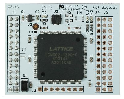
Contents
Quick Start                                           1
   Software Confidence Test                           1
Hardware                                              2
   Block Diagram                                      2
   Functional Description                             2
       Power                                          3
   Connectors                                         3
       J1 - 26-pin dual-row Raspberry Pi connector    3
       J2 - 26-pin dual-row expansion connector       4
       J3 - 8-pin single-row expansion connector      5
       J4 - 13-pin single-row expansion connector     5
       Test Points                                    6
   Dimensions                                         6
Firmware                                              7
   Directory Structure                                7
       Configuration                                  7
   flasher                                            8
   flashctl                                           8
   Simulating                                         9
   Compiling                                         10
Software                                             11
   Raspberry Pi Setup                                11
   Software Installation                             12
   Directory Structure                               12
   C/C++ shared library                              12
   Python Programs                                   12
   piffind.py                                        12
   pifload.py                                        13
   pifweb.py                                         13
Schematic                                            15
Legal Stuff                                          16
   The Design                                        16
Quick Start
Quick Start
This is the documentation for Bugblat's Raspberry Pi FPGA board - the pif board.
Your pif board comes with a small application already installed - it flashes the onboard LEDs in
antiphase.
So all you need to do is plug your pif board into your Pi and the LEDs should start doing what LEDs do
best.
Software Confidence Test
You can verify the software by flipping the pif board's configuration firmware from the flasher build,
where the LEDs light up in antiphase, to the flashctl configuration, where the LEDs light up in phase.
The Software page shows you how to enable I2C and SPI access on your Raspberry Pi, and how to
download the software.
Then change to the software directory and load the flashctl configuration. If you have a pif-1200, the
command line is:
sudo python pifload.py ../firmware/1200/flashctl/syn/pif_flashctl.jed
If you have a pif-7000, the command line is:
sudo python pifload.py ../firmware/7000/flashctl/syn/pif_flashctl.jed
1Hardware
Hardware
Block Diagram
Functional Description
The key components of the Bugblat pif board are
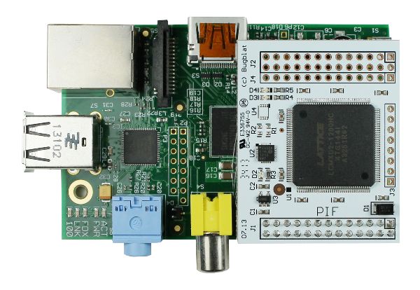
• XO2: a Lattice Semiconductor MachXO2 FPGA (details at Lattice)
• MCP23008: a Microchip I2C port expander (details at Microchip).
A pif-1200 uses an XO2-1200HC FPGA and a pif-7000 uses an XO2-7000HC FPGA. The 1200HC FPGA
contains 1280 four-input lookup tables (LUTs), the 7000HC FPGA contains 6864 LUTs. The 7000HC
part also has more on-chip memory and a second PLL. More LUTs means that a more complex design
can be fitted into the FPGA.
The MCP23008 is an 8-bit I/O expander that sits on the Raspberry Pi's I2C bus and drives the XO2's
control pins. The Raspberry Pi expansion bus does not have an abundance of pins, so it makes sense
to control low-activity pins in this way. The MCP23008 drives the following XO2 pins:
2Connectors
• JTAGENn. This pin lets your application use the XO2 JTAG port pins when it is high, reverting the
pins to JTAG usage when it is low.
• JTAG I/O, four pins.
• the FPGA PROGn, INITn, and DONE pins.
Pin Function Connection
9 GP0 FPGA pin 137, TDO
10 GP1 FPGA pin 136, TDI
11 GP2 FPGA pin 131, TCK
12 GP3 FPGA pin 130, TMS
13 GP4 FPGA pin 120, JTAGENn
14 GP5 FPGA pin 119, PROGn and test point TP1
15 GP6 FPGA pin 110, INITn
16 GP7 FPGA pin 109, DONE
Power
The XO2 runs at 3.3V, provided by an on-board regulator connected to the Raspberry Pi's 5V pins.
There is no connection to the Raspberry Pi's low-current 3.3V pins.
Regulated 3.3V is also routed to J2, but should only be used for minimal loads. For higher loads, the
raw 5V from the Raspberry Pi connector is fed out to J2 and you can use this to derive more current at
3.3V. But notice, and this is very important, that the pins on the XO2 can tolerate 3.3V only. XO2
I/O pins can not tolerate 5V.
So the standard hookup is this:
• 5V comes in from the Raspberry Pi
• an on-board regulator drops the 5V to 3.3V
• both the 5V and the 3.3V are fed to expansion connector pins
Connectors
J1 - 26-pin dual-row Raspberry Pi connector
Pin 1 is indicated by a square pad. As is standard, this connector has 13 rows, with two pins in each
row. The pins in the first row are numbered 1 and 2, the pins in the second row are numbered 3 and
4, and so on. This is different to the traditional numbering scheme for integrated circuits.
The I2C bus runs from the Raspberry Pi to the FPGA and the MCP23008, and also to matching pins on
J3. The I2C lines (SCL and SDA) are pulled up on the Raspberry Pi board. The FPGA can also be
configured to source a secondary I2C bus.
The SPI bus runs from the Raspberry Pi to the FPGA and to matching pins on J3. The Raspberry Pi
sources two SPI Slave Select signals. CE0 is connected to the FPGA Sn pin and is the SPI select signal
for configuration. CE1 is connected to FPGA pad 3 and is the SPI select signal for user logic.
Pin Definition
1 no connection
2 5V input from the Pi
3 I2C SDA - FPGA pin 125 and J2 pin 3.
4 5V input from the Pi
5 I2C SCL - FPGA pin 126 and J2 pin 5
3Connectors
6 Ground
7 Raspberry Pi clock - FPGA pin 128
8 GPIO14 - FPGA pin 32
9 Ground
10 GPIO15 - FPGA pin 27
11 GPIO17 - FPGA pin 25
12 GPIO18 - FPGA pin 23
13 GPIO27 - FPGA pin 20
14 Ground
15 GPIO22 - FPGA pin 19
16 GPIO23 - FPGA pin 13
17 no connection
18 GPIO24 - FPGA pin 11
19 SPI MOSI - FPGA pin 71 and J2 pin 19
20 Ground
21 SPI MISO - FPGA pin 45 and J2 pin 21
22 GPIO25 - FPGA pin 9
23 SPI SCK - FPGA pin 44 and J2 pin 23
24 SPI CE0 - FPGA pin 70
25 Ground
26 SPI CE1 - FPGA pin 3
J2 - 26-pin dual-row expansion connector
Pin 1 is indicated by a square pad. The pin numbering scheme is the same as for J1.
Pin Definition
1 3.3V output, 100mA maximum on the 3.3V pins together
2 5V output, from the Pi
3 I2C SDA - FPGA pin 125 and J1 pin 3
4 5V output, from the Pi
5 I2C SCL - FPGA pin 126 and J1 pin 5
6 Ground
7 XCLK - FPGA pin 34
8 XIO14 - FPGA pin 33
9 Ground
10 XIO15 - FPGA pin 28
11 XIO17 - FPGA pin 26
12 XIO18 - FPGA pin 24
13 XIO27 - FPGA pin 22
14 Ground
15 XIO22 - FPGA pin 21
4Connectors
16 XIO23 - FPGA pin 14
17 3.3V output, 100mA maximum on the 3.3V pins together
18 XIO24 - FPGA pin 12
19 SPI MOSI - FPGA pin 71 and J1 pin 19
20 Ground
21 SPI MISO - FPGA pin 45 and J1 pin 21
22 XIO25 - FPGA pin 10
23 SPI SCLK - FPGA pin 44 and J1 pin 23
24 XCE0 - FPGA pin 6
25 Ground
26 XCE1 - FPGA pin 4
J3 - 8-pin single-row expansion connector
Pin 1 is indicated by a square pad.
Pin Definition
1 FPGA pin 38
2 FPGA pin 42
3 FPGA pin 47
4 FPGA pin 49
5 Ground
6 FPGA pin 59
7 FPGA pin 61
8 FPGA pin 65
J4 - 13-pin single-row expansion connector
Pin 1 is indicated by a square pad.
Pin Definition
1 FPGA pin 74
2 FPGA pin 76
3 FPGA pin 82
4 FPGA pin 84
5 Ground
6 3.3V output, 100mA maximum on the 3.3V pins together
7 FPGA pin 92
8 FPGA pin 94
9 FPGA pin 98
10 FPGA pin 100
11 Ground
12 FPGA pin 105
13 FPGA pin 107
5Dimensions
Test Points
There is one test point on a pif board:
• TP1 is connected to GP5 on the MCP23008 and to PROGn on the FPGA (pin 119).
Dimensions
• Length: 48.3mm (1.9 inch)
• Width: 38.1mm (1.5 inch)
• Thickness: standard 1.6mm PCB, plus 1.3mm components, plus the Raspberry Pi connector
• Weight: almost nothing
6Firmware
Firmware
These example VHDL firmware programs are supplied with a pif board:
1. flasher.vhd is a simple program that alternately flashes the red and green LEDs.
2. flashctl.vhd also flashes the LEDs, but in this case the flash pattern can be controlled by an
external computer.
Directory Structure
• firmware
• 1200
• flasher
• flashctl
• 7000
• flasher
• flashctl
• common
There are separate directory trees for a pif-1200 and a pif-7000. With one exception (see the
Configuration section) HDL code is in the common directory.
It could be a useful precaution to hide or rename the directory for the board you do not have. For
instance, if you have a pif-1200, you could rename the 7000 directory to 7000x.
Configuration
Designs are configured for the XO2-1200HC and the XO2-7000HC FPGAs via the pifcfg package in
pifcfg.vhd files in the 1200 and 7000 directories. For example:
-- pifcfg.vhd, 1200 version
--
-- Initial entry: 01-Ju1-13 te
-- non-common definitions to personalise the pif implementations
--
-----------------------------------------------------------------------
library ieee; use ieee.std_logic_1164.all;
package pifcfg is
-- pif1200/7000 = 41h/42h = A/B
constant PIF_ID : std_logic_vector(7 downto 0) := x"41"; -- 'A'
constant XO2_DENSITY : string := "1200L";
end package pifcfg;
-----------------------------------------------------------------------
package body pifcfg is
end package body pifcfg;
Additional constants and functions can be added as a design requires. Usually the simplest practice is
to define a constant in pifcfg.vhd and use the constant to determine properties in a lower module. For
instance, a lower level module could include something like:
function myParameter(density: string) return integer is
begin
if density="1200L" then
return 1;
7flasher
else
return 3;
end if;
end;
Overall configuration definitions and useful constants are defined in the defs module pifdefs.vhd in
the common directory. A small snip of this file is:
library ieee; use ieee.std_logic_1164.all;
use ieee.numeric_std.all;
library work; use work.pifcfg.all;
package defs is
-- save lots of typing
subtype slv2 is std_logic_vector( 1 downto 0);
subtype slv3 is std_logic_vector( 2 downto 0);
subtype slv4 is std_logic_vector( 3 downto 0);
subtype slv5 is std_logic_vector( 4 downto 0);
subtype slv6 is std_logic_vector( 5 downto 0);
subtype slv7 is std_logic_vector( 6 downto 0);
subtype slv8 is std_logic_vector( 7 downto 0);
subtype slv16 is std_logic_vector(15 downto 0);
subtype slv32 is std_logic_vector(31 downto 0);
-------------------------------------------------------------
-- these constants are defined in outer 'pifcfg' files
constant ID : std_logic_vector(7 downto 0) := PIF_ID;
constant DEVICE_DENSITY : string := XO2_DENSITY;
-- I2C interface --------------------------------------------
constant A_ADDR : slv2 := "00";
constant D_ADDR : slv2 := "01";
constant I2C_TYPE_BITS : integer := 2;
constant I2C_DATA_BITS : integer := 6;
pif.lpf in the common directory is shared by all designs. In the main it defines the pinout of the FPGA.
flasher
flasher is a straightforward design. It uses the FPGA's built in oscillator to drive PWM patterns to the
on-board red and green LEDs. The LEDs are driven in antiphase.
The built in oscillator can be set to a variety of frequencies. We choose 26.6MHz, a frequency which is
useful in more complex designs.
flasher.vhd is a wrapper, the main work is done in piffla.vhd.
flashctl
flashctl is more complex than flasher - it can be controlled from the Raspberry Pi.
As before piffla.vhd generates antiphase LED pulses. However, the pulse stream fed to the FPGA I/Os
is controlled by a register that can be written to or read from via the I2C bus.
This is how it works. The i2c stream from the Raspberry Pi is wired up to a hard coded embedded
function block (EFB) in the FPGA.
The FPGA EFB implements:
• two i2c cores, a primary core and a secondary core
8Simulating
• one SPI core
• one 16-bit timer/counter
• an interface to on-chip flash memory which includes:
• user flash memory (UFM)
• configuration logic flash memory
• an interface to dynamic PLL settings
• an interface to the on-chip power controller
The EFB is exhaustively documented in the XO2 handbook which can be dowloaded from the Lattice
web site.
Our i2c stream is connected to the EFB's primary i2c core. The other side of the the EFB presents a
Wishbone interface to FPGA internal logic and that is the interface we use to control our logic.
The Wishbone interface is easily handled by a state machine, as seen in pifwb.vhd. This state
machine listens to events on the Wishbone interface, and generates a minimal internal address and
data bus. Here is the definition of the incoming address and data bus, extracted from pifdefs.vhd:
type XIrec is record -- write data for regs
PWr : boolean; -- registered single-clock write strobe
PRWA : TXA; -- registered incoming addr bus
PRdFinished : boolean; -- registered in clock PRDn goes off
PRdSubA : TXSubA; -- read sub-address
PD : TwrData; -- registered incoming data bus
end record XIrec;
pifctl.vhd listens to this bus, writes values into registers, and reads values from registers.
Here is an example of writing to a register on a pif board:
1. the Raspberry Pi executes an i2c write to send the data over i2c to the FPGA's EFB
2. the FPGA state machine detects data available on the Wishbone interface, reads in the data and
generates a write strobe
3. pifctl.vhd, or other application, logic detects the write strobe, checks for an address match, and
loads the data into an internal register
So where does the internal address come from? This design splits incoming bytes into a two bit type
field and a six bit data field. The type field can indicate an A byte or a D byte. If it is an A byte, the
data field is loaded into an address register, with the six bit field allowing up to 64 addresses. If it is a
D byte, the six bit data field and a write strobe go out over the internal data bus.
Reading from a register is simpler. Read data is always eight bits, there is no need for an address field
in readback data. The address register is loaded just the same as for a write. A read subaddress is
cleared to zero at the same time the address is written. The subaddress is incremented with every
read.
Assuming the address has already been loaded, here is an example of reading from a register on a pif
board:
1. the Raspberry Pi executes an i2c read of the FPGA's EFB
2. the FPGA state machine detects data required on the Wishbone interface. It writes the register
data to the wishbone interface, generates a read finished internal strobe, and increments the
subaddress
3. the Raspberry Pi picks up the data from i2c
Simulating
Most of the design time with HDLs is spent in a simulator. flashctl_tb in the common directory is a
simulation testbed.
9Compiling Compiling The Lattice Diamond system compiles HDL files to JEDEC bit streams. There are many paths for injecting the JEDEC data into a pif FPGA, but the documentation can be confusing. The official route is via the ispUFW and ispVM system. Since a pif board is a single chip system, we can use a simple solution - the Lattice Diamond JEDEC can be loaded directly into a pif FPGA via the pifload.py script. 10
Software

 Software
 The software supplied with a pif board supports

     • finding the pif board in your system
     • loading a configuration into the pif board
   • interacting with the pif board via a web/HTML front end
 Low level functions are supplied as C/C++ programs, high level functions are in Python.

 Raspberry Pi Setup
 Setting up your Raspberry Pi for GPIO access, I2C, and SPI is covered by many articles on the web so
 we will only give a brief summary for the Raspberry Pi Model B. Check on the net if you have a Model
 A.
 Provided you have /etc/modprobe.d/raspi-blacklist.conf, you will need to remove the I2C and SPI
 blacklisting. Start up an editor, for instance nano:
 sudo nano /etc/modprobe.d/raspi-blacklist.conf

 then comment out these lines by putting a # at the start of each line:
 blacklist spi-bcm2708
 blacklist i2c-bcm2708

 Add the I2C kernel modules by editing /etc/modules:
 sudo nano /etc/modules

 and insert two lines at the end of the file:
 i2c-bcm2708
 i2c-dev

 then reboot (sudo reboot).
 Download the i2ctools utility:
 sudo apt-get install python-smbus
 sudo apt-get install i2c-tools

 and check that the pi board is visible:
 sudo i2cdetect -y 1

 With the pif_flasher configuration loaded you should see this:
         0    1   2     3    4    5    6    7    8    9    a    b    c    d    e    f
 00:                   --   --   --   --   --   --   --   --   --   --   --   --   --
 10:   --    --   --   --   --   --   --   --   --   --   --   --   --   --   --   --
 20:   20    --   --   --   --   --   --   --   --   --   --   --   --   --   --   --
 30:   --    --   --   --   --   --   --   --   --   --   --   --   --   --   --   --
 40:   --    --   --   --   --   --   --   --   --   --   --   --   --   --   --   --
 50:   --    --   --   --   --   --   --   --   --   --   --   --   --   --   --   --
 60:   --    --   --   --   --   --   --   --   --   --   --   --   --   --   --   --
 70:   --    --   --   --   --   --   --   --

 And with the pif_flashctl configuration loaded you should see this:
         0    1   2     3    4    5    6    7    8    9    a    b    c    d    e    f
 00:                   --   --   --   --   --   --   --   --   --   --   --   --   --
 10:   --    --   --   --   --   --   --   --   --   --   --   --   --   --   --   --
 20:   20    --   --   --   --   --   --   --   --   --   --   --   --   --   --   --
 30:   --    --   --   --   --   --   --   --   --   --   --   --   --   --   --   --
 40:   40    41   --   43   --   --   --   --   --   --   --   --   --   --   --   --

11
Software Installation
50: -- -- -- -- -- -- -- -- -- -- -- -- -- -- -- --
60: -- -- -- -- -- -- -- -- -- -- -- -- -- -- -- --
70: -- -- -- -- -- -- -- --
20h is the I2C address for the pif's MCP23008, 40h is the XO2's I2C configuration address, 41h is the
XO2's I2C user-level slave address, and 43h is the XO2's I2C state machine reset address.
The standard pif software reloads the XO2 FPGA configuration flash via an SPI configuration port, but
the I2C configuration port is still active until it is explicitly disabled.
Software Installation
The software can be downloaded from http://www.bugblat.com/products/pif/pif.zip. Midori, the default
browser on Raspbian, will download to your home directory.
Alternatively you can download a Git repo: https://github.com/bugblat/pif
Directory Structure
• src
• static
• templates
C/C++ shared library
To control your pif board you need to
• access the Raspberry Pi SPI and I2C pins
• control the pif's onboard MCP23008
• control the pif's FPGA
To ease this task we provide shared library - libpif.so. libpif is written in C++, with a C wrapper so that
it can interface easily to scripting languages such as Python. The source files are in the src directory.
The interface is defined in the pifwrap.h file.
For SPI and I2C access on the Raspberry Pi, we use Mike McCauley's BCM2835 GPIO library.
To compile and install libpif.so you need to change to the software/src directory and enter the usual
recipe:
make
sudo make install
The software/src directory includes a precompiled libpif.so file - you can run the Python software even
if the compiler tools for C/C++ are missing from your system. You still need to run the install step
(sudo make install) if you use the precompiled libpif.so.
We use the ctypes package for the interface between libpif.so and Python scripts.
Python Programs
All the Python programs are provided as uncompiled files. Because they access SPI and I2C GPIO pins,
they must be run with root priviledges, most easily via the sudo command. For example:
sudo python piffind.py
piffind.py
This program scans the SPI bus. Here is the output from a run on my computer:
12pifload.py
================= pif find ========================
Using pif library version: 'libpif,Aug 2 2013,12:36:53'
XO2 Device ID: 012bd043 - device is an XO2-7000HC
==================== bye ==========================
pifload.py
This program takes a configuration JEDEC file as input. It then
1. searches for a pif board
2. clears the pif's FPGA flash memory
3. loads the new configuration data into the flash memory
4. reinitializes the FPGA.
For example, with this command line:
sudo python pifload.py pif_flasher.jed
this is the output from a run on my computer (the line starting programming has been shortened):
====================hello==========================
Configuration file is pif_flasher.jed
Using pif library version: 'libpif,Aug 2 2013,12:36:53'
XO2 Device ID: 012bd043 - device is an XO2-7000HC
XO2 Trace ID : 00.44.30.96_43.04.22.09
XO2 usercode from Flash: 00.00.00.00
XO2 usercode from SRAM : 50.49.46.30
JEDEC file is pif_flasher.jed
starting to read JEDEC file
first configuration data line: 23
. . . . . .
last configuration data line: 1591
1569 frames
finished reading JEDEC file
erasing configuration flash ... erased
programming configuration flash ... . . . . . . . . . . . . . . . programmed
transferring ...
configuration finished.
==================== bye ==========================
pifweb.py
This program implements browser control of the flashctl configuration in a pif board. You need to
have installed Aaron Swartz' web.py script:
sudo apt-get install python-webpy
There are several parts:
• pifweb.py uses web.py to
• start a web server
• serve up the application web page
• listen for GET and POST commands from the web page
• communicate with the pif board
• send replies to the web page
13pifload.py
• the content of the HTML that is generated is governed by index.html, layout.html, header.html,
and footer.html in the templates directory
• the appearance of the HTML is governed by style.css in the static directory
Make sure you have loaded the flashctl configuration in your pif board, for example via this command
line:
sudo python pifload.py pif_flashctl.jed
Start the program in a command window:
sudo python pifweb.py
Then point your browser at localhost:8080. This is what my browser shows:
14Schematic
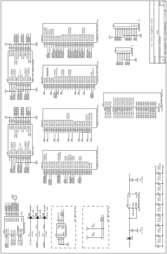
Schematic
Note that there are three Do Not Fit sites on the board:
• R1 and R2 will accept 0402 components and could be used for pullups to 3.3V. In normal usage,
these sites should not be populated - the Raspberry Pi provides I2C pullups.
• U4 will accept a DFN8 package, typically a CAT34C02 I2C EEPROM.
15Legal Stuff Legal Stuff This is a board for inquisitive minds with a basic understanding of electronics. You know what that means. Since the board is not a completed product it may not meet all the regulatory and safety compliance standards which may normally be associated with similar items. You assume full responsibility to determine and/or assure compliance with any such standards and related certifications as may be applicable. You will employ reasonable safeguards to ensure that your use of the the board will not result in any property damage or injury or death, even if the the board should fail to perform as described or expected. The Design The design materials referred to in this document are not supported and do not constitute a reference design. To the extent permitted by applicable law there is no warranty for the design materials. Except when otherwise stated in writing the copyright holders and/or other parties provide the design materials as is without warranty of any kind, either expressed or implied, including, but not limited to, the implied warranties of merchantability and fitness for a particular purpose. The entire risk as to the quality and performance of the design materials is with you. Should the design materials prove defective, you assume the cost of all necessary servicing, repair or correction. This board was designed as an evaluation and development tool. It was not designed with any other application in mind. As such, these design materials may or may not be suitable for any other purposes. If any design material is used it becomes your responsibility as to whether it meets your specific needs or the needs of your specific applications and the design material may require changes to meet your requirements. 16
You can also read