PIQ.3D-GATE FLEXIBLE OPTICAL 3D INSPECTION - AUTH: OLIVER ZIND - PRONES AUTOMATION GMBH
←
→
Page content transcription
If your browser does not render page correctly, please read the page content below
PIQ.3D-gate
Flexible Optical 3D Inspection

Auth:          Oliver Zind

Last edited:   June 2020
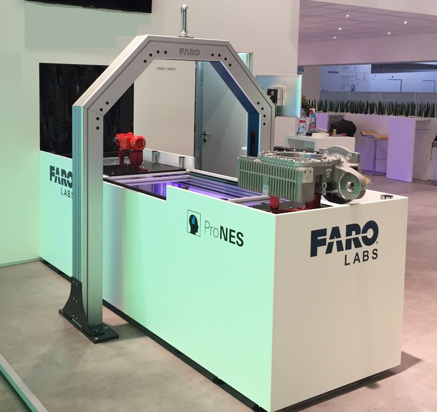
Table of contents

1     Task Definition .......................................................................... 3

1.2   Characteristics............................................................................ 3

2     Challenges ................................................................................ 4

2.1   Lot size 1 .................................................................................... 4

2.2   Complex surface structures ........................................................ 4

2.3   Flexible components ................................................................... 4

3     PIQ.3D-gate .............................................................................. 5

3.1   Capturing the specimen with leading-edge 3D sensors .............. 5

3.2   Use of special 3D evaluation software ......................................... 6

3.3   ProNES PIQ.3D-gate HMI........................................................... 8

4     PIQ.3D-gate – Design ............................................................. 10

4.1   PIQ.3D-gate with feeding by driverless transport systems......... 10

4.2   PIQ.3D-gate with feeding by a conveyor belt ............................ 11

4.3   PIQ.3D-gate with feeding by portal or robot handling ................ 11

5     Identification of Complex Characteristics ............................. 12

5.1   Task and background ............................................................... 12

5.2   Template Matching – basic idea ............................................... 14

5.3   Template Matching in combination with PIQ.3D-gate................ 15
      5.3.1 Procedure ..................................................................... 15

5.4   Test options for Template Matching .......................................... 16

                                                                                                          2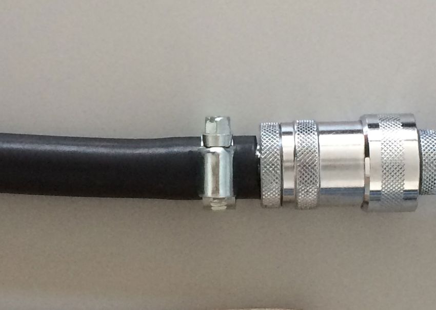
Task Definition

1     Task Definition
      The task that led to the development of the PIQ.3D-gate is the following:

      Entire optical inspection of products at the end of production for completeness
      and correct manufacturing

      This is not about dimensional accuracy of the products, but about ensuring and con-
      trolling a complete and correct assembly. In addition, these findings can be used to
      optimize production processes and derive complete documentation.
      With PIQ.3D-gate, manual checks and stand-alone image processing methods are
      replaced by fully automated and comprehensive quality assurance during the pro-
      duction process.

1.2   Characteristics
      Characteristics to be checked are, for example, the correct use of the individual com-
      ponents for assembling the product. Due to the many different product variants and
      the trend towards one-piece production, the risk of errors in assembly or incorrect
      component allocations increases.
      Conclusion: Ultimately, it must be ensured that all components have been selected
      completely and correctly, installed in the right place, in the right orientation and in
      perfect quality.

                                                                                           3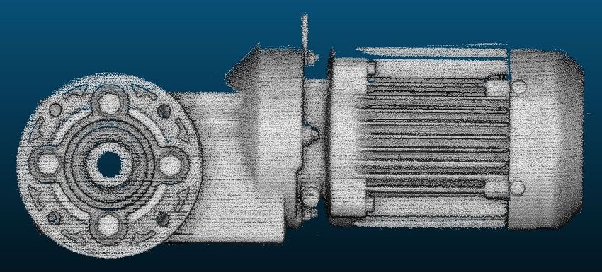
Challenges

2     Challenges
2.1   Lot size 1
      In many productions, there is no single production type, but there are rather many
      product variants with different test characteristics, that run through the same
      production line and / or the same test station.
      The challenge for the test systems is therefore to be able to adjust individually to each
      test specimen and to test the respective, specific characteristics individually.

2.2   Complex surface structures
      Due to new materials and production methods, the surface quality of the test speci-
      mens is a further challenge for quality assurance.
      Differences such as light, dark, matt or shiny surfaces represent a great challenge for
      any optical system.
      Furthermore, due to edges and corners, as with cooling fins, there is the danger that
      parts of the surface are shaded and lie outside the field of vision of the test system.
      Defects in shadow areas are therefore very difficult to detect with conventional sys-
      tems.

2.3   Flexible components
      If the test specimen has flexible components, such as cables, hoses, pipes, etc.,
      which do not run exactly at the same point on every test specimen, this represents a
      maximum challenge for every test system to test these flexible components and thus
      qualify the overall system.

                                                                                             4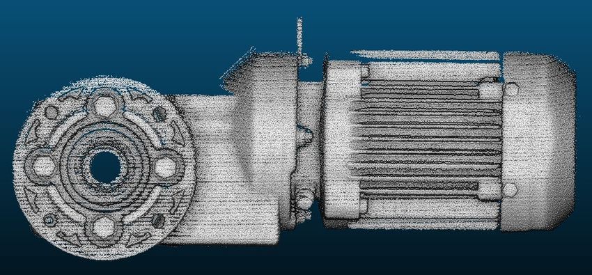
PIQ.3D-gate

3     PIQ.3D-gate
      In order to meet these maximum challenges, PIQ.3D-gate uses the latest innovative
      3D technology.

3.1   Capturing the specimen with leading-edge 3D sensors
      Leading-edge 3D scanners scan the entire surface of the test specimen in three di-
      mensions and generate a so-called 3D point cloud.
      This 3D point cloud corresponds exactly to the surface of the test specimen. All ex-
      ternally accessible components and features are included in their shape, position and
      diameter with highest precision.
      Thanks to the highly innovative technology of the 3D scanner used, even complex
      surfaces are precisely mapped in the 3D point cloud, regardless of their surface prop-
      erties.

               Fig. 1   Complex surfaces

                                                                                          5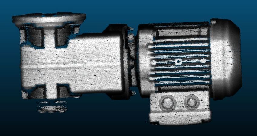
PIQ.3D-gate

3.2   Use of special 3D evaluation software
      Within the software environment, the generated point cloud is compared with a re-
      ference point cloud or a CAD model using special 3D evaluation algorithms.
      This allows both the product as a whole and individual components to be checked
      for correctness.

      Example: The wrong axis was installed in the motor on the right side.

      Fig. 2   Imperfection detection, example 1 – PIQ.3D-gate

      Deviations can be detected by comparing the captured point cloud against a refe-
      rence point cloud or a CAD model. These deviations are transferred to the integrated
      PIQ.3D-gate HMI application (Human-Machine-Interface) for further analysis, display
      and reporting, which assigns the deviations to certain characteristics and triggers
      further process steps, such as automatic sorting out of the faulty product.

                                                                                        6
PIQ.3D-gate

         Example: Two screws are missing from the right-hand hydraulic housing.

Fig. 3    Imperfection detection, example 2 – PIQ.3D-gate

                                                                                  7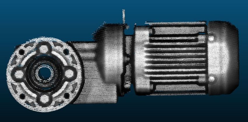
PIQ.3D-gate

3.3   ProNES PIQ.3D-gate HMI
      The ProNES PIQ.3D-gate HMI (Human Machine Interface) is the link between the
      operator, the production, the customer's infrastructure and the 3D inspection system.
      Due to the simple interface of the PIQ.3D-gate HMI, the machine operator does not
      need any in-depth 3D knowledge to operate the PIQ.3D-gate, since all 3D processes
      run fully automatically in the background and the results are displayed schematically
      in a simplified manner.

                               Fig. 4   GUI – PIQ.3D-gate

                                The ProNES PIQ.3D-gate HMI assigns the results deter-
                                mined in the background to the individual characteristics of
                                the test specimen and displays them in a simplified form
                                for the operator.

                                                                                          8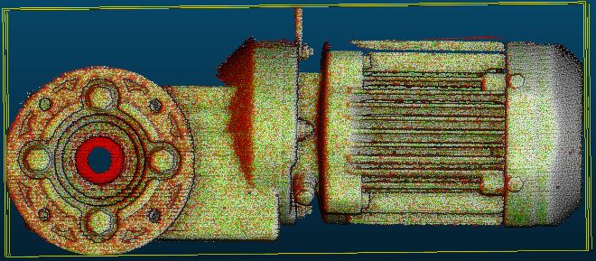
PIQ.3D-gate

By networking the PIQ.3D-gate HMI with the production infrastructure, it is possible
to incorporate direct feedback into the production process.

                        PIQ.3D-gate                                                    PIQ.3D-gate
                        (Location 1)                                                   (Location 2)

                                                                                                                                         Network
                                                                                                                                      Infrastructure

                                                              PIQ.
                                                                                                                          Firewall
                                                           dataserver

                                                                                                                                        Customer

                       Workstations Rework                                            Workstations Rework
                          (Location 1)                                                   (Location 2)

         Workstation       Workstation       Workstation                Workstation       Workstation       Workstation
          Rework            Rework            Rework                     Rework            Rework            Rework

                                                      Fig. 5             Networking –PIQ.3D-gate

If, for example, defects occur again and again at the same characteristic, this can be
reported directly to the corresponding assembly station so that production can react
immediately and avoid future defects.

Fig. 6    Overview – PIQ.3D-gate

The ProNES PIQ.3D-gate is not a stand-alone inspection system, but a quality as-
surance system fully integrated into the production process.

                                                                                                                                                       9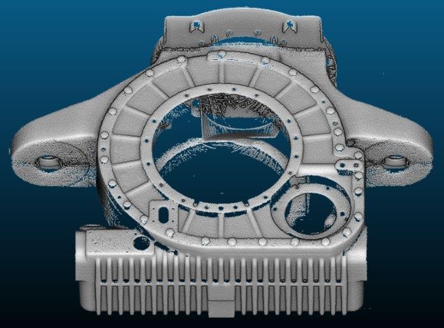
PIQ.3D-gate – Design
4 PIQ.3D-gate – Design
Depending on the production conditions and the requirements for the PIQ.3D-gate,
there are various implementation options.
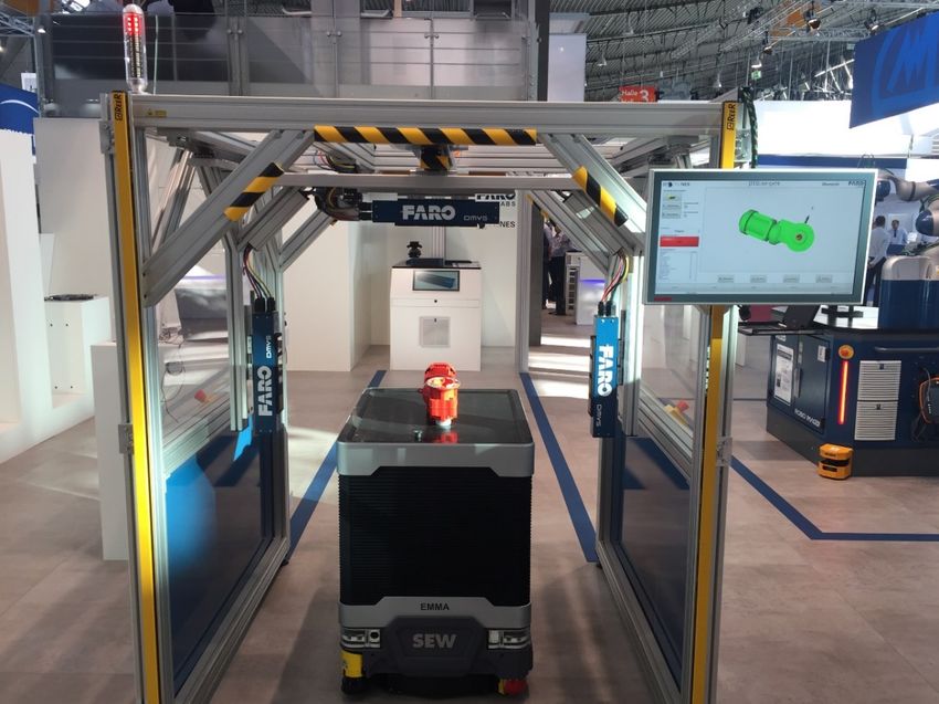
4.1 PIQ.3D-gate with feeding by driverless transport systems
1
Fig. 7 Inspection Cell – PIQ.3D-gate
The PIQ.3D-gate as an inspection cell is an ideal solution for production plants in
which products are moved using driverless transport systems, for example.
The test specimen is driven into the inspection cell with the driverless transport sys-
tem and stops there. With high-precision automation, the 3D sensors are moved over
the test object. At the same time, the sensors scan the entire surface.
Afterwards the result data are evaluated fully automatically and passed on to the pro-
cess control system.
10PIQ.3D-gate – Design
4.2 PIQ.3D-gate with feeding by a conveyor belt
Fig. 8 Conveyor belt in combination with PIQ.3D-gate
Alternately, the ProNES PIQ.3D-gate is also available for integration into transport
systems.
The specimen is moved through the gate, the sensors are statically integrated in the
PIQ.3D-gate. A major advantage of this variant is the reduced mechanical effort, e.g.
no moving components are required. Of course, this also results in significantly re-
duced safety requirements.
4.3 PIQ.3D-gate with feeding by portal or robot handling
This variant offers the highest possible flexibility in positioning the sensors in relation
to the component. Even test specimens with an extremely complex structure can
then be scanned and tested from all sides without any problems.
11Identification of Complex Characteristics
5 Identification of Complex Characteristics
5.1 Task and background
Many tasks involve testing flexible components such as cables, hoses, pipes, clamps,
etc. The special challenge here is that their position in relation to the test specimen is
never exactly the same and therefore a 1:1 image comparison is not possible.
In many cases, this is also not target-oriented, since there is often a certain tolerance
at which points the features or characteristics may be located, i.e. the position and
orientation of the features is flexible within certain limits.
In this context, the challenge for the test system is not to interpret the characteristic
as a simple image or as a simple point cloud. The focus is rather on detecting and
evaluating the characteristic itself – within certain tolerances independent of its posi-
tion – as a characteristic.
12Identification of Complex Characteristics
Example: The task is to check if there is a clamp on the hose and where the
clamp is fixed.
Clamp present: OK Clamp present: OK Clamp present: OK
Clamp position: nOK Clamp position: OK Clamp position: nOK
Fig. 9 Test scenarios
In order to solve the task successfully, several challenges have to be mastered:
Since the hose is flexible, its position and routing must be detected.
The position where the clamp should be located must be determined by loading
the correct template.
It must be checked whether the clamp is present and whether it is the correct
clamp.
The actual position of the clamp must be determined. It must also be checked
whether this position lies within the specified tolerance range.
The actual orientation of the clamp in relation to previously defined components
must be determined. It must also be checked whether the orientation lies within
the specified tolerance range.
13Identification of Complex Characteristics
5.2 Template Matching – basic idea
In Template Matching, the characteristic to be found is defined as a template that
needs to be present within a predefined space. The following illustration shows an
example template:
Fig. 10 Example template
This space can be defined depending on the characteristic in its size and position in
the CAD model: In the CAD model, you define a position at which the characteristic
is to be searched for. The search radius is defined by the predefined space.
Fig. 11 Search area in CAD model
14Identification of Complex Characteristics
If the template is found within the space, the characteristic or feature (for example,
the hose clamp) is present.
The position and orientation of the template in the space can also be used to check
whether the correct characteristic is present in the correct position and orientation.
5.3 Template Matching in combination with PIQ.3D-gate
The basic idea for using Template Matching with PIQ.3D-gate arose from the need
to be able to check complex characteristics.
At the same time, Template Matching offers customers the necessary system flexi-
bility to be able to define characteristics independently.
5.3.1 Procedure
All characteristics that are to be tested are listed in a checklist.
The type of characteristic is also defined in the checklist. For example, it is possi-
ble to create a flexible checklist for each individual variant of a unit to be tested.
For example, if the characteristics of a unit to be tested are divided into groups
according to variant, you can define for each unit to be tested which characteristic
is to be tested for the unit variant. The individual groups are then taught in before-
hand as templates. You can define individually for each unit to be tested which
characteristic from which group was used.
Before the test, the infrastructure transfers the test list of the test specimen to the
PIQ.3D-gate. The PIQ.3D-gate then decides on its own how the test and evalu-
ation must be carried out.
If a new characteristic or feature is to be taught in, the customer must sort this
into the existing groups or alternatively create a new group. A template of the
corresponding characteristic is read in and stored in the database of the PIQ.3D-
gate.
15Identification of Complex Characteristics
5.4 Test options for Template Matching
The Template Matching is very flexible and can be used for a wide range of charac-
teristics.
Some possible uses are listed below:
Teach in a single component such as a hose clamp as a template and check, for
example, whether the correct hose clamps are actually present at all points where
hose clamps should be present. In addition, it can be checked whether the posi-
tion of the hose clamp on the hose and its orientation in relation to the hose and
other components is correct.
Teach in complete assemblies as templates and check whether the correct as-
semblies are installed.
Check, which template corresponds to a component that is present at a certain
point. This is intended for cases in which different characteristics or assemblies
can be located at one position. For example, you can determine what type of
closure is located on an opening.
16You can also read