PLCM- LPT CNC USB controller - CONTENTS
←
→
Page content transcription
If your browser does not render page correctly, please read the page content below
www.purelogic.ru

Installation guide

PLCM- LPT
CNC USB controller

CONTENTS:
1. General information ......................................................... 2
2. Delivery set ....................................................................... 2
3. Technical specifications .................................................... 3
4. Basic sockets and indicators ............................................ 4
5. Installation and software setti .......................................... 5
2 revision 19.07.13 PLCM-LPT-2 CNC USB controller 3
3. TECHNICAL SPECIFICATIONS
Check wiki.purelogic.ru for more detailed information
! You can find common information about PLCM series controllers
in “User manual”
Supply voltage 5V from USB port
Maximum consumption current 150 mA
USB, Mini-USB socket type. STEP/
DIR/ENABLE signals translation,
Control interface input signals translation,
1. GENERAL INFORMATION compatibility with MACH3
STEP signals maximum frequency 100 kHz
This device is PLCM series controller (see “User manual”). It 5 pcs, buffered. Logical levels: “0”2.5V. Maximum input voltage: 15V
Its input-output port corresponds to PC LPT-port according to a
Quantity of outputs 12 pcs, buffered. 5V, 10 mA MAX
form and pins configuration.
Maximum quantity of CNC machine axes 6
Isolation resistance 500 MOhm
Operating temperature 0 … 50 °С
2. DELIVERY SET Net weight 0,1 kg
Overall dimensions (Width x Height x Depth) 70 x 20 x 55 mm
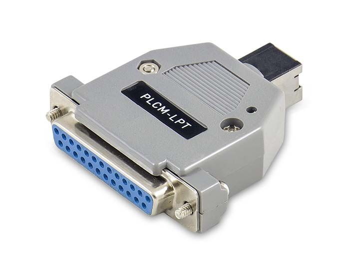
• PLCM-LPT controller – 1 pcs.
• User manual for PLCM series controllers – 1 pcs.
• Installation guide for PLCM-LPT – 1 pcs.
• Disk with the software – 1 pcs.
• USB cable, B type – 1 pcs. TURN OFF POWER DEVICE BEFORE MAKING ANY CONNECTIONS
• IDC26-DB25 (LPT) – 1 pcs. POWER SUPPLY NEGATIVE WIRE CONNECTION WITH GROUND
(GND), HOUSING AND ETC. IS FORBIDDEN
! HIGH-QUALITY SHIELDED CONNECTION CABLES IS RECOM-
MENDED TO USE
CONTROLLER WORKS WITH R3.043.xxx MACH3 VERSIONS AND
ABOVE, NECESSARILY UPDATE MACH3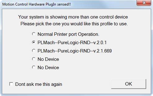
4 revision 19.07.13 PLCM-LPT-2 CNC USB controller 5
4. BASIC SOCKETS AND INDICATORS 5. INSTALLATION AND SOFTWARE SETTING
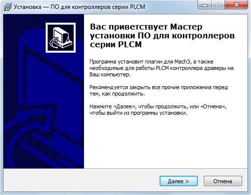
1. Connect controller to PC USB socket.
• XP1 socket is intended for PLCM-LPT connection to PC USB Windows operational system will suggest to install drivers for the
port. Connection is recommended to realize by a short shielded cable new device. Refuse their installation, it will be automatically executed
with ferrite rings for interference protection increase. on the following step.
• P1 port represents analog of PC LPT-port and has identical with 2. It is necessary to install PlugIn for device operation with MACH3.
it purpose and pins configuration: Download archive with PLCM series controllers software to the ad-
OUTPUTS – 1,2,3,4,5,6,7,8,9,14,16,17. dress www.purelogic.ru/files/downloads/SOFT/PLCM.zip and launch
INPUTS – 10,11,12,13,15. “setup.exe”. Controller Setup Wizard will open.
Fig. 2. Setup Wizard.
Lpt-port, DB-25F
XP1
P-1
«USB-B»
Fig.1. Diagram of sockets arrangement and indicators.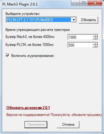
6                                                     revision 19.07.13     PLCM-LPT-2 CNC USB controller                                                 7

    Press “Next”. If you install software for the first time and you               3. Choose the corresponding PlugIn in a window presented at fig.
want that Setup Wizard install of necessary drivers, choose devices         4. when MACH3 runs after PlugIn installation.
which it is planned to apply on this PC (fig. 3). If any of devices isn’t           As a rule, in the list there are two PlugIn versions for PLCM con-
chosen, Setup Wizard will make only PlugIn updating for MACH3.              trollers: test and stable. Choose that with which you want to work at pre-
                                                                            sent. So that MACH3 doesn’t suggest to choose PlugIn in each launching
                                                                            it is necessary to place the tick «Don’t ask me again». If there is a need to
                                            Fig. 3. Driver installation.
                                                                            change the output device, select MACH3 menu item – Function Cfg’s – Re-
                                                                            set device sel.

                                                                                 * If you decided to pass to another version, for example, last time
                                                                                 you were working with stable version, and now you want to try test
                                                                                 version, after launching you NEED to follow in PlugIn settings (see
                                                                                 below) and to update the controller internal software.

                                                                                                                                 Fig. 4. PlugIn choice.

    Press “Next”, “Install”. Setup Wizard will copy necessary files
and will finish the work.

                                                                                4. After successful PlugIn launching in MACH3 PlugIn Control
                                                                            menu there will be a PLCM control item.
                                                                                Select this menu item.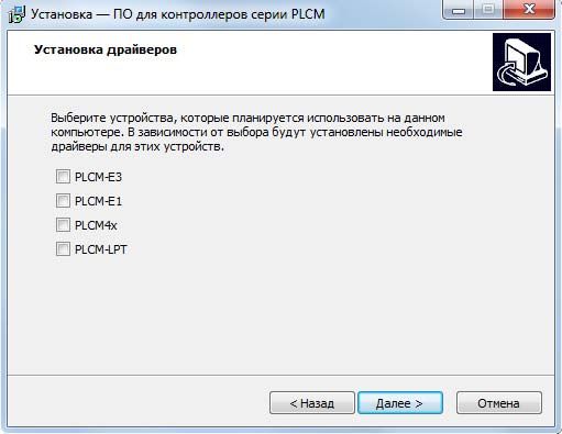
8                                                        revision 19.07.13       PLCM-LPT-2 CNC USB controller                                       9

     5. Execute PlugIn setting.                                                        Time of PLMACH look-ahead trajectory calculation - the sim-
     It is necessary to choose one of controllers connected to system            ilar buffer in PLCM board without MACH3 participating. The buffer
from the drop-down list. If PlugIn detects that the firmware became out-         stabilizes work during short-term failures of PLCMMACH3 con-
dated, it will be offered to update a firmware in the controller. It is enough   nection and decelerations of MACH calculation.
to make controller choice procedure once at the first device installation.             Remark: On the one hand the more value of these param-
                                                                                       eters, the better (it is more buffer, operation is stabler). But
                                           Fig. 5. PlugIn setting in MACH3             with buffer increase FeedHold will be delayed to the sum of
                                                                                       these two parameters, i.e. if MACH3 = 1 second buffer and
                                                                                       PLMach = 0.5 second buffer, CNC system reaction time will
                                                                                       be as the sum of FeedHold =1.5 second pressing and step
                                                                                       motor braking time according to the pre-set profile of accel-
                                                                                       eration.

                                                                                      The logging
                                                                                      In the logging process the log-file of PLCM< > MACH3 inter-
                                                                                 change is saved in file «C:\MACH3\PLСM.log». If the device op-
                                                                                 eration is incorrect this file needs to be sent to Purelogic RND
                                                                                 technical support service with the detailed problem description.

                                                                                      Press “OK” button for setting process completion.

      Settings description:
      Time of MACH3 look-ahead trajectory calculation - specifies the
data volume about a motion trajectory which the program needs to
prepare in advance, to count forward, it is a buffer. The more this
amount CNC operation is stabler. For example, MACH3 ceases to
count new trajectory data during rotation of ToolPath images. There-
fore the more those are counted in advance, motion «failure» prob-
ability is less during the image rotation or another load of MACH3.
!
Pay attention that documentation can be changed due
to constant technical upgrading of production.
You can download last versions from www.purelogic.ru
www.purelogic.ru
address: Bld. 160, Leninsky prospect,
Voronezh city, 394033, Russia
phone: +7 (495) 505-63-74,
+7 (473) 204-51-56
e-mail: info@purelogic.ruYou can also read