PORTABLE LED TIMER DISPLAY MANUAL - TI-2022
←
→
Page content transcription
If your browser does not render page correctly, please read the page content below
TI-2022
                             PORTABLE LED TIMER
                              DISPLAY MANUAL
                                    P1153
                                     ED-13736
                                      Rev 06
                                 13 December 2019

201 Daktronics Drive
Brookings, SD 57006-5128
www.daktronics.com/support
800.325.8766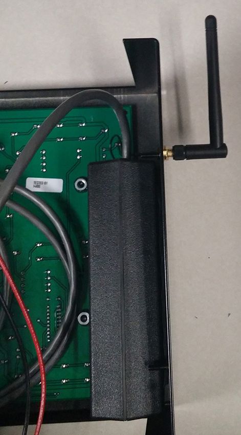
FCC Statement                                                Industry Canada Regulatory Information
Supplier Declaration of Conformity (SDoC)                    This Class A digital apparatus complies with Canadian
This product complies with Part 15 of the FCC Rules.         ICES-003.
Operation is subject to the following two conditions: (1)    Cet appareil numérique de la classe A est conforme à
This device may not cause harmful interference, and          la norme NMB-003 du Canada.
(2) this device must accept any interference received,
including interference that may cause undesired
operation.                                                   Inquiries
                                                             Contact Daktronics with any questions regarding our
Note: This equipment has been tested and found to            product compliance.
comply with the limits for a Class A digital device,
pursuant to part 15 of the FCC Rules. These limits are       Mail:
designed to provide reasonable protection against            Daktronics
harmful interference when the equipment is operated          201 Daktronics Dr.
in a commercial environment. This equipment                  Brookings, SD 57006 USA
generates, uses, and can radiate radio frequency
energy and, if not installed and used in accordance          Phone:
with the instruction manual, may cause harmful               800-325-8766
interference to radio communications. Operation of
this equipment in a residential area is likely to cause      Website:
harmful interference in which case the user will be          www.daktronics.com
required to correct the interference at their own
expense.

Warning: The user is cautioned that changes and
modifications made to the equipment without the
approval of manufacturer could void the user’s
authority to operate this equipment.

Copyright © 2003-2019
All rights reserved. While every precaution has been taken in the preparation of this manual, the publisher assumes no
responsibility for errors or omissions. No part of this book covered by the copyrights hereon may be reproduced or copied
in any form or by any means—graphic, electronic, or mechanical, including photocopying, taping, or information
storage and retrieval systems—without written permission of the publisher.
Daktronics trademarks are property of Daktronics, Inc. All other trademarks are property of their respective companies.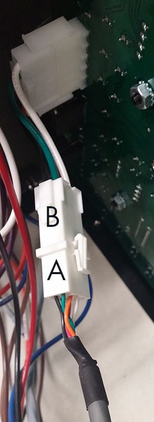
Table of Contents
1   Introduction���������������������������������������������������������������������������������������������������������������������������1
     Important Safety Instructions���������������������������������������������������������������������������������������������������������������1
     Specifications Label�����������������������������������������������������������������������������������������������������������������������������2
     Resources����������������������������������������������������������������������������������������������������������������������������������������������2
     Daktronics Nomenclature�������������������������������������������������������������������������������������������������������������������2
     Display Overview����������������������������������������������������������������������������������������������������������������������������������3
    Product Safety Approval���������������������������������������������������������������������������������������������������������������������3
2   Mechanical Installation�������������������������������������������������������������������������������������������������������4
     Wall Mounting���������������������������������������������������������������������������������������������������������������������������������������4
     Tripod Mounting������������������������������������������������������������������������������������������������������������������������������������5
3   Electrical Installation������������������������������������������������������������������������������������������������������������6
     Power�����������������������������������������������������������������������������������������������������������������������������������������������������6
       Auto Off���������������������������������������������������������������������������������������������������������������������������������������������6
    Wired Signal Connection���������������������������������������������������������������������������������������������������������������������7
    Wireless Signal Connection�����������������������������������������������������������������������������������������������������������������7
       Radio Settings�����������������������������������������������������������������������������������������������������������������������������������9
4   Controls & Timing Functions�����������������������������������������������������������������������������������������������10
     System Setup���������������������������������������������������������������������������������������������������������������������������������������10
     Program Selection������������������������������������������������������������������������������������������������������������������������������10
     Program Operations���������������������������������������������������������������������������������������������������������������������������11
5   Display Maintenance���������������������������������������������������������������������������������������������������������13
     Display Components��������������������������������������������������������������������������������������������������������������������������13
     Replacing the Digit/Driver Printed Circuit Board����������������������������������������������������������������������������14
     Replacing Batteries����������������������������������������������������������������������������������������������������������������������������14
     Schematics������������������������������������������������������������������������������������������������������������������������������������������15
     Replacement Parts�����������������������������������������������������������������������������������������������������������������������������15
6   Daktronics Exchange and Repair & Return Programs����������������������������������������������������16
     Exchange Program����������������������������������������������������������������������������������������������������������������������������16
     Repair & Return Program�������������������������������������������������������������������������������������������������������������������17
     Daktronics Warranty & Limitation of Liability�����������������������������������������������������������������������������������17
A Reference Drawings�����������������������������������������������������������������������������������������������������������19
B   Daktronics Warranty & Limitation of Liability��������������������������������������������������������������������23

                                                                            –i–
This page intentionally left blank.
1   Introduction
    This manual explains the installation and maintenance of Daktronics TI-2022 portable
    timing display. For additional information regarding safety, installation, operation, or
    service, refer to the telephone numbers listed in Section 6: Daktronics Exchange and
    Repair & Return Programs (p.16). This manual is not specific to a particular installation.
    Project-specific information takes precedence over general information found in this
    manual.

    Important Safety Instructions
    •   Read and understand all instructions before using the display.
    •   Do not drop the device or immerse it in water.
    •   This device may be used outdoors temporarily, but it is not to be permanently
        mounted outdoors or left in wet weather.
    •   This device shall not be exposed to dripping or splashing, and no objects filled with
        liquid shall be placed upon it.
        WARNING! To reduce the risk of fire or electric shock, do not expose this device to rain
        or moisture.
    •   Operate the device with the built-in rechargeable battery. A completely charged
        battery will provide at least 10 hours of operation. Use 120 V power only when the
        battery’s power is low.
        CAUTION! DANGER OF EXPLOSION IF BATTERY IS INCORRECTLY REPLACED.
        REPLACE ONLY WITH THE SAME OR EQUIVALENT TYPE.
        WARNING! Do not expose batteries to excessive heat, such as direct sunlight or open
        fire.
    •   Do not run the display’s battery dead. Charge it for 24 hours before putting it away.
    •   Do not let the power cord touch hot surfaces or hang over the edge of a table,
        which could damage or cut the cord.
    •   If an extension cord is necessary, use a three-pronged polarized cord. Arrange the
        cord with care so that no one will trip over or pull it out.
    •   Before using an extension cord, inspect the cable thoroughly and verify its
        compliance with the local electric codes.
    •   Always turn off and unplug the control equipment when it is not in use.
    •   Never yank the power cord to pull the plug from the outlet. Grasp the plug and pull
        to disconnect.
    •   To avoid electrical shock, do not disassemble the control equipment or the driver
        modules. Incorrect reassembly can cause electric shock and faulty operation or
        permanent damage to the circuits.
    WARNING! To prevent injury, the display must be securely attached to a wall in
    accordance with installation instructions.

                                       Introduction
                                             1
Specifications Label
Power specifications as well as serial and model number information can be found on an
ID label on the display, similar to the one shown in Figure 1.
THIS DEVICE COMPLIES WITH PART 15 OF THE FCC RULES. OPERATION IS SUBJECT TO
THE FOLLOWING TWO CONDITIONS: (1) THIS DEVICE MAY NOT CAUSE HARMFUL
INTERFERENCE AND (2) THIS DEVICE MUST ACCEPT ANY INTERFERENCE RECEIVED,
SUITABLE FOR SERVICING ONLY WHEN DE-ENERGIZED
INCLUDING INTERFERENCE THAT MAY CAUSE UNDESIRED OPERATION PUET FAIRE L'OBJET D'UN ENTRETIEN UNIQUEMENT S'IL EST HORS TENSION
DAKTRONICS 201 DAKTRONICS DR. BROOKINGS, SD PHONE 800-325-8766 LL-4284957
Figure 1: Specifications Label
Please have the assembly number, model number, and the date manufactured on hand
when calling Daktronics customer service to ensure the request is serviced as quickly as
possible. Knowing the facility name and/or job number will also be helpful.
Resources
Figure 2 illustrates a Daktronics drawing label.
This manual refers to drawings by listing the last
set of digits. In the example, the drawing would
be referred to as DWG-1007804. All references to
drawing numbers, appendices, figures, or other
manuals are presented in bold typeface. Drawing Number
Any drawings referenced in a section are listed Figure 2: Drawing Label
at the beginning of it as shown below:
Reference Drawing:
System Riser Diagram........................................................................................ DWG-1007804
Daktronics identifies manuals by the DD or ED number located on the cover page.
Daktronics Nomenclature
Most display components have a white label that lists the part 0P-1127-0024
number (Figure 3). Part numbers will also appear on certain drawings.
SN: 2465
If a component is not found in the Replacement Parts (p.15), use
02/19/12 Rev. 1
the label to order a replacement. Refer to Section 6: Daktronics
Exchange and Repair & Return Programs (p.16) if replacing or Figure 3: Part Label
repairing any display component.
Main Component Labels Accessory Labels
Part Type Part Number Component Label
Individual circuit board 0P-XXXX-XXXX Termination block for
TBXX
Assembly; a collection of power or signal cable
0A-XXXX-XXXX
circuit boards Grounding point EXX
Wire or cable W-XXXX Power or signal jack JXX
Fuse F-XXXX Power or signal plug for
PXX
Transformer T-XXXX the opposite jack
Metal part 0M-XXXXXXX
Fabricated metal assembly 0S-XXXXXX
Specially ordered part PR-XXXXX-X
Introduction
2Display Overview
The TI-2022 is a portable timing system with 9 programmable functions. Though external
power and signal can be applied, the control and power systems are entirely self-
contained. Refer to Section 4: Controls & Timing Functions (p.10) for descriptions of the
TI-2022 control capabilities.
Manufactured in two models, the outdoor version of the timing display is designated as
TI-2022-11, while the indoor unit is designated TI-2022-13.
The timing display is powered by 12 V batteries. Detachable power cord/transformer
assemblies also permit operation of the TI-2022 with 120 or 240 VAC. The unit draws 1
Amp of power. The enclosed batteries (two in the outdoor model and one in the indoor
model) are rechargeable and have a built-in charger.
Product Safety Approval
Both models of the TI-2022 are ETL-listed and tested to CSA standards for indoor use.
Contact Daktronics with any questions regarding the testing procedures.
Introduction
32 Mechanical Installation
This section describes the mounting details of the TI-2022. Use this section when mounting
a display to a wall or on the tripod kit. Other mounting methods can be used, but
Daktronics engineers do not recommend those not documented here. Daktronics is not
responsible for mounting the display.
Note: Daktronics assumes no liability for any installation derived from the information
provided in this manual or installations designed and installed by others.
Wall Mounting
The TI-2022 mounts to a wall using an optional mounting bracket (Daktronics part #
0M-173125). This bracket then attaches to two wall anchors. A qualified engineer must
specify the anchor type according to national and local building codes.
Note: Do not attempt to permanently suspend the TI-2022 by its carrying handle.
Also, do not permanently mount outdoor displays or leave in wet weather.
Before beginning installation, place the bracket against the mounting surface, level it,
and then mark the surface through the anchor holes on the bracket with a marker or
heavy pencil. Drill holes in the wall and install anchors at the marked locations. Minimum
steel anchor size is 3/16" diameter (4.7 mm).
Note: Due to the variety of wall materials used in sports facilities, Daktronics cannot
anticipate every user’s installation needs or provide mounting hardware suitable
for every installation. Choose a method of installation that will safely support the
display’s weight.
Refer to Figure 4 for display mounting instructions:
Wall Mounting Bracket
(0M-173125)
1. Mount the bracket to
the wall.
2. Loosen 4 screws on
sides of display, slip
them into slots on
bracket, and re-tighten.
Figure 4: Wall Mounting Kit Installation
Mechanical Installation
4Tripod Mounting
Mounting the display to a tripod requires the optional tripod mounting kit (Daktronics part
# 0A-1153-0325). A camera tripod is not sturdy enough to safely support the display and
will not attach to the display or adapter plate. An appropriate “speaker stand” tripod is
available from Daktronics (part # A-1580).
Refer to Figure 5 for instructions on preparing the display for mounting:
1. Remove rubber bumpers
from bottom of display.
Bumper (HE-1080)
Screw (HC-1489)
2. Push in and discard 2
bottom knockouts.
3. Attach tripod adapter plate
using bumpers and screws.
Tripod Adaptor Plate
(0S-1153-0036)
Bumper (HE-1080)
Screw (HC-1489)
Tripod Bracket
(HS-1306)
O-ring Nut
T-bolt
(HS-1315)
4. Install knob, nut, and washer Washer
on the tripod adaptor. Knob
5. Attach tripod bracket to adaptor
plate using O-rings and T-bolts.
Figure 5: Tripod Mounting Kit Installation
Mechanical Installation
53 Electrical Installation
Power
The TI-2022 contains internal batteries for power but can receive external power through
a detachable transformer cord (Figure 6).
Power Supply Kit:
12 V IN 120 VAC (0A-1240-0071)
240 VAC (0A-1240-0072)
120 or
240 VAC
Figure 6: Transformer Connection
The primary purpose of the transformer is to charge the internal battery, but the display
can still be operated while the battery is charging. The transformer and cord can remain
plugged into the power source indefinitely with no damage to the timer or its battery.
The indoor version (TI-2022-13) has one battery, while the outdoor version (TI-2022-11)
has two batteries. On a full charge, each battery should last approximately 10 hours
before recharge is necessary. To recharge the system, simply plug the power cable into
a grounded power receptacle. The recharging unit will not overcharge the batteries.
Indicator lights on the side control panel show when the unit is charging and when it is
fully charged (refer to Figure 11).
Auto Off
The TI-2022 features an Auto Off function, which will automatically turn the unit off in
response to two conditions:
1. Idle Timeout – If the display is not plugged into a transformer, and not in program
8 or 9 (time of day), and has been idle for 1 hour (not counting, no switch activity,
no signal input), the display will sound the horn and flash the digits 10 times before
turning itself off. Pressing any switch will reset the one hour timer.
2. Low Battery – This feature prevents the TI-2022 from running its battery completely
dead and damaging the battery. When the battery has dropped below a minimum
level, the unit will begin sounding the horn once per second as a warning. If the unit is
not plugged into the transformer for recharging within about one minute, the unit will
automatically turn off.
To turn the TI-2022 back on after an Auto Off has occurred, turn the power switch off,
wait a few minutes, and then turn it back on. In the case of a low battery, be sure to plug
the display into a charger before continuing use.
Electrical Installation
6Wired Signal Connection
The TI-2022 is designed as a standalone timer with no need for signal cable from control
consoles. However, it is still possible to connect signal in from Daktronics All Sport® scoring
consoles and OmniSport® 2000 timing consoles, and signal out to multiple displays. For
signal cable, Daktronics recommends, as a minimum, single-pair, shielded cable, 22
AWG (Daktronics part # W-1077). Two-pair shielded cable (part # W-1614) is preferred.
Wireless Signal Connection
The TI-2022 is capable of being controlled via wireless signal. The wireless radio system
requires a Daktronics All Sport® scoring console or OmniSport® 2000 timing console
equipped with radio transmitter as well as a radio receiver mounted inside the display.
The optional radio receiver is installed on the left side of the display cabinet (as viewed
from the front).
1. Power off the display.
2. Turn the display around so that you are looking at the rear.
3. Using a Phillips screwdriver, remove the 10 outer screws to separate the front and rear
panels of the display.
4. CAREFULLY lay the front panel flat to expose the internal components.
5. Connect the 6-pin power/signal cable from the radio receiver unit (A) into the mating
6-pin radio adapter cable (B) connected to the J2 RADIO JACK on the left side of the
driver printed circuit board (PCB). Refer to Figure 7.
Figure 7: Radio Connection
Electrical Installation
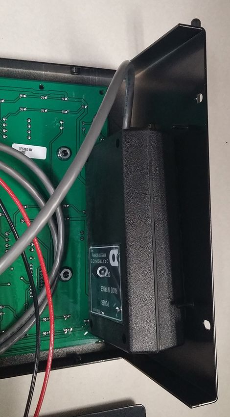
76. Remove the plastic strips from the adhesive-backed hook-and-loop fasteners on
the back of the radio receiver unit, and stick the unit to the inside right side of the
cabinet. Note that the radio receiver unit will be upside down. Refer to Figure 8.
Figure 8: Radio Mounting
7. Route the brass antenna connector through the “D” hole in the side of the display
cabinet. Slip on the washer and nut on the outside of the display, and then tighten
the nut using a 5/16 wrench. Screw the black antenna onto the brass connector.
Refer to Figure 9.
Figure 9: Radio Antenna
8. CAREFULLY close the front and rear panels. Ensure that no wires are pinched
between the metal panels.
9. Reinsert/tighten the 10 Phillips screws.
10. During operation, ensure the radio antenna stays pointed straight up.
For more information about the wireless radio control option, refer to the Gen VI Radio
Installation Manual (DD2362277), provided with the receiver unit and available online at
www.daktronics.com/manuals.
Electrical Installation
8Radio Settings
With a radio receiver installed in the display, watch for the radio Broadcast settings (“b1”)
and Channel settings (“C1”) during the Power-On Self Test (POST).
These values must match the settings in the control console:
RADIO SETTINGS
BCAST 1 CHAN 01
If the radio receiver channel and broadcast settings match those set in the console but
the console does not control the display, there may be radio interference. This can occur
when a nearby display also uses radio control. In this case, change the settings of the
wireless radio receiver inside the display and in the console as described in the radio
control manuals.
Electrical Installation
94 Controls & Timing Functions
System Setup
System setup information for each of the programs is shown in Figure 10. This chart is also
printed on a vinyl quick reference decal on the rear of the display case.
1 Count Up With Pushbuttons 2 Count Up With Photocells 3 Agility Timer
START START START
START START
STOP STOP
STOP STOP STOP
4 Game Clock 5 Qualifying Timer 6 Flop Clock
START START/STOP
7 Lap Counter
SIGNAL IN
8 9 Time Of Day
Optional All Sport
Control Console
Figure 10: TI-2022 Programs and System Connections
Program Selection
The TI-2022 display is programmable for 9 different timing START
DAKTRONICS
(INCREMENT HOURS)
programs. The operator selects each program and
makes settings for the functions using the switches on
the right side of the display. Figure 11 shows the TI-2022
control panel and programming connections. STOP
R
(INCREMENT MINUTES)
To select a program:
1. Press and hold for 2 seconds. The display will HORN
show PR## (program number) and then the preset (INCREMENT PROG. #)
TI-2022
time. SIGNAL IN
2. While holding , press and release
RESET
to increment the program number by one. Program (SHIFT)
numbers are as follows: SIGNAL OUT
1) Count Up w/ Pushbuttons
FULL
BATTERY
2) Count Up w/ Photocells LOW
CHARGE
STATUS 12V IN POWER
ON
3) Agility Timer AUX.
PORT
4) Game Clock OFF
5) Qualifying Timer
Figure 11: Control Panel
6) Flop Clock
7) Lap Counter
8) 12-hour Time of Day
9) 24-hour Time of Day
Note: Refer to Program Operations (p.11) for more information about each program.
Controls & Timing Functions
10To modify the preset time for programs 1, 2, 4, and 6:
1. Press and hold for 2 seconds. The display will show PR## (program number)
and then the preset time.
2. While holding , press to increment minutes and press to
increment seconds.
3. Release to save the time. The display will count up to or down from that time,
depending on the selected program.
To set the time of day for programs 8 and 9:
1. Press and hold for 2 seconds. The display will show PR## (program number)
and then the preset time.
2. While holding , press to increment hours and press to
increment minutes.
3. Release to save the Time of Day.
Program Operations
1. Count Up with Pushbuttons. This program counts up from 0 to a programmed time
and sounds the horn. Operators can program the time from 0 to 99:59 (mn:sc) using
the switches on the side of the display. If the time is set to 0:00, the display will count
up to 59:59, roll over to 0:00, and continue counting.
In this program, the time can be started and stopped using the switches on the side,
or external, normally open contacts. If a stop input is received within 9.99 seconds
before the start, the display will show a -XX.X time on the digits for 10 seconds
following the start and then will resume counting. While the display is counting, a start
input will hold the elapsed time for 10 seconds and then go back to the running time.
2. Count Up with Photocells. This program counts up from 0 to a programmed time and
sounds the horn. The operator can program the time from 0 to 99:59 (mn:sc) using the
switches on the side of the display. If the time is set to 0:00, the display will count up to
59:59, roll over to 0:00, and continue counting.
In this program, the start and stop inputs are typically external, normally closed
contacts. If the stop input is received within 9.99 seconds before the start, the display
will show a -X.XX time on the digits for 10 seconds following the start and then will
resume counting. While the display is counting, a start input will hold the elapsed time
for 10 seconds and then go back to the running time.
3. Agility Timer. This program is used to time events with a unique start and stop. These
events typically last less than 99.99 seconds; if the timer reaches 99.99, it will roll over
to 0.00 and continue counting. Unlike programs 1 and 2, once the timer is stopped, a
start input will not cause it to begin counting again.
4. Game Clock. This program counts down to 0 from a programmed time and sounds a
horn. The operator can program the time using the switches on the side of the display
from 0 to 99:59 (mn:sc). If the time is set to 0:00, the display will count down to 0:00,
roll over to 59:59, and continue counting down.
5. Qualifying Timer. This program utilizes one photocell plugged into the START input to
qualify oval track. Timing range is from 0 to 99.99 seconds.
Pressing the switch will set the display to 0.0 seconds and clear the best time.
With a photocell connected to the START input, the first car that passes through the
photocell will start the clock counting. The timer will then ignore the photocell for 3
seconds to ensure that the car has completely passed through the Start/Finish line.
Controls & Timing Functions
11The next time the car passes through the photocell, the clock will display the current
lap time for 10 seconds. Again, the clock will ignore the photocell for 3 seconds to
ensure that the car has passed completely through the Start/Finish line. The internal
clock also restarts at 0 and counts the time for the next lap. After the previous lap
has displayed for 10 seconds, the digits will show the new lap time. The next time a
car passes through the photocells, the time will freeze for 10 seconds and repeat the
cycle. This may be repeated for however many qualifying laps that a car will make.
When the car has completed its qualifying run, press the switch on the side
of the display, and the best lap time will be displayed on the digits. The qualifying
sequence for the next driver will start the next time a car passes through the
photocells.
6. Flop Clock. This mode counts up in one-second increments to 9999, rolls over to 0,
and continues counting.
7. Lap Counter. This program uses the switch to increment the display by one
from 1 to 9999. The switch decrements the count by one.
8. 12-Hour Time of Day. This program displays the time of day in 12-hour format.
9. 24-Hour Time of Day. This program displays the time of day in 24-hour format.
Note: An All Sport control console or an OmniSport timing console can be connected
to the TI-2022 to control it, but the TI-2022 system is then limited to being an output
device rather than the self-contained timing system for which it was designed.
Controls & Timing Functions
125 Display Maintenance
Disconnect power before doing any repair or maintenance work on the display.
Permit only qualified service personnel to access internal display electronics.
Disconnect power when not using the display.
Display Components
The TI-2022 uses a single printed circuit board (PCB) that contains all of the electronics
needed to make this system work: digit LEDs, control processors, power input connectors,
horn, and other components. All switches, power systems, and input/output terminations
are connected to the PCB.
As shown in Figure 12, the PCB is attached to the front panel of the display. Refer to
Replacing the Digit/Driver Printed Circuit Board (p.14) for instructions on accessing and
replacing the PCB.
8-32 Nut
Screw
(HC-1354)
(HC-1489)
Spacer
(HE-1357)
Battery
(BT-1014)
Rear
Panel
Printed Circuit Board
(Indoor: 0P-1153-0002)
0P-1153-0001)
Front Panel (Outdoor: 0P-1153-0004)
0P-1153-0003)
Nut securing
signal jack
Figure 12: TI-2022 Exploded View
Display Maintenance
13Replacing the Digit/Driver Printed Circuit Board
1. To access the digit/driver PCB, remove the 10 outer screws to separate the front and
back panels of the display.
2. Disconnect all plugs from the PCB by squeezing together the locking tabs and pulling
the connectors free. It may be helpful to label the cables or take a picture to know
which plug goes to which jack when connecting the replacement PCB.
3. Remove the 8 nuts securing the PCB to the front panel of the display. Take note of
the orientation of the PCB for future reference.
4. Carefully remove the PCB from the studs and spacers on the front panel. Use an even
force to prevent any damage that might result from bending the LEDs or connector
pins on the board.
5. Position the new PCB over the studs, making sure there are spacers between the front
panel and circuit board.
6. Tighten the 8 nuts.
7. Reconnect all plugs to their mating jacks on the PCB. The connectors are keyed and
will attach in one way only. Do not force the connections.
8. Close and secure the back panel with 10 screws, then power on and test the display
to verify the issue has been resolved.
Replacing Batteries
CAUTION! DANGER OF EXPLOSION IF BATTERY IS INCORRECTLY REPLACED. REPLACE ONLY
WITH THE SAME OR EQUIVALENT TYPE.
CAUTION: Do not allow any metal object, including jewelry, to contact the battery
terminal – a short-circuit on a battery can produce very high current, causing equipment
damage or severe burns!
To remove and replace a battery, refer to Figure 13 and follow these steps:
1. Remove the 10 outer screws to separate the front and back panels of the display.
2. Disconnect the power leads from the terminals.
3. Remove the 4 nuts securing the battery bracket.
4. Remove and replace the battery.
5. Reconnect the power leads to the terminals of the new battery exactly as follows:
RED to the POSITIVE terminal, BLACK to the NEGATIVE terminal.
6. Tighten the 4 nuts to secure the battery bracket.
7. Close and secure the back panel with 10 screws, then power on and test the display.
Do not throw old battery in trash. The battery contains lead and should be recycled.
WARNING! Do not expose batteries to excessive heat, such as direct sunlight or open fire.
Display Maintenance
14Bracket
Nut Terminals
IMPORTANT
CONNECT RED WIRE TO POSITIVE (+) TERMINAL.
CONNECT BLACK WIRE TO NEGATIVE (-) TERMINAL.
IF CONNECTED OTHERWISE, THE DISPLAY WILL NOT WORK PROPERLY AND MAY
DAMAGE COMPONENTS OR CAUSE INJURY.
Battery Bracket
(BT-1014)
Front View of Back Panel
Side View
(Indoor Model)
IMPORTANT
CONNECT RED WIRE TO POSITIVE (+) TERMINAL.
CONNECT BLACK WIRE TO NEGATIVE (-) TERMINAL.
IF CONNECTED OTHERWISE, THE DISPLAY WILL NOT WORK PROPERLY AND MAY
DAMAGE COMPONENTS OR CAUSE INJURY.
Front View of Back Panel
(Outdoor Model)
Figure 13: Battery Access
Schematics
For advanced troubleshooting and repair, it may be necessary to consult the schematic
drawing. DWG-177466 shows detailed power and signal wiring diagrams of internal
display components.
Replacement Parts
The following table contains display components that may require replacement. Many of
the other display components will have attached part number labels.
Description Part Number
Tripod Mounting Kit 0A-1153-0325
Power Supply Kit; 120VAC 0A-1240-0071
Power Supply Kit; 240VAC 0A-1240-0072
Wall Mounting Bracket 0M-173125
Indoor PCB 0P-1153-0002
Outdoor PCB 0P-1153-0004
Tripod, Speaker Stand Type A-1580
Battery, 12V 7.2 AH sealed lead-acid BT-1014
12 V Buzzer DS-1487
5-pin to 6-pin Radio Adapter W-2913
Refer to Section 6: Daktronics Exchange and Repair & Return Programs (p.16) for
information on exchanging or returning parts.
Display Maintenance
156 Daktronics Exchange and Repair & Return
Programs
Exchange Program
The Daktronics Exchange Program is a service for quickly replacing key components
in need of repair. If a component fails, Daktronics sends a replacement part to the
customer who, in turn, returns the failed component to Daktronics. This decreases
equipment downtime. Customers who follow the program guidelines explained below
will receive this service.
Before contacting Daktronics, identify these important numbers:
Display Serial Number: ________________________________________________________________
Display Model Number: _______________________________________________________________
Job/Contract Number: _______________________________________________________________
Date Manufactured/Installed: _________________________________________________________
Daktronics Customer ID Number: ______________________________________________________
To participate in the Exchange Program, follow these steps:
1. Call Daktronics Customer Service.
Market Description Customer Service Number
Schools (including community/junior colleges), religious 877-605-1115
organizations, municipal clubs, and community centers Fax: 605-697-4444
Universities and professional sporting events, live events for 866-343-6018
auditoriums, and arenas Fax: 605-697-4444
2. When the new exchange part is received, mail the old part to Daktronics.
If the replacement part fixes the problem, send in the problem part being replaced.
a. Package the old part in the same shipping materials in which the replacement
part arrived.
b. Fill out and attach the enclosed UPS shipping document.
c. Ship the part to Daktronics.
3. The defective or unused parts must be returned to Daktronics within 5 weeks of initial
order shipment.
If any part is not returned within five (5) weeks, a non-refundable invoice will be
presented to the customer for the costs of replenishing the exchange parts inventory
with a new part. Daktronics reserves the right to refuse parts that have been
damaged due to acts of nature or causes other than normal wear and tear.
Daktronics Exchange and Repair & Return Programs
16Repair & Return Program
For items not subject to exchange, Daktronics offers a Repair & Return Program. To send
a part for repair, follow these steps:
1. Call or fax Daktronics Customer Service.
Refer to the appropriate number in the chart on the previous page.
2. Receive a case number before shipping.
This expedites repair of the part.
3. Package and pad the item carefully to prevent damage during shipment.
Electronic components, such as printed circuit boards, should be placed in an
antistatic bag before boxing. Daktronics does not recommend using packing
peanuts when shipping.
4. Enclose:
• name
• address
• phone number
• the case number
• a clear description of symptoms
5. Ship to:
Daktronics Customer Service
[Case #]
201 Daktronics Drive, Dock E
Brookings, SD 57006
Daktronics Warranty & Limitation of Liability
The Daktronics Warranty & Limitation of Liability is located at the end of this manual.
The Warranty is independent of Extended Service agreements and is the authority in
matters of service, repair, and display operation.
Daktronics Exchange and Repair & Return Programs
17This page intentionally left blank.
A   Reference Drawings
    Refer to Resources (p.2) for information regarding how to read the drawing number.
    Any contract-specific drawings take precedence over the general drawings.
    Reference Drawings:
       Schematic; PC-2001 and TI-2022....................................................................... DWG-177466

                                         Reference Drawings
                                                 19
This page intentionally left blank.
This page intentionally left blank.
B   Daktronics Warranty & Limitation of Liability
    This section includes the Daktronics Warranty & Limitation of Liability statement (SL-02374).

                   Daktronics Warranty & Limitation of Liability
                                      23
This page intentionally left blank.
DAKTRONICS WARRANTY & LIMITATION OF LIABILITY
  This Warranty and Limitation of Liability (the “Warranty”) sets forth the warranty provided by Daktronics with respect to the
  Equipment. By accepting delivery of the Equipment, Purchaser and End User agree to be bound by and accept these terms and
  conditions. Unless otherwise defined herein, all terms within the Warranty shall have the same meaning and definition as
  provided elsewhere in the Agreement.

  DAKTRONICS WILL ONLY BE OBLIGATED TO HONOR THE WARRANTY SET FORTH IN THESE TERMS AND CONDITIONS UPON RECEIPT OF FULL
  PAYMENT FOR THE EQUIPMENT

  1.   Warranty Coverage.
            A.    Daktronics warrants to the original end user (the “End User”, which may also be the Purchaser) that the Equipment will be free
                  from Defects (as defined below) in materials and workmanship for a period of one (1) year (the “Warranty Period”). The
                  Warranty Period shall commence on the earlier of: (i) four weeks from the date that the Equipment leaves Daktronics’ facility;
                  or (ii) Substantial Completion as defined herein. The Warranty Period shall expire on the first anniversary of the commencement
                  date.
                  “Substantial Completion” means the operational availability of the Equipment to the End User in accordance with the
                  Equipment’s specifications, without regard to punch‐list items, or other non‐substantial items which do not affect the operation
                  of the Equipment
            B.    Daktronics’ obligation under this Warranty is limited to, at Daktronics’ option, replacing or repairing, any Equipment or part
                  thereof that is found by Daktronics not to conform to the Equipment’s specifications. Unless otherwise directed by Daktronics,
                  any defective part or component shall be returned to Daktronics for repair or replacement. This Warranty does not include on‐
                  site labor charges to remove or install these components. Daktronics may, at its option, provide on‐site warranty service.
                  Daktronics shall have a reasonable period of time to make such replacements or repairs and all labor associated therewith shall
                  be performed during regular working hours. Regular working hours are Monday through Friday between 8:00 a.m. and 5:00 p.m.
                  at the location where labor is performed, excluding any holidays observed by Daktronics.
            C.    Daktronics shall pay ground transportation charges for the return of any defective component of the Equipment. All such items
                  shall be shipped by End User DDP Daktronics designated facility. If returned Equipment is repaired or replaced under the terms
                  of this Warranty, Daktronics will prepay ground transportation charges back to End User and shall ship such items DDP End
                  User’s designated facility; otherwise, End User shall pay transportation charges to return the Equipment back to the End User
                  and such Equipment shall be shipped Ex Works Daktronics designated facility. All returns must be pre‐approved by Daktronics
                  before shipment. Daktronics shall not be obligated to pay freight for any unapproved return. End User shall pay any upgraded
                  or expedited transportation charges
            D.    Any replacement parts or Equipment will be new or serviceably used, comparable in function and performance to the original
                  part or Equipment and warranted for the remainder of the Warranty Period. Purchasing additional parts or Equipment from the
                  Seller does not extend the Warranty Period.
            E.    Defects shall be defined as follows. With regard to the Equipment (excepting LEDs), a “Defect” shall refer to a material variance
                  from the design specifications that prohibit the Equipment from operating for its intended use. With respect to LEDs, “Defects”
                  are defined as LED pixels that cease to emit light. Unless otherwise expressly provided, this Warranty does not impose any duty
                  or liability upon Daktronics for partial LED pixel degradation. Notwithstanding the foregoing, in no event does this Warranty
                  include LED pixel degradation caused by UV light. This Warranty does not provide for the replacement or installation of
                  communication methods including but not limited to, wire, fiber optic cable, conduit, trenching, or for the purpose of
                  overcoming local site interference radio equipment substitutions.

  EXCEPT AS OTHERWISE EXPRESSLY SET FORTH IN THIS WARRANTY, TO THE MAXIMUM EXTENT PERMITTED BY APPLICABLE LAW, DAKTRONICS
  DISCLAIMS ANY AND ALL OTHER PROMISES, REPRESENTATIONS AND WARRANTIES APPLICABLE TO THE EQUIPMENT AND REPLACES ALL OTHER
  WARRANTIES OR CONDITIONS, EXPRESS OR IMPLIED, INCLUDING, BUT NOT LIMITED TO, ANY IMPLIED WARRANTIES OR CONDITIONS OF
  MERCHANTABILITY, FITNESS FOR A PARTICULAR PURPOSE, OR ACCURACY OR QUALITY OF DATA. OTHER ORAL OR WRITTEN INFORMATION OR
  ADVICE GIVEN BY DAKTRONICS, ITS AGENTS OR EMPLOYEES, SHALL NOT CREATE A WARRANTY OR IN ANY WAY INCREASE THE SCOPE OF THIS
  LIMITED WARRANTY.
  THIS LIMITED WARRANTY IS NOT TRANSFERABLE.
  2.   Exclusion from Warranty Coverage
       This Warranty does not impose any duty or liability upon Daktronics for any:
            A.    damage occurring at any time, during shipment of Equipment unless otherwise provided for in the Agreement. When returning
                  Equipment to Daktronics for repair or replacement, End User assumes all risk of loss or damage, agrees to use any shipping
                  containers that might be provided by Daktronics, and to ship the Equipment in the manner prescribed by Daktronics;
            B.    damage caused by: (i)the improper handling, installation, adjustment, use, repair, or service of the Equipment, or (ii) any physical
                  damage which includes, but is not limited to, missing, broken, or cracked components resulting from non‐electrical causes;

  SL-02374 Rev 13 30 May 2019 Page 1 of 3
  Copyright © Daktronics, Inc.
DAKTRONICS WARRANTY & LIMITATION OF LIABILITY
altered, scratched, or fractured electronic traces; missing or gauged solder pads; cuts or clipped wires; crushed, cracked,
punctured, or bent circuit boards; or tampering with any electronic connections, provided that such damage is not caused by
personnel of Daktronics or its authorized repair agents;
C. damage caused by the failure to provide a continuously suitable environment, including, but not limited to: (i) neglect or misuse;
(ii) improper power including, without limitation, a failure or sudden surge of electrical power; (iii) improper air conditioning,
humidity control, or other environmental conditions outside of the Equipment’s technical specifications such as extreme
temperatures, corrosives and metallic pollutants; or (iv) any other cause other than ordinary use;
D. damage caused by fire, flood, earthquake, water, wind, lightning or other natural disaster, strike, inability to obtain materials or
utilities, war, terrorism, civil disturbance, or any other cause beyond Daktronics’ reasonable control;
E. failure to adjust, repair or replace any item of Equipment if it would be impractical for Daktronics personnel to do so because of
connection of the Equipment by mechanical or electrical means to another device not supplied by Daktronics, or the existence
of general environmental conditions at the site that pose a danger to Daktronics personnel;
F. statements made about the product by any salesperson, dealer, distributor or agent, unless such statements are in a written
document signed by an officer of Daktronics. Such statements as are not included in a signed writing do not constitute
warranties, shall not be relied upon by End User and are not part of the contract of sale;
G. damage arising from the use of Daktronics products in any application other than the commercial and industrial applications for
which they are intended, unless, upon request, such use is specifically approved in writing by Daktronics;
H. replenishment of spare parts. In the event the Equipment was purchased with a spare parts package, the parties acknowledge
and agree that the spare parts package is designed to exhaust over the life of the Equipment, and as such, the replenishment of
the spare parts package is not included in the scope of this Warranty;
I. security or functionality of the End User’s network or systems, or anti‐virus software updates;
J. performance of preventive maintenance;
K. third‐party systems and other ancillary equipment, including without limitation front‐end video control systems, audio systems,
video processors and players, HVAC equipment, batteries and LCD screens;
L. incorporation of accessories, attachments, software or other devices not furnished by Daktronics; or
M. paint or refinishing the Equipment or furnishing material for this purpose.
3. Limitation of Liability
A. Daktronics shall be under no obligation to furnish continued service under this Warranty if alterations are made to the
Equipment without the prior written approval of Daktronics.
B. It is specifically agreed that the price of the Equipment is based upon the following limitation of liability. In no event shall
Daktronics (including its subsidiaries, affiliates, officers, directors, employees, or agents) be liable for any claims asserting or
based on (a) loss of use of the facility or equipment; lost business, revenues, or profits; loss of goodwill; failure or increased cost
of operations; loss, damage or corruption of data; loss resulting from system or service failure, malfunction, incompatibility, or
breaches in system security; or (b) any special, consequential, incidental or exemplary damages arising out of or in any way
connected with the Equipment or otherwise, including but not limited to damages for lost profits, cost of substitute or
replacement equipment, down time, injury to property or any damages or sums paid to third parties, even if Daktronics has
been advised of the possibility of such damages. The foregoing limitation of liability shall apply whether any claim is based upon
principles of contract, tort or statutory duty, principles of indemnity or contribution, or otherwise
C. In no event shall Daktronics be liable for loss, damage, or injury of any kind or nature arising out of or in connection with this
Warranty in excess of the Purchase Price of the Equipment. The End User’s remedy in any dispute under this Warranty shall be
ultimately limited to the Purchase Price of the Equipment to the extent the Purchase Price has been paid.
4. Assignment of Rights
A. The Warranty contained herein extends only to the End User (which may be the Purchaser) of the Equipment and no attempt
to extend the Warranty to any subsequent user‐transferee of the Equipment shall be valid or enforceable without the express
written consent of Daktronics.
5. Governing Law; Election of Remedies
A. The rights and obligations of the parties under this Warranty shall not be governed by the provisions of the United Nations
Convention on Contracts for the International Sales of Goods of 1980. The parties consent to the application of the laws of the
State of South Dakota to govern, interpret, and enforce each of the parties’ rights, duties, and obligations arising from, or relating
in any manner to, the subject matter of this Warranty, without regard to conflict of law principles.
B. Any dispute, controversy or claim arising from or related to this Warranty, the parties shall first attempt to settle through
negotiations. In the event that no resolution is reached, then such dispute, controversy, or claim shall be resolved by final and
binding arbitration under the Rules of Arbitration of the International Chamber of Commerce. The language of the arbitration
SL‐02374 Rev 13 30 May 2019 Page 2 of 3
Copyright © Daktronics, Inc.DAKTRONICS WARRANTY & LIMITATION OF LIABILITY
shall be English. The place of the arbitration shall be Sioux Falls, SD. A single arbitrator selected by the parties shall preside over
the proceeding. If a single arbitrator cannot be agreed upon by the parties, each party shall select an arbitrator, and those
arbitrators shall confer and agree on the appointed arbitrator to adjudicate the arbitration. The arbitrator shall have the power
to grant any provisional or final remedy or relief that it deems appropriate, including conservatory measures and an award of
attorneys’ fees. The arbitrator shall make its decisions in accordance with applicable law. By agreeing to arbitration, the Parties
do not intend to deprive any court of its jurisdiction to issue a pre‐arbitral injunction, pre‐arbitral attachment, or other order in
aid of arbitration proceedings and the enforcement of any award. Without prejudice to such provisional remedies as may be
available under the jurisdiction of a court, the arbitrator shall have full authority to grant provisional remedies and to direct the
Parties to request that any court modify or vacate any temporary or preliminary relief issued by such court, and to award
damages for the failure of any Party to respect the arbitrator’s orders to that effect.
6. Availability of Extended Service Agreement
A. For End User’s protection, in addition to that afforded by the warranties set forth herein, End User may purchase extended
warranty services to cover the Equipment. The Extended Service Agreement, available from Daktronics, provides for electronic
parts repair and/or on‐site labor for an extended period from the date of expiration of this warranty. Alternatively, an Extended
Service Agreement may be purchased in conjunction with this Warranty for extended additional services. For further
information, contact Daktronics Customer Service at 1‐800‐DAKTRONics (1‐800‐325‐8766).
Additional Terms applicable to sales outside of the United States
The following additional terms apply only where the installation site of the Equipment is located outside of the United States of America.
1. In the event that the installation site of the Equipment is in a country other than the U.S.A., then, notwithstanding Section 5 of the Warranty,
where the selling entity is the entity listed in Column 1, then the governing law of this Warranty is the law of the jurisdiction listed in the
corresponding row in Column 2 without regard to its conflict of law principles. Furthermore, if the selling entity is an entity listed in Column
1, then the place of arbitration is listed in the corresponding row in Column 3.
Column 1 Column 2 Column 3
(Selling Entity) (Governing Law) (Location of Arbitration)
Daktronics, Inc. The state of Illinois Chicago, IL, U.S.A.
Daktronics Canada, Inc. The Province of Ontario, Canada Toronto, Ontario, Canada
Daktronics UK Ltd. England and Wales Bristol, UK
Daktronics GmbH The Federal Republic of Germany Wiesbaden, Germany
Daktronics Hong Kong Limited Hong Kong, Special Administrative Region of the P.R.C. Hong Kong SAR
Daktronics Shanghai Co., Ltd. The Peoples Republic of China Shanghai, P.R.C.
Daktronics France, SARL France Paris, France
Daktronics Japan, Inc. Japan Tokyo, Japan
Daktronics International Limited Macau, Special Administrative Region of the P.R.C. Macau SAR
Daktronics Australia Pad Ltd Australia Sydney, Australia
Daktronics Singapore Pte. Ltd Singapore Singapore
Daktronics Brazil LTDA Brazil São Paulo, Brazil
Daktronics Spain S.L.U. Spain Madrid, Spain
Daktronics Belgium N. V Belgium Kruibeke, Belgium
Daktronics Ireland Co. Ltd. Ireland Dublin, Ireland
SL‐02374 Rev 13 30 May 2019 Page 3 of 3
Copyright © Daktronics, Inc.This page intentionally left blank.
You can also read