Dell EMC PowerSwitch S6100-ON Installation Guide - March 2021
←
→
Page content transcription
If your browser does not render page correctly, please read the page content below
Dell EMC PowerSwitch S6100-ON
Installation Guide
March 2021

March 2021
Rev. A08
Notes, cautions, and warnings

     NOTE: A NOTE indicates important information that helps you make better use of your computer.

     CAUTION: A CAUTION indicates either potential damage to hardware or loss of data and tells you how to avoid
     the problem.

     WARNING: A WARNING indicates a potential for property damage, personal injury, or death.

© 2015 - 2021 Dell Inc. or its subsidiaries. All rights reserved. Dell, EMC, and other trademarks are trademarks of Dell Inc. or its subsidiaries.
Other trademarks may be trademarks of their respective owners.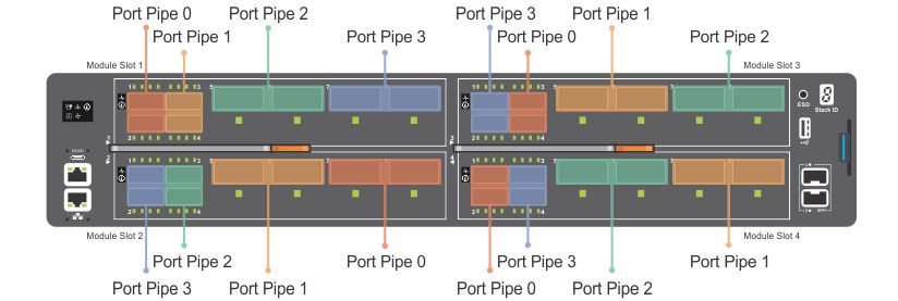
Contents

Chapter 1: About this guide........................................................................................................... 5
  Notices................................................................................................................................................................................... 5
  Related documents............................................................................................................................................................. 5

Chapter 2: S6100–ON system........................................................................................................6
  Introduction...........................................................................................................................................................................6
  Features................................................................................................................................................................................. 7
  Physical dimensions.............................................................................................................................................................8
  Luggage tag.......................................................................................................................................................................... 8
  System status.......................................................................................................................................................................9
  LED display............................................................................................................................................................................ 9
      LED behavior ................................................................................................................................................................. 9
  Prerequisites........................................................................................................................................................................ 11
  S6100–ON configurations................................................................................................................................................ 11

Chapter 3: Site preparations........................................................................................................ 12
  Site selection.......................................................................................................................................................................12
  Cabinet placement............................................................................................................................................................. 12
  Rack mounting.................................................................................................................................................................... 13
  System ground....................................................................................................................................................................13
  Fans and airflow................................................................................................................................................................. 13
  Power....................................................................................................................................................................................13
  Storing components.......................................................................................................................................................... 13

Chapter 4: NEBS compliance....................................................................................................... 15
  Important information....................................................................................................................................................... 15
  NEBS-compliant ground installation..............................................................................................................................15
     For rack spans from 22 to 23.375 inches...............................................................................................................16
     For rack spans from 23.375 to 36 inches...............................................................................................................18

Chapter 5: S6100–ON installation................................................................................................ 21
  Installation overview..........................................................................................................................................................21
  Unpack the S6100-ON System.......................................................................................................................................21
  Four-post rack assembly................................................................................................................................................. 22
  Four-post rack mount...................................................................................................................................................... 22
  Chassis ground...................................................................................................................................................................23
  I/O module installation..................................................................................................................................................... 25
     Important points.......................................................................................................................................................... 25
  SFP+ and QSFP optics installation............................................................................................................................... 26
  SFP+ and QSFP optics removal.................................................................................................................................... 26
  Port connectivity...............................................................................................................................................................26
  System power-up.............................................................................................................................................................. 28

Chapter 6: Power supplies...........................................................................................................29

                                                                                                                                                                Contents                   3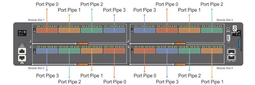
Components....................................................................................................................................................................... 29
         AC or DC power supply installation.............................................................................................................................. 30
           DC power supply connection.....................................................................................................................................31
         AC or DC power supply replacement........................................................................................................................... 32

    Chapter 7: Fans........................................................................................................................... 33
      Components....................................................................................................................................................................... 33
      Fan module installation.....................................................................................................................................................34
      Fan module replacement................................................................................................................................................. 34
      Fan air filter replacement................................................................................................................................................ 35
      After system installation..................................................................................................................................................35

    Chapter 8: Management ports..................................................................................................... 36
      RS-232 console port access...........................................................................................................................................36
         Accessing the RJ-45 Console Port with a DB-9 Adapter..................................................................................37
      Micro USB-B console port access................................................................................................................................ 37
      USB storage........................................................................................................................................................................37
      Before you install an OS.................................................................................................................................................. 38
      ONIE service discovery....................................................................................................................................................39

    Chapter 9: Dell support................................................................................................................41

    Chapter 10: Specifications...........................................................................................................43
      Chassis physical design....................................................................................................................................................43
      IEEE standards................................................................................................................................................................... 44
      Agency compliance........................................................................................................................................................... 45
      USA Federal Communications Commission (FCC) statement............................................................................... 45
      European Union EMC Directive Conformance statement.......................................................................................45
      Japan: VCCI Compliance for Class A Equipment.......................................................................................................46
      Korean Certification of Compliance..............................................................................................................................46
      Safety Standards and Compliance Agency Certifications....................................................................................... 47
      Electromagnetic Compatibility (EMC)..........................................................................................................................47
      Product recycling and disposal...................................................................................................................................... 48

4   Contents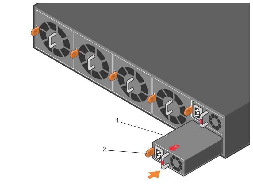
1
                                                                                  About this guide
This guide provides site preparation recommendations, step-by-step procedures for rack mounting and desk mounting, inserting
optional modules, and connecting to a power source.
Topics:
•   Notices
•   Related documents

Notices
    CAUTION: To avoid electrostatic discharge (ESD) damage, wear grounding wrist straps when handling this
    equipment.

    NOTE: Only trained and qualified personnel can install this equipment. Read this guide before you install and power up this
    equipment. This equipment contains two power cords. Disconnect both power cords before servicing.

    NOTE: This equipment contains optical transceivers, which comply with the limits of Class 1 laser radiation.

    Figure 1. Class 1 Laser Product Tag

    NOTE: When no cable is connected, visible and invisible laser radiation may be emitted from the aperture of the optical
    transceiver ports. Avoid exposure to laser radiation and do not stare into open apertures.

Related documents
For more information about the S6100–ON system, see the following documents:
● Dell Getting Started Guide for the S6100–ON System
● Dell Release Notes for the S6100–ON System
● Open Networking (ON) Hardware Diagnostic Guide
● Dell Command Line Reference Guide for the S6100–ON System
● Dell Configuration Guide for the S6100–ON System
    NOTE: For the most recent documentation, visit Dell Support: www.dell.com/support.

                                                                                                      About this guide            5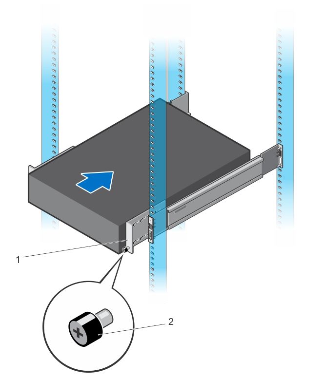
2
                                                                             S6100–ON system
The following sections describe the Dell S6100–ON system:
Topics:
•   Introduction
•   Features
•   Physical dimensions
•   Luggage tag
•   System status
•   LED display
•   Prerequisites
•   S6100–ON configurations

Introduction
S6100-ON is a two rack unit 10/25/40/100 GbE switch. A fully loaded system includes 64 quad form-factor pluggable (QSFP+
or QSFP28) optics for 40/100 GbE aggregation and 10/25/40/100 GbE top of rack (ToR) and end of row (EoR) applications.
The S6100–ON system includes two hot-swappable AC or DC power supply units (PSUs) and four hot-swappable fan units.
The S6100–ON supports three types of I/O modules:
● 16 x 40 GbE QSFP+
  ○ Top row of ports can operate as:
      ■ Single 40G port
      ■ Quad 10G ports
              NOTE: If you configure port [n] as a quad 10G port, port [n + 1] will not be available
● 8 x 100 GbE QSFP28
  ○ Each port can operate as:
      ■ Single 100G port
      ■ Single 40G port
      ■ Quad 25G ports
      ■ Quad 10G ports
● 4 x QSFP28 + 4 x CXP
  ○ Each QSFP28 port can operate as:
      ■ Single 100G port
      ■ Single 40G port
      ■ Quad 25G ports
      ■ Quad 10G ports
  ○ Each CXP port can operate as:
      ■ Single 100G port
All 100 GbE (QSFP28) ports support 4 x 25 GbE.

6       S6100–ON system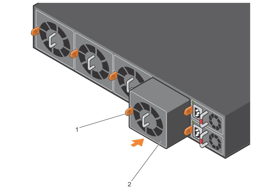
Figure 2. S6100–ON I/O-side view
1. MicroUSB-B port                                        2. 64 x 10/40 QSFP+ or 32 x 10/25/40/100 QSFP28
3. USB Type A                                             4. SFP+ ports
5. Top: RJ-45 console port. Bottom: RJ-45 management port

Figure 3. S6100–ON PSU-side view
1. Fan modules
2. Power supply units

Features
The S6100–ON offers the following features:
●   Up to four I/O modules of 8 x 10/25/40/50/100 GbE QSFP28 ports
●   Up to four I/O modules of 16 x 10/40 GbE QSFP+ ports
●   Up to four I/O modules of 4 x 10/25/40/50/100 GbE QSFP28 ports and 4 x 100 GbE CXP ports
●   Up to one hundred twenty-eight 10G ports
●   Up to one hundred twenty-eight 25G ports
●   Up to sixty-four 40G ports
●   Up to sixty-four 50G ports
●   Up to thirty-two 100G ports
●   Two SFP+ ports
●   One micro universal serial bus (MicroUSB-B) console port, optional
●   One 2.0 USB Type-A port for additional file storage
●   One 10/100/1000BaseT Ethernet management port
●   Rangeley central processing unit (CPU) system with 8GB DDR III RAM.
●   Temperature monitoring
●   Software-readable thermal monitor
●   Real time clock (RTC) support
●   Hot-pluggable redundant power supplies
●   Power management monitoring
●   Four hot-pluggable replaceable fan modules

                                                                                               S6100–ON system   7
● Standard 2U chassis
● Two-hole ground lug

Physical dimensions
The S6100-ON has the following physical dimensions:
● 442 x 510 x 86.75 mm (W x D x H)
● 17.40 x 20 x 3.41 inches (W x D x H)

Luggage tag
The S6100–ON system has a pull-out tag, known as a luggage tag, on the I/O-side of the system.

Figure 4. S6100–ON luggage tag
1. Service tag                                               2. PPID
3. MAC address                                               4. Express service code

8       S6100–ON system
System status
You can view S6100–ON status information using the LEDs.

LED display
The S6100–ON includes LED displays on the I/O side of the system.
     NOTE: If you are installing third-party software, for LED information, see your third-party operating software
     documentation.

LED behavior
The following S6100–ON system LED behavior is seen during open networking installation environment (ONIE) operations:

Figure 5. S6100–ON LEDs
1.   Fan LED                                                     2.    Power LED
3.   Master LED                                                  4.    System LED
5.   Locator LED                                                 6.    Locator LED
7.   System LED                                                  8.    Port LEDs
9.   Stack ID LED                                                10.   RJ-45 Ethernet Management Port LED

Table 1. S6100–ON LED behavior
LED                                                               Description
System Status and Health LED                                      ●    Off—No power
                                                                  ●    Solid green—Normal Operation
                                                                  ●    Blinking green—POST is in process
                                                                  ●    Solid amber—Critical system error
                                                                  ●    Blinking amber—Minor system error
Power LED                                                         ●    Off—No power
                                                                  ●    Solid green—Normal Operation
                                                                  ●    Solid amber—POST is in process
                                                                  ●    Blinking amber—Noncritical system error—power supply
                                                                       failure

                                                                                                     S6100–ON system          9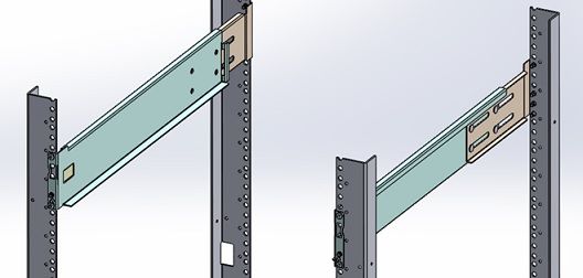
Table 1. S6100–ON LED behavior (continued)
LED                                            Description
Master LED                                     ● Off—Switch is in Stacking Slave mode
                                               ● Solid green—System is in Stacking Master or Standalone
                                                 mode
Management LED                                 ●   Off—No Link
                                               ●   Solid green—Link on 1 Gbps speed
                                               ●   Solid amber—Link on 10/100 Mbps speeds
                                               ●   Blinking green—Port activity
FAN LED                                        ● Off—No power
                                               ● Solid green—fan powered and running at the expected
                                                 RPM
                                               ● Blinking amber—fan failed, including incompatible airflow
                                                 direction when you insert the PSU or fan trays with
                                                 differing airflows
LOCATOR LED                                    ● Off—Locator is idle
                                               ● Blinking blue—Locator is functioning

Table 2. QSFP28 port LEDs
LED                                            Description
Link LED                                       ● Off—No Link
                                               ● Solid green—Port activity operating at maximum port
                                                 speed
                                               ● Solid amber—Port activity operating at lower speed
Activity LED                                   ● Off—No Link
                                               ● Flashing green, ~30 ms—port activity operating at
                                                 maximum port speed
                                               ● Flashing amber, ~30 ms—port activity operating at lower
                                                 port speed

Table 3. QSFP28 port LEDs—4x25 GbE or 4x10 GbE Mode
LED                                            Description
Link LED                                       ● Off—No Link
                                               ● Solid green—Port link is 4x25 GbE
                                               ● Solid amber—Port link is 4x10 GbE
Activity LED                                   ● Off—No Link
                                               ● Flashing green, ~30 ms—Port link is 4x25 GbE
                                               ● Flashing amber, ~30 ms—Port link is 4x10 GbE

Table 4. QSFP28 Port LEDs—2x40GbE Mode
LED                                            Description
Link LED                                       ● Off—No Link
                                               ● Solid green—Port link is 2x40 GbE
Activity LED                                   ● Off—No Link
                                               ● Flashing amber, ~30 ms—Port link is 2x40 GbE

Table 5. SFP+ port LEDs
LED                                            Description
Link LED                                       ● Off—No Link

10     S6100–ON system
Table 5. SFP+ port LEDs (continued)
LED Description
● Solid green—Port activity operating at maximum port
speed
● Solid amber—Port activity operating at lower speed
Activity LED ● Off—No Link
● Flashing green, ~30 ms—port activity operating at
maximum port speed
● Flashing amber, ~30 ms—port activity operating at lower
port speed
Prerequisites
The following is a list of components required for successful installation of the S6100-ON:
NOTE: Detailed installation instructions for the S6100-ON are provided in Site preparations and S6100-ON Installation.
● S6100–ON chassis or multiple chassis, if stacking
● AC or DC country and regional-specific cables to connect the AC or DC power source to each of the chassis’ AC or DC
power supplies
● Mounting brackets for rack installation, included
● Screws for rack installation
● #1 and #2 Phillips screw drivers, not included
● Torx screwdriver, not included
● Ground cable screws, included
● Copper or fiber cables
Other optional components are:
● Ground cable
● Extra power supply unit
● Extra fan module
● Extra mounting brackets
S6100–ON configurations
You can order the S6100–ON system in several different configurations.
● S6100–ON AC or DC Normal Airflow: thirty–two 10/25/40/100 GbE ports with four SFP+ 10 GbE ports, two AC or DC
power supply units and four fan subsystems. Fan airflow is from the I/O side to the power supply side.
● S6100–ON AC or DC Reverse Airflow: thirty–two 10/25/40/100 GbE ports with four SFP+ 10 GbE ports, two AC or DC
power supply units and four fan subsystems. Fan airflow is from the I/O side to the power supply side.
● Fan with airflow from the I/O side to the PSU side.
● Fan with airflow from the PSU side to the I/O side.
● AC or DC power supply with airflow from the I/O side to the PSU side.
● AC or DC power supply with airflow from the PSU side to the I/O side.
The S6100–ON offers three types of I/O modules:
● 16 x 40 GbE QSFP+
● 8 x 100 GbE QSFP28
● 4 x QSFP28 + 4 x CXP
S6100–ON system 113
Site preparations
The S6100–ON is suitable for installation as part of a common bond network (CBN).
You can install the system in:
● Network telecommunication facilities
● Data centers
● Other locations where the National Electric Code (NEC) applies
For more information about S6100–ON specifications, see Specifications.
NOTE: Install the S6100–ON system into a rack before installing any optional components.
Topics:
• Site selection
• Cabinet placement
• Rack mounting
• System ground
• Fans and airflow
• Power
• Storing components
Site selection
Install Dell equipment in restricted access areas.
A restricted access area is one in which service personnel can only gain access using a special tool, lock, key or other means of
security. Access is controlled by the authority responsible for the location.
Ensure that the area where you install your S6100–ON system meets the following safety requirements:
● Near an adequate power source. Connect the system to the appropriate branch circuit protection as defined by your local
electrical codes.
● Environmental temperature range is from 32° to 113°F (from 0° to 45°C).
● The switch operating ambient temperature range is from 10° to 35°C (from 50° to 95°F).
● Relative humidity is from 5 to 85 percent noncondensing.
● In a dry, clean, well-ventilated and temperature-controlled room, away from heat sources such as hot air vents or direct
sunlight.
● Away from sources of severe electromagnetic noise.
● Positioned in a rack or cabinet, or on a desktop with adequate space in the front, back, and sides for proper ventilation and
access.
Cabinet placement
Install the S6100–ON only in indoor cabinets designed for use in a controlled environment.
Do not install the S6100–ON in outside cabinets. For cabinet placement requirements, see Site selection.
The cabinet must meet minimum size requirements. Airflow must be in accordance with the Electronic Industries Alliance (EIA)
standard. Ensure that there is a minimum of 5 inches (12.7 cm) between the intake and exhaust vents and the cabinet wall.
12 Site preparationsRack mounting
When you prepare your equipment rack, ensure that the rack is grounded.
Ground the equipment rack to the same ground point the power service in your area uses. The ground path must be permanent.
System ground
Dell recommends grounding your system. Use the S6100–ON in a common bond network (CBN).
Connect the grounding cables as described in S6100-ON installation.
Fans and airflow
The S6100–ON fans support two airflow options: normal and reverse.
Fan combinations
The S6100-ON has stock keeping units (SKUs) that support the following configurations. Installation of the fans is done as part
of the factory install based on SKU type.
● AC or DC PSU with fan airflow from the I/O to the PSU
● AC or DC PSU with fan airflow from the PSU to the I/O
Be sure to order the fans suitable to support your site’s ventilation. Use a single type of airflow fan in your system. Do not mix
reverse and normal airflows in a single S6100–ON chassis.
For proper ventilation, position the S6100-ON in an equipment rack or cabinet with a minimum of 5 inches (12.7 cm) of
clearance around the exhaust vents. When you install two S6100-ON systems near each other, to permit proper airflow,
position the two chassis at least 5 inches (12.7 cm) apart. The fan speed increases when the internal temperature reaches
161.6°F (72°C). The fan speed decreases to normal speed when the temperature falls to 136.4°F (58°C). The S6100-ON never
intentionally turns off the fans.
Power
To connect the chassis to the applicable power source, use the appropriate power cord with the S6100–ON. An AC or DC
power cord is included with the system.
When installing AC or DC systems, follow the requirements of the National Electrical Code, ANSI/NFPA 70 where applicable.
CAUTION: Always disconnect the power cable before you service the power supply slots.
CAUTION: Use the power supply cord as the main disconnect device on the AC system. Ensure that the socket-
outlet is located and installed near the equipment and is easily accessible.
The system is powered-up when the power cord is connected between the system and the power source.
NOTE: Module power is software controlled. You do not see module LEDs when the system powers up in ONIE.
Storing components
If you do not install your S6100–ON and components immediately, properly store the system and all optional components by
following these guidelines:
● Storage location temperature must remain constant. The storage range is from -40° to 158°F (-40°C to 70°C).
● Store on a dry surface or floor, away from direct sunlight, heat, and air conditioning ducts.
● Store in a dust-free environment.
Site preparations 13NOTE: ESD damage can occur when components are mishandled. Always wear an ESD-preventive wrist or heel ground
strap when handling the S6100–ON and its accessories. After you remove the original packaging, place the S6100–ON and
its components on an anti-static surface.
14 Site preparations4
NEBS compliance
For your system to be network equipment building system (NEBS) compliant, you must follow the instructions detailed in this
chapter.
To be NEBS-compliant, orient your system in the rack so that the air inlet is from the front aisle and the air exhaust is to the
rear aisle.
Topics:
• Important information
• NEBS-compliant ground installation
Important information
WARNING: The quad form-factor pluggable (QSFP), console, Ethernet management, and universal serial bus
(USB) ports are suitable for connection to intra-building or unexposed wiring or cabling only. You MUST NOT
metallically connect the ports to interfaces that connect to the out side plant (OSP) or its wiring. Use these
interfaces as intra-building interfaces only (Type 2 or Type 4 ports as described in GR-1089-CORE, Issue 6) and
they require isolation from the exposed OSP cabling. Adding primary protectors is not sufficient protection to
connect these interfaces metallically to OSP wiring.
WARNING: If you install and connect the S6100-ON to a commercial AC power source, you must connect the
system to an external special protection device (SPD).
To be NEBS-compliant, you must follow these regulations:
● Locate your system in a restricted-access area were only trained personnel are allowed access.
● Install and connect your system to the common bonding network (CBN).
● You can also install and connect your system to the central office.
● Connect the battery returns of your system as DC-I.
● Ground your system using a copper ground conductor.
● Clean all bare grounding connection points on your chassis and the bracket with an anti-oxidant solution before making
connections.
● Use the two-hole, Listed, compression-type lug with a AWG 14 gauge wire to secure your system to the frame.
NOTE: The S6100–ON can operate at -48 to -60 VDC at a maximum current level of 24A.
NOTE: The S6100-ON is Earthquake Z4-compliant when you attach the ReadyRails to the four-post frame using threaded
hardware.
NEBS-compliant ground installation
Before you install the switch into a rack, install the ground (GND) lug assembly.
The accessory box includes a UL-certified GND lug and two nuts, packaged separately. If any parts are missing, contact your
Dell Sales Representative.
CAUTION: Grounding conductors must be made of copper. Do not use aluminum conductors.
NOTE: The rack installation ears are not suitable for grounding.
NOTE: Coat the two-hole lug with an anti-oxidant compound before crimping. Also, bring any unplated mating surfaces to a
shiny finish and coat with an anti-oxidant before mating. Plated mating surfaces must be clean and free from contamination.
NEBS compliance 15NOTE: Never use the same bolts to secure multiple grounding cables.
For rack spans from 22 to 23.375 inches
The switch ships without the ground lug attached. To be NEBS-compliant, attach the ground lug using these steps.
Figure 6. Switch without ground lug
1. Remove the ground lug from the shipping bag and crimp the ground wire to the lug.
The ground wire is not included.
NOTE: The grounding cable must comply with your local electrical codes in size and color. Wires are typically green or
green with a yellow stripe.
2. Attach the ground lug to the mounting bracket using two M5 nuts, included.
Torque to 30 in-lb.
Figure 7. Switch with ground lug
NOTE: For proper ventilation, position the chassis in an equipment rack or cabinet with a minimum of 5 inches (12.7
cm) of clearance around exhaust vents. The acceptable ambient temperature ranges are listed in the Environmental
Parameters section.
3. Attach the rack rails to the rack using four screws on the front of the rack and eight screws on the back of the rack.
Rack rail screws are not included.
16 NEBS complianceFigure 8. Attach rack rails to rack—front view
Figure 9. Rack rails installed
4. Insert the chassis into the rack from the front. Secure the chassis with captive screws and two additional rack screws on
each side of the front of the rack.
Rack rail screws are not included.
NEBS compliance 17Figure 10. Secure chassis in rack
5. Attach the other end of the ground wire to the nearest appropriate facility grounding post.
For rack spans from 23.375 to 36 inches
The switch ships without the ground lug attached. To be NEBS-compliant, attach the ground lug using these steps.
Figure 11. Switch without ground lug
1. Remove the ground lug from the shipping bag and crimp the ground wire to the lug.
The ground wire is not included.
NOTE: The grounding cable must comply with your local electrical codes in size and color. Wires are typically green or
green with a yellow stripe.
2. Attach the ground lug to the mounting bracket using two M5 nuts, included.
Torque to ±30 in-lbs.
18 NEBS complianceFigure 12. Switch with ground lug
NOTE: For proper ventilation, position the chassis in an equipment rack or cabinet with a minimum of 5 inches (12.7
cm) of clearance around exhaust vents. The acceptable ambient temperature ranges are listed in the Environmental
Parameters section.
3. Attach the rack rails to the rack using four screws on the front of the rack and eight screws on the back of the rack.
Rack rail screws are not included.
Figure 13. Rack rails—rear view
Figure 14. Attach rack rails to rack—front view
NEBS compliance 19Figure 15. Rack rails installed
4. Insert the chassis into the rack from the front. Secure the chassis with captive screws and two additional rack screws on
each side of the front of the rack.
Rack rail screws are not included.
Figure 16. Secure chassis in rack
5. Attach the other end of the ground wire to the nearest appropriate facility grounding post.
20 NEBS compliance5
S6100–ON installation
To install the S6100–ON system, Dell recommends completing the installation procedures in the order presented.
Topics:
• Installation overview
• Unpack the S6100-ON System
• Four-post rack assembly
• Four-post rack mount
• Chassis ground
• I/O module installation
• SFP+ and QSFP optics installation
• SFP+ and QSFP optics removal
• Port connectivity
• System power-up
Installation overview
Always handle the S6100–ON and its components with care. Avoid dropping the system or its field replaceable units (FRUs).
This topic describes the installation procedures as follows:
1. Unpack the S6100–ON System.
2. Install rack or cabinet hardware.
3. Install the S6100-ON system.
4. Install the SFP+ optics.
5. Power up the system.
NOTE: Due to the weight of a fully populated S6100–ON chassis, remove each component before you install or remove the
chassis.
NOTE: ESD damage can occur if components are mishandled. Always wear an ESD-preventive wrist or heel ground strap
when handling the S6100–ON and its components. As with all electrical devices of this type, take all the necessary safety
precautions to prevent injury when installing this system.
Unpack the S6100-ON System
Before unpacking the system, inspect the container and immediately report any evidence of damage. Verify that you have
received your ordered items. If any item is missing or damaged, contact your Dell Networking representative or reseller for
assistance.
CAUTION: Always wear an ESD-preventive wrist or heel ground strap when handling the switch and its
components. Ground yourself by using an antistatic wrist strap or other device and connect it to the ESD
grounding jack on the chassis. As with all electrical devices of this type, take all necessary safety precautions to
prevent injury when installing this system.
CAUTION: Use an equipment lift or pallet jack to lift the shipping container with the chassis. Lifting the system
by its shelves can damage the chassis.
When unpacking the S6100-ON switch, make sure that the following items are included:
● One S6100-ON switch
S6100–ON installation 21● One RJ-45 to DB-9 female cable
● Two sets of rail kits, no tools required
● Two PSUs
● Four fan units
● One AC or DC country and region-specific power cord
● One ground lug
● Dell Networking Getting Started Guide for the S6100–Open Networking (ON) System
● Safety and Regulatory Information
● Warranty and Support Information
Unpack the system by carefully removing the device from the container and placing it on a secure and clean surface.
Four-post rack assembly
Due to the chassis weight, the S6100–ON switch does not support a two-post rack installation; you must install the S6100–ON
in a four-post rack.
To install in a four-post rack, follow the instructions in your rack frame kit. In a four-post rack, the maximum distance between
the front and back vertical posts is 36 inches (91.44 cm); the minimum distance is 24 inches (60.96).
CAUTION: Use two people, an equipment lift, or pallet jack when lifting or moving the chassis. Install the
chassis into the rack before inserting the chassis components. Lift the chassis only from the bottom. Lifting by
the chassis shelves or power supply openings might damage the chassis.
Four-post rack mount
Rack Mounting Safety Considerations
NOTE: To prevent bodily injury when mounting or servicing this unit in a rack, take special precautions to ensure that the
system remains stable. The following guidelines are provided to ensure your safety:
● If your chassis is the only unit in the rack, mount it at the bottom of the rack.
● When mounting this unit in a partially filled rack, load the rack from the bottom to the top. Be sure that the heaviest
component is at the bottom of the rack.
● If the rack comes with stabilizing devices, install the stabilizers before mounting or servicing the unit in the rack.
● If the chassis ships with blanks, remove the blanks from each slot before lifting the chassis.
NOTE: These instructions are a condensed reference. Read the safety instructions in your Safety, Environmental, and
Regulatory information booklet before you begin.
● Rack loading—Overloading or uneven loading of racks may result in shelf or rack failure, which may damage equipment and
cause possible personal injury. Stabilize racks in a permanent location before loading begins. Mount the components starting
at the bottom of the rack, then work to the top. Do not exceed your rack load rating.
● Power considerations—Connect only to the power source specified on the unit. When you install multiple electrical
components in a rack, ensure that the total component power ratings do not exceed the circuit capabilities. Overloaded
power sources and extension cords present fire and shock hazards.
● Elevated ambient temperature—If you install the switch in a closed rack assembly, the operating temperature of the rack
environment may be greater than the room ambient temperature. Use care not to exceed the 40°C maximum ambient
temperature of the switch.
● Reduced air flow—Install the equipment in the rack so that the amount of airflow required for safe operation of the
equipment is not compromised.
● Reverse air flow—To ensure cool air intake and to avoid hot air blow out from I/O panel, ensure that you have the necessary
clearance.
● Reliable earthing—Maintain reliable earthing of rack-mounted equipment. Pay particular attention to the supply connections
other than the direct connections to the branch circuit; for example, use of power strips.
● Do not mount the equipment with the utility panel facing in the downward position.
NOTE: The illustrations in this document are not intended to represent a specific switch.
1. Align the system with rails and slide the system into rack.
2. Tighten the screws on each side of the systems’s front panel, item 1.
22 S6100–ON installationTo remove the system from the rack, loosen the screws and slide the system out of the rack.
Figure 17. S6100–ON system installation
1. Extra screws to restrict front-back movement of the switch
2. Main screw
Chassis ground
After you mount the chassis, secure the chassis ground as follows:
To properly ground the chassis, Dell recommends using the two-hole lug shipped in a separate plastic bag with your chassis. The
two-hole lug must be a UL recognized, crimp-type lug. To connect the ground cable to the framework or cabinet and to mount
the unit, use thread-forming unit mounting screws that remove paint or nonconductive coatings.
CAUTION: Grounding conductors must be made of copper. Do not use aluminum conductors.
NOTE: The rack installation ears are not suitable for grounding.
NOTE: Coat the two-hole lug with an anti-oxidant compound before crimping. Also, bring any unplated mating surfaces to a
shiny finish and coat with an anti-oxidant before mating. Plated mating surfaces must be clean and free from contamination.
NOTE: Never use the same bolts to secure multiple grounding cables.
1. Locate the chassis ground lug nuts and holes on the chassis back.
S6100–ON installation 23Figure 18. Chassis ground connector
a. Ground cable
b. Two-hole chassis ground connector
2. Install the grounding cables to the ground nuts.
The grounding cable must comply with your local electrical codes in size and color. Wires are typically green or green with a
yellow stripe.
NOTE: For proper ventilation, position the chassis in an equipment rack or cabinet with a minimum of 5 inches (12.7
cm) of clearance around exhaust vents. The acceptable ambient temperature ranges are listed in the Environmental
Parameters section.
3. Tighten the M5 screws, torque between 18 and 24 in-lbs.
4. Connect the opposite end of the grounding cable to the nearest appropriate facility grounding post.
Figure 19. Cable connector
a. High-strand-count conductor
b. Two-holes for cable—.27 ±.02 DIA
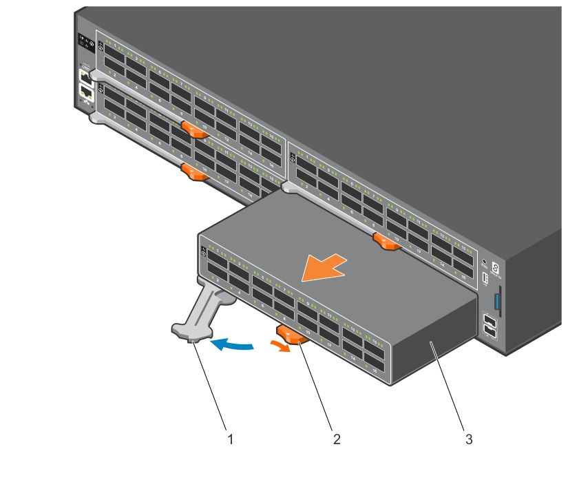
24 S6100–ON installationI/O module installation
NOTE: Install a blank panel in any unused switch I/O slot.
NOTE: The S6100-ON has capacitors on the front-left corner of the PC board. To avoid damaging these capacitors, align
the I/O module with the yellow arrows located inside the chassis and then gently slide the I/O module in place.
1. Remove the I/O module from the electro-static bag.
2. Open the left ejector lever, item 1, by pressing in the orange tab, item 2, and rotating it to the right.
The level snaps into the open position.
3. Slide the I/O module into the switch I/O slot.
The slot is keyed so that the I/O module fully inserts in only one way. When you install the I/O module correctly, it snaps into
place and is flush with the back of the switch.
Figure 20. I/O module installation
a. Ejector lever
b. Orange release tab
c. I/O module
Important points
The S6100–ON is designed to support two hot-swappable power supplies with integrated fans that provide cooling for the
chassis.
● The S6100–ON ships with two power supplies.
● The PSU slides into the slot smoothly. Do not force the PSU into a slot as this action may damage the PSU or the S6100-ON
chassis.
S6100–ON installation 25● The S6100–ON supports AC and DC power supplies with two air-flow directions—I/O to PSU and PSU to I/O. The S6100–
ON does not support mixing PSU types. The fan airflow direction for the PSUs must be the same.
● Module power is software controlled. You do not see module LEDs when the system powers up.
CAUTION: DO NOT mix airflow directions. Both power supplies must use the same airflow direction—I/O to PSU
or PSU to I/O.
NOTE: Although the switch can run on one PSU, Dell highly recommends using two PSUs for full redundancy and extra
cooling. To avoid overheating when the switch is running with a single PSU, install the second PSU.
NOTE: ESD damage can occur if components are mishandled. Always wear an ESD-preventive wrist or heel ground strap
when handling the S6100–ON and its components.
NOTE: To prevent electrical shock, ensure that the S6100–ON is grounded properly. If you ground your equipment
incorrectly, excessive emissions may result. To ensure that the power cables meet your local electrical requirements, use a
qualified electrician.
NOTE: The Utility panel consists of two slots, PSU1 and PSU2. Insert PSUs in both slots.
NOTE: If you remove and re-insert a module in the same slot, the system detects the module. However, if you remove a
module from a slot and insert a different module into that same slot, the system does not detect the new module.
SFP+ and QSFP optics installation
The S6100–ON has SFP+, QSFP+, and QSFP28 optical ports.
For a list of supported optics, contact your Dell representative.
CAUTION: ESD damage can occur if components are mishandled. Always wear an ESD-preventive wrist or heel
ground strap when handling the S6100–ON and its components.
WARNING: When working with optical fibers, follow all warning labels and always wear eye protection. Never
look directly into the end of a terminated or unterminated fiber or connector as this action can cause eye
damage.
1. Position the optic so it is in the correct position.
The optic has a key that prevents it from being inserted incorrectly.
2. Insert the optic into the port until it gently snaps into place.
NOTE: When you cable the ports, be sure not to interfere with the airflow from the small vent holes above and below
the ports.
SFP+ and QSFP optics removal
Remove an SFP+, QSFP+, or QSFP28 optic by pulling the tab on the optic and sliding the optic from the port.
CAUTION: When removing optics with direct attach cables (DACs) from the port, pull the release tab firmly and
steadily. If you have difficulties pulling out the cable, gently push the optic into the port with one hand and at
the same time pull the release tab slightly upwards, towards the cable or module center, with the other hand. Do
not jerk or tug repeatedly on the tab.
Port connectivity
Dell recommends you distribute port groups across all four port pipes.
The S6100-ON switch has four port pipes, also known as packet processing pipelines. Because S6100-ON is a modular switch,
connectivity between the front panel ports and the port pipes depends on the module type of the four slots. For the best buffer
resource usage, distribute the functional port groups, such as downlinks, uplinks, interchassis links, LAGs, and ECMP across all
four port pipes—0, 1, 2, and 3. If that is not possible, distribute the port groups across port pipes 0 and 2 or port pipes 1 and 3.
26 S6100–ON installationFor example, with 8 x 100G modules, create a two-port LAG using port 1/7 from port pipe 0 and port 1/4 from port pipe 2. With
16 x 40G modules, create a four-port LAG using port 1/12 from port pipe 1, 1/14 from port pipe 0, 2/11 from port pipe 2, and
2/13 from port pipe 3. With 4 x CXP + 4 x QSFP28 modules, create a two-port LAG using port 1/6 from port pipe 1 and port 2/7
from port pipe 2.
The following tables list the port to port pipe connectivity for the 8 x 100G modules, 16 x 40G modules, and 4 x CXP + 4 x
QSFP28 modules:
Table 6. Port and port pipe distribution—8 x 100G modules
Slot/Port Port pipe
1/7, 1/8, 2/1, 2/2, 3/1, 3/2, 4/3, 4/4 0—red
1/5, 1/6, 2/3, 2/4, 3/7, 3/8, 4/5, 4/6 1—orange
1/3, 1/4, 2/5, 2/6, 3/5, 3/6, 4/7, 4/8 2—green
1/1, 1/2, 2/7, 2/8, 3/3, 3/4, 4/1, 4/2 3—blue
Figure 21. 8 x 100G module port pipes
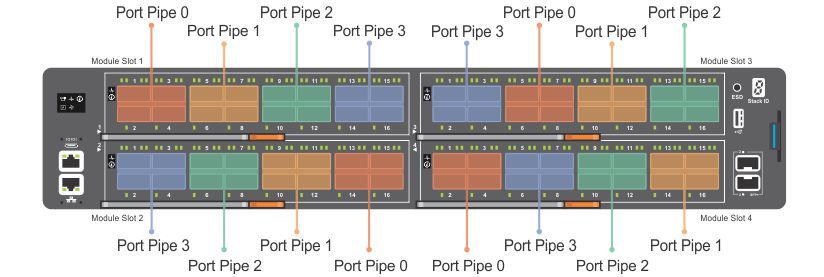
Table 7. Port and port pipe distribution—16 x 40G modules
Slot/Port Port pipe
1/13, 1/14, 1/15, 1/16, 2/1, 2/2. 2/3. 2/4, 3/1, 3/2, 3/3, 3/4, 0—red
4/5, 4/6, 4/7, 4/8
1/9, 1/10, 1/11, 1/12, 2/5, 2/6, 2/7, 2/8, 3/13, 3/14, 3/15, 1—orange
3/16, 4/9, 4/10, 4/11, 4/12
1/5, 1/6, 1/7, 1/8, 2/9, 2/10, 2/11, 2/12, 3/9, 3/10, 3/11, 3/12, 2—green
4/13, 4/14, 4/15, 4/16
1/1, 1/2, 1/3, 1/4, 2/13, 2/14, 2/15, 2/16, 3/5, 3/6, 3/7, 3/8, 3—blue
4/1, 4/2, 4/3, 4/4
Figure 22. 16 x 40G module port pipes
S6100–ON installation 27Table 8. Port and port pipe distribution—4 x CXP + 4 x QSFP28 modules
Slot/Port Port pipe
1/7, 1/8, 2/1, 2/2, 3/1, 3/2, 4/3, 4/4 0—red
1/5, 1/6, 2/3, 2/4, 3/7, 3/8, 4/5, 4/6 1—orange
1/3, 1/4, 2/5, 2/6, 3/5, 3/6, 4/7, 4/8 2—green
1/1, 1/2, 2/7, 2/8, 3/3, 3/4, 4/1, 4/2 3—blue
Figure 23. 4 x CXP + 4 x QSFP28 port pipes
System power-up
Supply power to the S6100–ON after it is mounted in a rack or cabinet.
Dell recommends reinspecting your system before powering up. Verify the following:
● The equipment is properly secured to the rack and properly grounded—recommended.
● The equipment rack is properly mounted and grounded—recommended.
● The ambient temperature around the unit, which may be higher than the room temperature, is within the limits specified for
the S6100–ON, see Specifications.
● There is sufficient airflow around the unit.
● The input circuits are correctly sized for the loads and that you use sufficient overcurrent protection devices.
● All protective covers are in place.
● All I/O modules are installed.
CAUTION: Do not power up the switch if you did not install a fan module.
NOTE: A US AC or DC power cable is included for powering up an AC or DC power supply. You must order all other power
cables separately.
NOTE: ESD damage can occur if components are mishandled. Always wear an ESD-preventive wrist or heel ground strap
when handling the S6100–ON system and its components.
Power up sequence
When the system powers up, the fans immediately come on at high speed. The fan speed slows as the system continues to boot
up.
1. Verify that the power source complies with the system input power requirements.
2. Connect a power plug to each power connector. Make sure that the power cord is secure.
3. Connect the power cable to each power supply and to a power source. The PSU LED for power blinks green to indicate that
each PSU is receiving power from an outlet.
When you turn on the power supplies and supply power to the chassis, the system performs a series of power-on self-tests
(POSTs). No user interaction is required during the POST.
NOTE: Module power is software controlled. You do not see module LEDs when the system powers up in ONIE.
28 S6100–ON installation6
Power supplies
The S6100–ON supports AC or DC power supplies with two air-flow directions, normal and reverse. Normal airflow is from the
I/O to the PSU and reverse airflow is from the PSU to the I/O.
Two PSUs are required for full redundancy, but the system can operate with a single PSU. To protect against high-voltage
shock, install a power supply blank in all unused power supply slots.
The PSU is field replaceable. When running with full redundancy—two power supplies installed and running, you can remove and
replace one PSU without disrupting traffic.
CAUTION: To prevent electrical shock, ensure that the S6100-ON is grounded properly. If you do not ground
your equipment correctly, excessive emissions may result. Use a qualified electrician to ensure that the power
cables meet your local electrical requirements.
NOTE: Connect the power supply to the appropriate branch circuit protection as defined by your local electrical codes.
Verify that the remote power source complies with the system input power specifications.
NOTE: ESD damage can occur if components are mishandled. Always wear an ESD-preventive wrist or heel ground strap
when handling the S6100–ON and its components.
Topics:
• Components
• AC or DC power supply installation
• AC or DC power supply replacement
Components
The following power supply options are available for the S6100–ON:
● AC or DC power supply with integrated fan
● AC or DC power supply with integrated reverse flow fan
Both PSUs are on the right side of the switch. Power supply 1, PSU1, is on the top of the chassis; power supply 2, PSU2, is on
the bottom of the chassis.
Figure 24. S6100–ON PSUs
1. PSU 1 and 2
The PSUs have an integrated fan, which you cannot replace individually; if the fan integrated in a PSU fails, you must replace
the entire PSU. You can replace the fan trays individually. For fan tray replacement procedures, see Fans.
WARNING: Prevent exposure and contact with hazardous voltages. Do not attempt to operate this system with
the safety cover removed.
Power supplies 29CAUTION: Remove the power cable from the PSU before removing the PSU. Also, do not connect the power
cable before you insert the PSU in the chassis.
NOTE: To comply with the GR-1089 Lightning Criteria for Equipment Interfacing with AC Power Ports, use an external
surge protection device (SPD) at the AC input of the router.
AC or DC power supply installation
NOTE: The PSU slides into the slot smoothly. Do not force a PSU into a slot as this action may damage the PSU or the
S6100–ON chassis.
NOTE: Ensure that you correctly install the PSU. When you install the PSU correctly, the power connector is on the right
side of the PSU.
1. Remove the PSU slot cover from the S6100-ON using a small #1 Phillips screwdriver.
2. Remove the PSU from the electro-static bag.
3. Use the grab handle and the orange tab to insert the PSU into the switch PSU slot.
Insert the PSU exposed PCB edge connector first. The PSU slot is keyed so that the PSU can only be fully inserted in one
orientation.
Figure 25. Power supply installation
a. Power supply unit
b. Release tab
When you install the PSU correctly, it snaps into place and is flushed with the back of the switch.
4. Plug in the appropriate AC three prongs power cord from the switch PSU to the external power source.
5. Repeat steps 1 through 4 above using the second PSU slot on the S6100-ON system.
NOTE: The S6100-ON powers up when the cables are connected between the power supply and the power source.
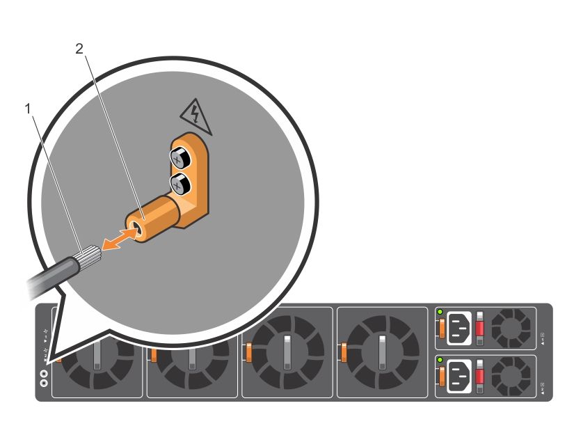
30 Power suppliesDC power supply connection
Each DC powered system comes with a set containing a prewired, 3-inch 8 AWG, power supply connector and a four-screw
wiring block. One set is provided for each DC PSU.
Figure 26. DC power connector and wiring block
1. DC wire RTN 2. DC power connector
3. Two Captive screws 4. Release tab
5. PSU status LED 6. DC power socket
7. DC wire –48V
Figure 27. DC power connector ground
1. Ground nut 2. Washer
3. Lock washer 4. Ground cable
5. Device grounding rod
1. Strip 1/2 inches of insulation from each of the power connector’s red and black wires, as shown.
2. Insert each of the power connector’s bare wire lengths into the wiring block. Insert red into one hole and black into the other
hole, as shown.
Power supplies 313. Use a flat-blade screwdriver to tighten the screws that secures the bare wires into the wiring block.
4. Secure the site’s DC power source wires to the other side of the wiring block, see steps 1 and 3.
NOTE: Do not cross the wires—in the wiring block, red aligns with red and black aligns with black.
5. Insert the DC power connector into the power socket of the DC PSU. Ensure that the connector pins firmly seat and you
hear the click of the power connector’s left and right levered clamps lock into place.
NOTE: Never try to force the power connector into or out of the DC PSU power socket.
NOTE: To remove the power connector from a DC PSU, squeeze the levers on both sides of the connector. Doing so
disengages the power connector’s clamps. While continuing to squeeze, pull the power connector from the DC PSU socket.
AC or DC power supply replacement
CAUTION: Disconnect the power cord before removing the power supplies. Also, disconnect all power cords
before servicing.
NOTE: The PSU slides into the slot smoothly. Do not force a PSU into a slot as this action may damage the PSU or the
S6100–ON chassis.
NOTE: If a PSU fails, you must replace the entire unit. There are no field serviceable components in the PSU. To request a
hardware replacement, see Dell Support.
1. Disconnect the power cable from the PSU.
2. Use the grab handle and the orange tab to slide the PSU out of the power supply bay.
3. Use the grab handle and the orange tab on the replacement PSU to slide it into the power supply bay.
4. Attach the power cord to the replacement PSU.
NOTE: The system powers up when the cables are connected between the power supply and the power source.
32 Power supplies7
Fans
The S6100–ON comes from the factory with two PSUs and four fan module installed in the chassis. The fan module and power
supply, which have integrated fans, are hot-swappable.
In addition to the power supply modules, you can order and install fan modules separately.
The S6100-ON supports two airflow direction options. DO NOT mix airflow types in a chassis; you can use only a single airflow
direction in a chassis. If the airflow directions are mismatched, the S6100-ON issues an alarm. You must correct the mismatched
airflow direction.
The fans and PSUs are color coded for air flow direction. Red is normal air flow and blue is reverse air flow.
● Normal—airflow is from the I/O panel to the PSU—red.
● Reversed—airflow is from the PSU to the I/O panel—blue.
All fans and PSUs in a configuration must be in the same airflow direction.
Environmental factors can decrease the amount of time required between fan replacements. Check the environmental factors
regularly. An increase in temperature and particulate matter in the air might affect performance; for example, new equipment
installation.
CAUTION: Check the fans at six-month intervals and replace them as necessary. Regularly monitor the speeds
of the fans to accurately determine replacement intervals.
Topics:
• Components
• Fan module installation
• Fan module replacement
• Fan air filter replacement
• After system installation
Components
The following are the S6100–ON fan components:
● S6100–ON Fan module
● S6100–ON Fan module—reverse flow
Figure 28. S6100–ON fan modules
1. Fan modules
Fans 33You can also read