Technical Service Guide - GE CleanSpeak Wi-Fi Connect Dryers August 2015
←
→
Page content transcription
If your browser does not render page correctly, please read the page content below
GE Appliances

Technical Service Guide
August 2015

GE CleanSpeak™ Wi-Fi Connect Dryers

   GTD81ESPJMC
   GTD81GSPJMC
   GTD81ESSJWS
   GTD81GSSJWS
   GTD86ESPJMC
   GTD86GSPJMC
   GTD86ESSJWS
   GTD86GSSJWS

          GE Appliances
          General Electric Company
          Louisville, Kentucky 40225   31-9243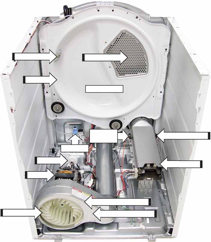
Safety Information

                           IMPORTANT SAFETY NOTICE
The information in this service guide is intended for use by individuals possessing
adequate backgrounds of electrical, electronic, and mechanical experience. Any
attempt to repair a major appliance may result in personal injury and property
damage. The manufacturer or seller cannot be responsible for the interpretation
of this information, nor can it assume any liability in connection with its use.

                                      WARNING
To avoid personal injury, disconnect power before servicing this product. If electrical
power is required for diagnosis or test purposes, disconnect the power immediately
after performing the necessary checks.

                    RECONNECT ALL GROUNDING DEVICES
If grounding wires, screws, straps, clips, nuts, or washers used to complete a path
to ground are removed for service, they must be returned to their original position
and properly fastened.

                                   GE Appliances
                               Technical Service Guide
                                  Copyright © 2015
   All rights reserved. This service guide may not be reproduced in whole or in part in
         any form without written permission from the General Electric Company.

                                         –2–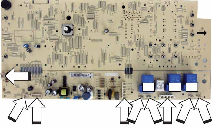
Table of Contents
Safety Information .......................................................................................................................................................................... 2

Nomenclature ................................................................................................................................................................................... 5

       Model Number .......................................................................................................................................................................... 5
Introduction........................................................................................................................................................................................ 6

Control Features ............................................................................................................................................................................. 7

Operating Instructions .................................................................................................................................................................. 8

Operating Instructions (continued) ......................................................................................................................................... 9

Dryer Features .................................................................................................................................................................................. 12

Communication................................................................................................................................................................................ 13

Reversing the Door Swing ........................................................................................................................................................... 14

Component Locator Views.......................................................................................................................................................... 16

       Electric Model ........................................................................................................................................................................... 16

       Gas Model .................................................................................................................................................................................. 17
Control Board Connector Locator View ................................................................................................................................ 18

Dryer Components.......................................................................................................................................................................... 19

         Control Panel........................................................................................................................................................................... 19

         Control Board Assembly ................................................................................................................................................... 20

         Top Panel .................................................................................................................................................................................. 21

         Front Panel ............................................................................................................................................................................... 21

         Door Switch ............................................................................................................................................................................. 22

         LED Drum Light ...................................................................................................................................................................... 22

         Front Bulkhead ...................................................................................................................................................................... 22

         Drive Belt and Drum ............................................................................................................................................................ 23

         Drum Rollers ............................................................................................................................................................................ 24

         Moisture Sensor .................................................................................................................................................................... 25

         Belt Switch................................................................................................................................................................................ 26

         Blower Wheel .......................................................................................................................................................................... 26

         Drum Motor ............................................................................................................................................................................. 27

         Long Vent Motor .................................................................................................................................................................... 28

         Heater Assembly ................................................................................................................................................................... 28

         Burner Assembly and Gas Conversion ....................................................................................................................... 29

         Gas Valve ................................................................................................................................................................................. 29

                                                                                                      –3–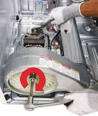
Gas Valve Coils ....................................................................................................................................................................... 30

          Ignitor ......................................................................................................................................................................................... 31

          Flame Detector ...................................................................................................................................................................... 31

          Ignitor Circuit Operation .................................................................................................................................................... 32

          Back Panel................................................................................................................................................................................ 33

          Rear Bulkhead ....................................................................................................................................................................... 33

          Inlet Safety Thermostat...................................................................................................................................................... 34

          Inlet Control Thermistor ..................................................................................................................................................... 35

          High Limit Thermostat ........................................................................................................................................................ 35

          Outlet Control Thermistor ................................................................................................................................................. 36

          Outlet Control Thermostat ................................................................................................................................................ 36
Steam Components........................................................................................................................................................................ 37

          Misting Nozzle......................................................................................................................................................................... 37

          Water Valve ............................................................................................................................................................................. 38
Troubleshooting ............................................................................................................................................................................... 39

Schematics and Wiring Diagrams ........................................................................................................................................... 50

Index ...................................................................................................................................................................................................... 56

Warranty ............................................................................................................................................................................................. 57

GE Dryer Warranty.......................................................................................................................................................................... 58

                                                                                                          –4–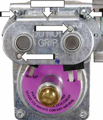
Nomenclature
Model Number

                           G T D 8 6 G S S J 0 W W

   Brand                                                                                   Color
   G - GE                                                                                  WW - White
   H - Café                                                                                BB - Black
   M - Moffatt                                                                             CC - Bisque
                                                                                           MV - Metallic Red
     Configuration                                                                         MG - Metallic Gold
     F - Front Load                                                                        MS - Metallic Black
     T - Top Load - Rear Control                                                           WS - Silver Backguard
     N - Top Load - Front Control                                                          WT - Titanium Backguard
     U - Unitized
                                                                           Engineering Digit
       Platform                                                            0-9
       W - Washer                                                                                     Model Year
       D - Std Vent                                                                                   F - 2015
       V - Long Vent                Series 1: 1 - 9                        Partner Type
       C - Condenser Dryer          Series 2: 1 - 9                        P - Premium (color)
       H - Heat Pump                1 - Compact                            H - Home Depot
       Z - Long Flat Back Dryer     4 - 24” Unitized                       L - Lowes
       X - Std Flat Back Dryer      7 - 27” Unitized                       S - Standard
                                                                           C - Contract (Hoses)
                                                        Product Type
                                                                           M - Mabe
                                  Fuel Type Dryer       R - Riser
                                  E - Electric          A - 2” Cover Top Load
                                  G - Gas               B - 4” Cover Top Load
                                  P - Propane           S - Stationary
                                                        P - Portable

The nomenclature breaks down and explains what the letters and numbers mean in the model number.

Serial Number
7KH¿UVWWZRFKDUDFWHUVRIWKHVHULDOQXPEHULGHQWLI\WKHPRQWKDQG\HDURIPDQXIDFWXUHThe letter
designating the year repeats every 12 years.
Example: LA123456S = June, 2013
                                                                              Technical Sheet    Note: The
                                                                                                 technical
A – JAN        2024 – Z                                                                          sheet is
D – FEB        2023 – V                                                                          located
F – MAR        2022 – T                                                                          inside the
G – APR        2021 – S                                                                          control
                                                                                                 panel.
H – MAY        2020 – R
L – JUN        2019 – M
M – JUL        2018 – L      The nomenclature
R – AUG        2017 – H      tag is located on             Nomenclature    Model Number

                                                                           Serial Number

S – SEP        2016 – G      the front panel
                             inside the door.
T – OCT        2015 – F
V – NOV        2014 – D
Z – DEC        2013 – A

                                                       –5–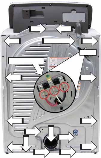
Introduction
GE CleanSpeak™ Dryer Features
GE CleanSpeak™ model dryers incorporate two steam features. These dryers do not utilize a separate steam
JHQHUDWRU,QVWHDGWKHGU\HUVXVHDZDWHUYDOYHDQGDVWHDPQR]]OHWKDWIXQFWLRQVDVD´PLVWLQJµRUL¿FH
which works in conjunction with the heat generated by the dryer to de-wrinkle clothing.
• Steam Refresh: Rejuvenate lightly worn clothes by getting rid of wrinkles and odors with this convenient
setting using the power of steam.
• Steam Dewrinkle: Stored or wrinkled clothes come out ready to wear with this helpful setting that uses
steam to refresh and dry a load of any size.
• CleanSpeak™ Communication System: Perfect drying performance is achievable thanks to the ability of
the washer to communicate with the dryer to preset the dry cycle.
• Wi-Fi Connect: Check dryer progress from your smartphone with an app that lets you monitor cycles,
settings, extended tumble time and receive alerts when clothes haven't been removed.
• Connected Home Ready
• 14 Dryer Cycles
2ȺHUHQKDQFHGGU\LQJSHUIRUPDQFHDQGIDEULFFDUH
• (QHUJ\6WDU4XDOL¿HG
0HHWVRUH[FHHGVIHGHUDOJXLGHOLQHVIRUHQHUJ\HȻFLHQF\IRU\HDUURXQGHQHUJ\
and money savings.
• HE SensorDry™: Allows the control to monitor the fabric for moisture content and end the cycle at the
desired moisture level.
• My Settings: Selection saves a favorite cycle for future use.
• Cycle Countdown Display with LED Indicators: Know exactly how much time is left for each cycle with
bright display and lights.
• Large 7.8 cubic foot dryer drum capacities.
• Integrated drying rack for drying delicate items, such as
washable sweaters.
• Dual Thermistors: Thermistors are more sensitive to
temperature changes and can relay the information faster
than thermostats. The dryer utilizes dual thermistors to
monitor incoming air temperature, as well as air temperature
leaving the drum. The sensors work together with the heat
and the blower to provide consistent, even heat.
• LED Drum Lamp
• Reversible Door
• Long Vent Models: Separate blower motor for long vent
applications.
• Built-in Service Test Mode
6SHFL¿FGU\HUFRPSRQHQWVFDQ
be operated. Fault codes are recorded and accessible on the
control panel display.
–6–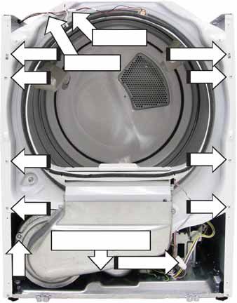
Control Features
Throughout this manual, features and appearance may vary from your model.
B D C G
Drum
Sanitized
Normal
Mixed Loads
Cottons Jeans
Towels / Sheets Casuals
Permanent Press 90 ~ 99 Extra Dry High
70 ~ 80 More Dry Medium
Bulky Items Active Wear ESTIMATED TOTAL CYCLE TIME
DRYING CLEAN 50 ~ 60 Dry Low
LINT FILTER
DAMP
Quick Dry Delicates COOL 30 ~ 40 Less Dry Extra Low
DOWN
DELAY
Energy Smart DRY 10 ~ 20 Damp No Heat
Quick Fluff Steam Refresh
No Heat
Time Level Temp
Timed Dry Steam Dewrinkle
Delay Extended Damp Rack Use Timed Dry
Dry Tumble Alert Dry Cycles Only
STEAMselect Hold 3 seconds
to CANCEL
Select Steam Cycle and PUSH “STEAMselect” for garment amount Good Best
1 to 2 3 to 5 6 to 7 8 to13
Dry
emonitor
A E F H
A Power
Press to “wake up” the display. If the display is active, press to put the dryer into idle mode.
NOTE: Pressing Power does not disconnect the appliance from the power supply.
B Start and Pause
Press Start to begin the cycle. NOTE: The door must be closed for the dryer to start the cycle.
Pressing Pause will pause the cycle, the Start will blink and “PAUSE” will scroll across the LCD.
To continue the cycle, press Start again. To stop the cycle, hold the button for 3 seconds.
C Display and Status Lights
The display shows the approximate time remaining until the end of the cycle.
In addition, this display will, “scroll” the dryer status:
• PAUSE The message “PAUSE” will scroll across the display when the dryer’s cycle
is paused. The cycle may be re-started by pressing the Start button.
• door The message “door” will be displayed when the door is opened during the
dryer’s cycle.
• CyCLE The message “CyCLE” will be displayed when the clothes are dry and
the dryer is recommending a preferred cycle for the next load (see
CleanSpeak™ in the Communication section of this Guide).
• dELAY The message “dELAY” will be displayed when the Delayed Dry is initiated.
It will be replaced with the estimated time when the cycle starts.
Cycle Status Lights
Shows whether the dryer is in the DRYING, DAMP, or COOL DOWN cycle.
Feature status lights indicate:
The My Settings feature is on for this cycle.
The dryer is locked - will blink once if any button is pressed or the cycle knob is
turned.
The signal is on. See the Variable Signal description under the My Settings
later in this section..
The Clean Lint Filter light will stay on for 15 seconds after the cycle stops.
The eDry feature is selected.
A Delay Dry time is set.
(Continued next page)
–7–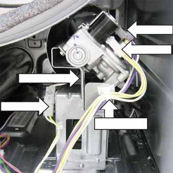
Operating Instructions
D   Drying Cycles - Sensor cycles automatically determine fabric dryness.
    Timed cycles run for the selected time.
          Timed Dry              Set the Cycle Selector at the desired drying time.
          $LU)OXȹ1R+HDW       )RUIUHVKHQLQJRUÀXȻQJXSDOUHDG\GU\FORWKLQJIDEULFOLQHQV
                                 and pillows. Use with No Heat.

                                 Provides 10 minutes of no-heat tumbling.
          Speed Dry              For small loads that are needed in a hurry, such as sport or
                                 school uniforms. Can also be used if the previous cycle left some
                                 items damp, such as collars or waistbands. NOTE: On some
                                 models, the time remaining in the cycle will show counting down
                                 in the display.
          Bulky Items            For large coats, bed spreads, mattress covers, sleeping bags and
                                 similar large/bulky items such as blankets, comforters, jackets,
                                 and small rugs.
          7RZHOV6KHHWV          For most towels and linens.
          &RWWRQV                For cottons and most linens. NOTE: Energy Star® models are
                                 tested on cottons with default settings.
          0L[HG/RDGV            For loads consisting of cottons and poly-blends.
          -HDQV                  For jeans.
          &DVXDOV(DV\&DUH       For wrinkle-free, permanent press, delicate items and knits.
          Active Wear            For sports and exercise wear.
          Delicates              For delicate items, special-care fabrics and knits.
          Steam Refresh          )RUVOLJKWO\ZULQNOHGGU\JDUPHQWV6LJQL¿FDQWO\UHGXFHVZULQNOHV
                                 NOTE: A single extremely light fabric item may need to have an
                                 additional item included in the Steam Refresh cycle to achieve
                                 optimum results.
          Steam Dewrinkle        For use with larger loads than Steam Refresh. Ideal for loads left
                                 in the dryer for an extended time.
          Steam Select           The Steam Select button is used in conjunction with Steam
                                 Refresh and Steam Dewrinkle$VWKHEXWWRQLVSUHVVHGLWGH¿QHV
                                 how many articles are in the dryer and adjusts the steam and
                                 cool down times accordingly.

      *Cycles available with Sanitize option.

                                                                                (Continued Next Page)
                                            –8–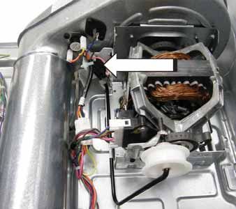
Operating Instructions (continued)
D   Drying Cycles - Sensor cycles automatically determine fabric dryness.
    Timed cycles run for the selected time.
    Steam Cycle Notes:
          • Important: The temperature setting must be set to HIGH and water must be turned
              on before running the steam cycles.
          • The Extended Tumble option will be turned on.
          •     After the steam cycle, the unit will beep (if Volume is on) and display “00”.
          •     Do not use a steam cycle with items such as wool, leather, silk, lingerie, foam
                products or electric blankets.
          • 'RQRWXVHVWHDPF\FOHVRQQHZFORWKHVZLWKRXW¿UVWZDVKLQJ
          • Steam cycles are not intended for use with towels.
                       Sanitized       This option reduces certain types of bacteria by 99.9%, including:
                                       Staphylococcus aureus, Pseudomonas aeruginosa and Klebsiella
                NSF Protocol P154
           Sanitization Performance of
                                       pneumoniae. The anti-bacterial process occurs when high heat is
            Residential Clothes Dryers
                                       used during a portion of the drying cycle.

                                 NOTE: Do not use this cycle on delicate fabrics.
    *Cycles available with Sanitize option.
      7KH6DQLWL]HG&\FOHLV&HUWL¿HGE\16),QWHUQDWLRQDO IRUPHUO\1DWLRQDO6DQLWDWLRQ
    Foundation) to NSF Protocol P154 Sanitization Performance of Residential Clothes Dryers.

E   Settings

    Individual settings for Timed Dry cycle minutes (Time), dryness level (Level), and temperature
    (Temp) can be set from the minimum (lowest in column) to maximum (highest in column). In
    general, the higher up the column, the more energy will be used.
    Time - Selection only for Timed cycles.
                               Each “setting” allows you to specify a lower (1 tap) or an upper
                               (2 taps) time working your way from a minimum 10 minute to a
                               maximum 99 minute dry time (10, 20, 30, 40, . . . 80, 90, 99, 10 . . .)
    Dryness Level - Selection only used for Sensor cycles. Timed cycles run for the selected time.

          Extra Dry              Use for heavy-duty fabrics or items that should be very dry, such
                                 as towels.
          More Dry               Use for heavy-duty or mixed type fabrics.
          Dry                    Use for a normal dryness level suitable for most loads. This is the
                                 preferred cycle for energy savings.
          Less Dry               Use for lighter fabrics.
          Damp                   For leaving items partially damp.

                                                                                    (Continued Next Page)
                                              –9–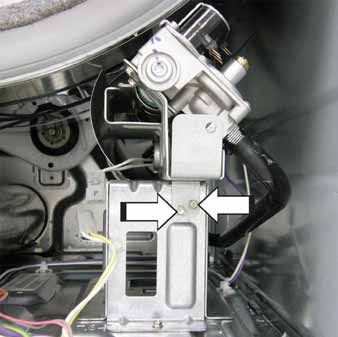
E   Temperature
          High                  For regular to heavy cottons.
                                NOTE: Steam Dewrinkle and Steam Refresh require the High
                                temperature setting.
          Medium                For synthetics, blends, delicates and items labeled permanent
                                press.
          Low                   For delicates, synthetics and items labeled tumble dry low.
          Extra Low             For delicates, synthetics and items labeled tumble dry low.
          No Heat               )RUÀXȻQJLWHPVZLWKRXWKHDW)RUXVHRQO\ZLWKWKH7LPHG'U\
                                cycles.

F   Options
    Delay Dry
    As the Delay Dry button is repeatedly pressed, the delay time sets from 1 to 9 hours, and
    back to clear (0). After selecting the delay time, press Start and the delay time will count down
    the time remaining until the cycle starts.
    If the Delay Dry button is pressed for 3 seconds, it clears (regardless of the delay time) or
    terminates a delaying cycle.
    Extended Tumble
    Use this option to minimize the wrinkles in clothes. It provides 1 hour of no-heat tumbling
    after the clothes are dry. If you are using the cycle Volume and you select the Extended
    Tumble option, a signal will sound at the end of the drying time and every 5 minutes during
    the Extended Tumble cycle. This will remind you that it is time to remove the clothes.
    Damp Alert
    This option causes the dryer to beep when clothes have dried to a damp level. Remove items
    that you wish to hang dry. The Damp Alert will only beep when this option is selected (but the
    dry cycle will keep running). Removing clothes and hanging them when they are damp can
    reduce the need to iron some items. The light beside the button will be lit when Damp Alert is
    on.
    Rack Dry
    Rack Dry is only allowed for timed cycles (Timed Dry & $LU)OXȹ 7KHOLJKWWXUQVRȺLIF\FOH
    knob is turned to a non-timed cycle.

                                            – 10 –
G My Settings
As the cycle selector knob is turned, the Time (Timed Dry), Level (Dryness Level), and Temp
(Temperature VHWWLQJVFKDQJHWRDXWRPDWLFSUHVHWGHIDXOWVHWWLQJV,I\RXGHVLUHDGLȺHUHQW
setting, press the appropriate button(s). Then press and hold the My Settings button for 3
seconds. The status heart and button lights will turn on, and the dryer will save these settings
for that knob selection. In the future, when you turn the selector knob to that cycle, your
settings will be automatically recalled.
To temporarily (for this load) return to the pre-set default settings, depress the My Settings
EXWWRQIRUDVHFRQG7KHVWDWXVKHDUWDQGEXWWRQOLJKWVZLOOWXUQRȺDQGWKHRSWLRQVZLOO
change back to these defaults. To make these default settings permanent, hold the My
Settings button again for 3 seconds to make them your preferred settings (the lights will turn
back on).
NOTE: Variable Signal volume cannot be set for My Settings.
Variable Signal
Use the Variable Signal button to change the volume of the end of cycle and control signals.
3UHVVWKHEXWWRQXQWLO\RXUHDFKWKHGHVLUHGYROXPH ORZPHGKLJK RURȺ7KHFORWKHVVKRXOG
EHUHPRYHGZKHQWKHEHHSHUJRHVRȺVRZULQNOHVGRQRWVHWLQ
NOTE:
• Remove garments promptly at the sound of signal. Place clothes on hangers so wrinkles
will not set in.
• Use the Variable Signal especially when drying fabrics like polyester, knits and permanent
press. These fabrics should be removed so wrinkles will not set in.
Drum Light
The drum light will go on if the Drum Light button is pushed or the door is opened. It will stay
on until the door is shut or the Drum Light or Power button is pushed.
Control Lock
You can lock the controls to prevent any selections from being made. Or you can lock the
controls after you have started a cycle. Children cannot accidentally start the dryer by
touching buttons with this option selected.
To lock the dryer controls, press and hold the Control Lock button for 3 seconds. The control
lock icon will light up when locked.
To unlock the dryer controls, press and hold the Control Lock button for 3 seconds.
NOTE: The Power button can still be used when the machine is locked.
H eDry
Available for Bulky Items, 7RZHOV6KHHWV, Cottons, 1RUPDO0L[HG/RDGV, Jeans, &DVXDOV
Permanent Press, Active Wear, and Delicates. When the eDry button is pressed, cycle
settings change to reduce the total energy consumption of the selected sensor cycle.
NOTE: Cycle times will change when eDry is selected.
The eMonitor lights display the relative energy use of your selected cycle and options. They
are provided as an energy guide and range from Good (1 light) to Better (5 lights). Cycle (time),
dryness level, temperature, and additional tumble options can increase or decrease your
HQHUJ\HȻFLHQF\6RPHVSHFLDOF\FOHVZLOOQRWSURYLGHDGLVSOD\
– 11 –Dryer Features
Sensor Dry This feature is activated in all but This dryer will adjust the initial
the Timed (Timed Dry & Quick estimated drying time of the
)OXȺ) and Steam (Steam Refresh & sensor dry cycles as it “learns”
Steam Dewrinkle) cycles. LWVLQVWDOODWLRQDQGXVDJHSUR¿OH
Please allow several weeks for
The Sensor Dry provides greater the dryer to customize itself to
drying accuracy than standard “you”.
machines, resulting in shorter dry
times and better clothes care. As
the clothes tumble, they touch a
moisture sensor. The sensor will
stop the heating cycle as soon
as the clothes have reached the
selected dryness.
Time Dry This feature is activated in Timed
'U\ 4XLFN)OXȺ cycles. The time
(10, 20, 30, 40, . . . 80, 90, 99) is
VSHFL¿HGYLDWKHTime button.
Steam Cycle This feature is activated in Steam
Refresh & Steam Dewrinkle cycles.
Use STEAMselect to indicate the
number articles.
Drying Rack (on some models) To use the drying rack:
Two back legs on the
rear wall angled ledge A handy drying rack may be used 1. Insert the drying rack into
for drying items such as tennis the dryer opening with
shoes. Hook the rack over the lint the two leg side toward
¿OWHUVRWKHUDFNH[WHQGVLQWRWKH the back and four leg side
dryer drum. toward the front.
NOTE: 2. Place the two back legs on
the rear wall angled ledge.
• The drying rack must be used
with the Timed Cycle. 3. Secure front two inner
straight legs into the oval
• Do not use this drying rack holes on both sides of the
when there are other clothes in OLQW¿OWHUKDQGOH
Secure front two inner straight the dryer.
legs into the oval holes on both
sides of the lint filter handle NOTE: Rotate the dryer drum by
hand clockwise to make sure
WKHEDȼHVFOHDUWKHUDFN
Stainless Steel Drum The stainless steel used to make drum will not rust or corrode.
the dryer drum provides the highest These surface blemishes will not
reliability available in a GE dryer. If DȺHFWWKHIXQFWLRQRUGXUDELOLW\
the dryer drum should be scratched of the drum.
or dented during normal use, the
Drum Light The drum light is an LED light.
Replacement must be done by a
TXDOL¿HGWHFKQLFLDQ
– 12 –Communication
CleanSpeakTM This dryer can communicate with a At the end of the wash cycle, the washer sends a
compatible washer (one whose Owner’s Manual signal to the dryer to indicate a preferred dry cycle.
contains a CleanSpeak™ description) via a standard When the dryer becomes idle (“End” display times
Cat-5e Ethernet cable with RJ45 male connectors out - or- the door is opened) “CYCLE” will scroll
(not included). This cable may be purchased across its cycle time display, its current cycle knob
separately. VHWWLQJ/('ZLOOEHOLWDQG LIGLȺHUHQW DVHFRQG
Connection points recommended cycle LED will blink. If “CYCLE” times
will vary by model out, pressing Power will refresh it and the LEDs. If
the dryer cycle knob is turned , the solid LED will
move accordingly. Pressing the dryer Start will
Washer LQLWLDWHWKHF\FOHNQREVHWWLQJ VROLG/(' DQGWXUQRȺ
Dryer WKHUHFRPPHQGHG EOLQNLQJ/(' LIDGLȺHUHQWF\FOHLV
Order on-line at GEApplianceParts.com today, 24 started.
hours a day or by phone at 800.626.2002 during
normal business hours. NOTE: CleanSpeak™ CYCLE times out after 5
Part Number Accessory minutes. Pressing the power button will refresh
DR07X10005 6’ cable - CleanSpeak™ CYCLE and the LEDs no matter how long it has been
communication timed out.
PBX10W00Y0 Wi-Fi ConnectPlus module
Wi-Fi Connect Some CleanSpeak™ dryers will Please visit www.GEAppliances.com/connect to
be Wi-Fi connect enabled through the use of a learn more about connected appliance features, to
built in communication card. Some will require learn what connected appliance app’s will work with
a Wi-Fi ConnectPlus module (PBX10W00Y0) to a smartphone
be compatible. This will allow the appliance to
communicate with a smartphone for remote Wi-Fi Connectivity: For assistance with the
DSSOLDQFHPRQLWRULQJFRQWURODQGQRWL¿FDWLRQV8VH appliance or the ConnectPlus network connectivity,
of the Cat-5e cable is not needed when connected please call 800-GE-CARES.
to Wi-Fi. If the cable is connected, the Wi-Fi will not
operate.
This device complies with Part 15 of the FCC Rules. Operation is subject to the following two conditions:
1. This device may not cause harmful interference, and
2. This device must accept any interference received, including interference that may cause undesired
operation.
This equipment has been tested and found to comply with the limits for a Class B digital device, pursuant
to Part 15 of the FCC Rules. These limits are designed to provide reasonable protection against harmful
interference in a residential installation. This equipment generates uses and can radiate radio frequency energy
and, if not installed and used in accordance with the instructions, may cause harmful interference to radio
communications. However, there is no guarantee that interference will not occur in a particular installation. If
this equipment does cause harmful interference to radio or television reception, which can be determined by
WXUQLQJWKHHTXLSPHQWRȺDQGRQWKHXVHULVHQFRXUDJHGWRWU\WRFRUUHFWWKHLQWHUIHUHQFHE\RQHRUPRUHRI
the following measures:
• Reorient or relocate the receiving antenna.
• Increase the separation between the equipment and receiver.
• &RQQHFWWKHHTXLSPHQWLQWRDQRXWOHWRQDFLUFXLWGLȺHUHQWIURPWKDWWRZKLFKWKHUHFHLYHULVFRQQHFWHG
• Consult the dealer or an experienced radio/television technician for help.
Labelling
&KDQJHVRUPRGL¿FDWLRQVWRWKLVXQLWQRWH[SUHVVO\DSSURYHGE\WKHPDQXIDFWXUHUFRXOGYRLGWKH
user’s authority to operate the equipment.
– 13 –Reversing the Door Swing
NOTE: These instructions are for changing the dryer 3. Loosen the bottom two right side hinge screws.
so that the door opens from the right side. Remove the door and place it on a protected,
ÀDWVXUIDFHWRDYRLGDQ\GDPDJH5HPRYHERWK
Tools Needed: the Blind Plate and the Strike Plate and install
• Standard #2 Phillips screwdriver them in opposite positions.
• Tape-tipped putty knife
• 6PDOOÀDWEODGHVFUHZGULYHU
Blind plate
Before Starting
Unplug the dryer from its electrical outlet.
Inner door
1. Open the door approximately 170 degrees. With Strike plate
a putty knife, remove the four plastic covers
located along the left side of the front panel and 4. Remove the four door hinge screws, the four
set them aside. edge screws, and the eight inside screws.
Plastic Cover (4) /LIWWKHLQQHUGRRUXSZDUGVXVLQJDÀDWEODGH
screwdriver.
Inside screws
Edge
screws
Inner door
Left side of
front panel
Inside screws
Door hinge
screws
2. Remove the bottom screw from each hinge
Outer door
(right side) and partially insert them into the top
left side hinge holes.
NOTE: All four front panel hinge screws will now be
in the top hinge holes; two on the left and two on
the right. NOTE: Some doors may have four inside screws and
four additional edge screws.
(Continued next page)
– 14 –5. Remove and swap the two cover caps and door 6. With the cover caps and door handle in place,
handle from the outer door: mount the inner door back into the outer door
A. Squeeze the tabs on the inside of the door with the screws that were removed in step 4.
handle clips. Push the clips through the Make sure to mount the hinges on the side
outer door. opposite of the handle.
B. Squeeze the tabs on the inside of the Inside screws
cover caps. Push the caps through the outer Door
door. hinge
screws
Inside of door
Edge Inside screws
screws
Handle
Door handle 7. Mount the assembled door on the two upper
Door handle clip
Cover cap left side hinge screws installed in step 2. Move
the hinge screws loosened in step 3 into the
lower left side screw holes. Tighten those screws
enough to hold the door but still allow a slight
C. Push the door handle clips into the openings adjustment. Close the door. Adjust the door so
on the opposite side of the outer door, there is equal gap on all sides. Carefully open
PDNLQJVXUHWRÀLSWKHKDQGOHVRLWFXUYHV WKHGRRUDQG¿UPO\WLJKWHQDOOIRXUVFUHZV
to the inside.
D. Push the cover caps into the openings on
the outer door where the handle used to be
installed.
Hang door and
Door tighten screws
Inside of door
Cover cap
8. Install the four plastic caps removed in step 1
Door handle clip
into the four right side front panel holes.
Door handle
NOTE: To return the door to the original setup, follow
these instructions, swapping “left” and “right”.
When Finished
Plug the dryer back into an electrical outlet.
– 15 –Component Locator Views
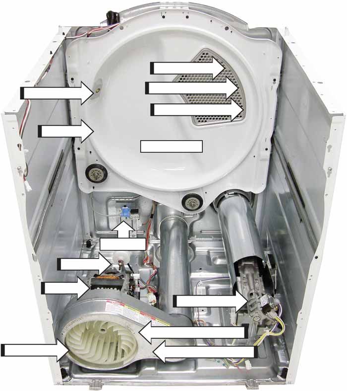
Electric Model
Misting Nozzle Inlet Thermistor**
Drum Back
Rear Bulkhead
Inlet Safety High Limit Thermostat
Thermostat
Water Valve
Idler Pulley
Heater Assembly
Motor
Outlet Control Thermostat*
Blower Wheel Outlet Control Thermistor*
* Located on back of blower housing
** Located behind rear bulkhead
(Continued Next Page)
– 16 –Gas Model
Inlet Thermistor**
Inlet Safety Thermostat**
Misting Nozzle
High Limit Thermostat**
Drum Back
Rear Bulkhead
Water Valve
Idler Pulley
Motor
Burner Assembly
Outlet Control Thermostat*
Blower Wheel Outlet Control Thermistor*
* Located on back of blower housing
** Located behind rear bulkhead
– 17 –Control Board Connector Locator View
J25
K4 K1 K3
J11
J8 J7 J6 J5 J4 J2
J10
J2 - Outer Coil (Electric), Gas Valve J25 - Sensor Rods, Earth Ground
J4 - Outer Coil (Electric) K1 - Outer Coil Relay (Electric), Gas Valve Relay
J5 - Drum Motor, L1, Steam, Long Vent Motor K2 - Drum Motor Relay
J6 - Inner Coil (Electric) K3 - Inner Coil (Electric) Relay
J7 - Inner Coil (Electric) SW1 - UI Control
J8 - L1, Neutral, Door Switch, Motor Centrifugal Switch
J10 - Outlet Control Thermistor, Inlet Control Thermistor,
ACM Module, Ground, GEA, 12 VDC
J11 - Drum Light
– 18 –Dryer Components
WARNING: Sharp edges may be exposed when 4. Disconnect the RJ45 connector and carefully lay
servicing the dryer. Use caution to avoid injury. Wear the control panel on its face to disconnect the
Kevlar® gloves or equivalent protection. harness connectors from the control board.
Control Panel 5. Remove the control panel rear cover by
removing the two retaining screws, then push
Removal of the control panel provides access to the back to disengage it from the two shoulder
control board assembly. The control panel is held bolts.
in place with three screws located at the top rear
of the control panel, and also with three shoulder
bolts located on the inside front of the control panel
bottom front.
Control Panel Removal
1. Disconnect the electrical power supply to the
GU\HUDQGWXUQRȺWKHJDVVXSSO\
2. Remove the three 1/4 in. hex head screws from
the top rear backsplash.
3. Grasp the front control panel bottom. Push
down slightly and back at the same time
allowing the control panel to roll forward.
– 19 –Control Board Assembly 3. Remove the eight Phillips head screws and the
control board frame from the control panel.
The control board assembly is mounted in a plastic
housing that is attached to the inside of the control
panel. It consists of two circuit boards connected by
a wire spine. The boards and the plastic housing are
replaced as an assembly.
Operation of the control board assembly can be
checked by using the service test mode. (See the
Service Test Mode section in this guide.)
)DXOWFRGHVWKDWDUHVSHFL¿FWRWKHFRQWUROERDUG
can initiate fault codes F05 and E06. (See the
Service Test Mode section in this guide.)
Control Board Assembly Removal
1. Disconnect the ACM (Appliance Communication
Module) wire harness from the control panel
rear cover.
2. Disconnect the wire harnesses from the control
panel.
– 20 –Top Panel Front Panel
Removal of the top panel provides access to the Removal of the front panel provides access to the
drum light. drum and drive belt. The front panel is held in place
by six screws and two bottom tabs on the frame.
Top Panel Removal
Front Panel Removal
1. Remove the control panel from the top panel
(see Control Panel Removal in this guide). 1. Remove the control panel (see Control Panel
Removal in this guide).
2. Remove the two Phillips head screws (one from
underneath each front corner) that attach the 2. Remove the top panel (see Top Panel Removal
top panel to the dryer. in this guide).
3. Press up on the two metal clips (one 3. Disconnect the door switch wires.
from underneath each front corner) and
simultaneously push the top panel forward 4. Remove the top two Phillips head screws (one
approximately 2 inches. from each top corner) that attach the front
panel to the dryer cabinet.
Metal Clip
Screw
Disconnect
Disconnect
4. Lift the top panel from the dryer.
5. Remove the four Phillips head screws that
attach the front panel to the front frame.
(Continued next page)
– 21 –6. Close the door. Grasp the top of the front panel Front Bulkhead
RQERWKVLGHVWLOWLWRXWWKHQOLIWWKHSDQHORȺWKH
two bottom tabs. 7KHIURQWEXONKHDGKRXVHVWKHOLQW¿OWHUKRXVLQJWZR
sensor rods, two front rollers, and drum light. It is
Door Switch located behind the front panel.
The door switch is fastened to the front panel by two Front Bulkhead Removal
locking tabs (one on each side). When the dryer door
1. Remove the control, top, and front panels. (See
is closed, the switch will complete the drum motor
Control Panel Removal, Top Panel Removal,
circuit, allowing dryer operation. When the door is
and Front Panel Removal in this guide.)
open, the switch will open the drum motor circuit,
interrupting dryer operation. Opening the dryer door 2. Remove the wire tie from the front bulkhead.
will also cause the drum light to be energized.
3. Disconnect the drum light wire harness.
7KHGRRUVZLWFKFDQEHUHPRYHGE\LQVHUWLQJDÀDW
EODGHVFUHZGULYHUEHKLQGWKHVZLWFKÀDQJHDQG 4. Disconnect the sensor rods wire harness.
carefully prying the switch out from the front panel.
Two wires are connected to the switch. 5. Loosen, but do not remove the top two Phillips
head screws that attach the front bulkhead to
The door switch circuit can be checked in the the side panels.
service mode.
6. Remove the remaining six Phillips head screws
that attach the front bulkhead to the side
panels.
7. Remove the two Phillips head screws that attach
the bottom of the front bulkhead to the blower
housing.
8. /LIWWKHIURQWEXONKHDGRȺWKHWRSWZRVFUHZV
Disconnect
Loosen Loosen
LED Drum Light Wire Tie
The LED drum light is attached to the front bulkhead
with two clips. To access the drum light, it will be
necessary to remove the top panel. It is necessary to
disconnect the drum light wire harness and squeeze
both clips to remove the LED drum light.
The LED drum light receives approximately 3.8 VDC
from the control board J11 connector.
Screw (below duct)
Disconnect
Disconnect
Clip Clip
– 22 –Drive Belt and Drum Drive Belt Installation
The drum rotates clockwise, as viewed from the 1. Place the belt in position around the
front, at a speed of 46 - 50 rpm. The drive belt circumference of the drum.
extends from the motor pulley, past the idler pulley,
and around the perimeter of the dryer drum. 2. Reach under the left side of the drum and place
the belt in position around the motor and idler
Drive Belt Removal pulleys.
1. Remove the control, top, and front panels. (See 3. Release the idler pulley and guide the belt into
Control Panel Removal, Top Panel Removal, position.
and Front Panel Removal in this guide.)
NOTE: The belt should be oriented so that the belt
2. Remove the front bulkhead. (See Front Bulkhead grooves contact the motor pulley.
Removal in this guide.)
Non-Long Vent Model
3. To release belt tension, reach under the left side
of the drum, push the idler pulley to the left, then
lock the idler arm into the top indentation on the
idler arm bracket. (See photo, drum removed for
clarity.)
Non-Long Vent Model
Idler Pulley
Long Vent Model
Idler Arm Idler Arm Bracket
Long Vent Model
Idler Arm
Idler Arm Bracket
Idler Pulley
4. Remove the belt from the motor pulley and idler
pulley.
5. Guide the belt out from the dryer cabinet.
(Continued Next Page)
– 23 –NOTE: Before installing the front panel, slowly rotate Drum Rollers
the drum in both directions to ensure that the belt is
aligned and not twisted. The stainless steel drum rotates on four drum rollers
(two on the front drum support and two on the rear
Drum Removal drum support).
1. Remove the belt from the motor pulley and idler Each drum roller comes as a complete assembly.
pulley. (See Drive Belt Removal in this guide,
and follow steps 1 through 3.)
2. Using the belt as a handle, pull the drum
forward and guide it out of the dryer cabinet.
Drum Roller Removal
1. Remove the front bulkhead to access the front
drum rollers. Remove the drum (See Drum
Removal in this guide), to access the rear drum
rollers.
2. Each drum roller is held in place by a plastic
triangular clip. Remove the triangular clip with a
CAUTION: To prevent damage to the dryer, the drum VPDOOÀDWEODGHGVFUHZGULYHUDQGVOLGHWKHGUXP
must be installed with the blue threaded felt seal UROOHURȺWKHUROOHUVKDIW
toward the back of the dryer.
To remove the left side drum roller shaft from the
front bulkhead:
1. Remove the front bulkhead. (See Front Bulkhead
Removal in this guide.)
2. Remove the 9/16 in. hex nut that attaches the
shaft to the front bulkhead.
Blue Thread
To remove the right side drum roller shaft from
the front bulkhead:
1. Remove the front bulkhead. (See Front Bulkhead
Removal in this guide.)
2. 5HPRYHWKHOLQW¿OWHU
3. Disconnect the sensor wires.
NOTE
7KHVHQVRUURGVDUHSDUWRIWKHOLQW¿OWHU
KRXVLQJ7RUHSODFHWKHVHQVRUURGVWKHOLQW¿OWHU
housing must be replaced.
(Continued Next Page)
– 24 –4. Remove the two Phillips head screws from the Moisture Sensor
metal duct.
The moisture-sensing circuit consists of two sensor
5. 3XOOWKHPHWDOGXFWRȺWKHOLQW¿OWHUKRXVLQJ URGV7KH\DUHPRXQWHGEHQHDWKWKHOLQW¿OWHURQWKH
drum side of the front bulkhead.
6. Remove the two Phillips head screws from the
OLQW¿OWHUKRXVLQJ
Lint Filter Housing
Metal Duct
NOTE: The two sensor rods in the front bulkhead are
not replaceable. To replace the sensor rods, replace
7. /LIWWKHOLQW¿OWHUKRXVLQJDQGUHPRYHLWIURPWKH WKHOLQW¿OWHUKRXVLQJ 6HHWKHDrum Rollers section
front bulkhead. of this guide.)
• The sensor rods are connected to the
main control board. The rods are spaced
approximately 1/2 inch apart, creating an open
circuit to the control.
• The control board utilizes a low-voltage
capacitor that charges to approximately 5 VDC
when the circuit is open, and discharges to less
than 1 VDC when the circuit is shorted.
• When wet clothes tumble across the two
rods, the clothes create a very low resistance
8. Remove the 9/16 in. hex nut that attaches the between the rods, discharging the capacitor.
shaft to the front bulkhead.
• As the clothes become dry, their resistance
To remove the drum roller shaft from the rear value increases and the charge across the
bulkhead: capacitor builds to approximately 5 VDC.
1. Remove the drum. (See Drum Removal in this • Proper leveling of the dryer is vital for accurate
guide.) sensor drying. If the front of the dryer is raised
too high, clothes will tumble toward the rear of
2. For front service, tilt the bottom of the rear the drum, preventing contact with the sensor
bulkhead inward from the dryer frame (See the rods. This could produce a false dryness reading.
Rear Bulkhead section in this guide), or remove
the back panel for rear service. (See the Back
Panel section in this guide.)
3. Remove the 9/16 in. hex nut that attaches the
drum roller shaft to the rear bulkhead.
– 25 –Belt Switch Blower Wheel
The belt switch is located to the right of the drum The blower wheel is held to the motor shaft with a
motor and is attached to the switch bracket with 15/16 in. (24 mm) molded nut. To remove the blower
two Phillips head screws. The switch is activated wheel, it is not necessary to remove the motor from
by the movement of the idler arm. If the drive belt the dryer.
EUHDNVRUFRPHVRȺRIWKHLGOHUSXOOH\WKHEHOW
switch opens power to the drum motor, interrupting
dryer operation. The drum must be removed to
access the belt switch and wiring. (See the Drive
Belt and Drum section in this guide.)
15/16 in. Molded Nut
Belt Switch
Blower Wheel Removal
NOTE: The non-long vent model is shown below. The
procedure for the long vent model is similar.
1. Remove the drum. (See Drum Removal.)
2. On non-long vent models, unlock the idler arm
from the idler arm bracket.
3. Hold the motor shaft from turning and use a
15/16 in. (24 mm) socket to rotate the blower
wheel clockwise from the motor shaft.
(Shown with exhaust tube removed for clarity.)
– 26 –Drum Motor 4. On non-long vent models, remove the blower
wheel (see the Blower Wheel Removal section
The drum motor is a single-speed, 120 VAC, 1/3 in this guide.)
hp, 5.0 amp rated motor with an automatic reset
overload protector. The overload protector is an 5. 8VLQJDÀDWEODGHVFUHZGULYHUFRPSUHVVDQG
internal component of the motor and cannot then remove the front and rear motor straps
be replaced separately. The motor contains a from the motor bracket.
centrifugal switch that serves two purposes:
6. Lift the motor from the motor bracket.
• Disengages the motor start winding.
Non-Long Vent Model
• Closes the circuit contacts for the heat source.
The switch is an internal component of the motor Motor Strap
and cannot be replaced separately.
Drum Motor Removal
1. Remove the drum. (See Drum Removal in this
guide.)
2. Unlock the idler arm from the idler arm bracket.
Motor Strap
3. Disconnect the motor wire harness.
Non-Long Vent Model
Long Vent Model
Motor Strap
Idler Arm
Disconnect Motor Strap
Long Vent Model
Disconnect
Idler Arm
– 27 –Long Vent Motor Heater Assembly
The long vent motor operates on 120 VAC and WARNING: Sharp edges may be exposed when
rotates at 300 RPM. The motor has an approximate servicing the dryer. Use caution to avoid injury. Wear
UHVLVWDQFHYDOXHRI$Ƅ)GFDSDFLWRULV Kevlar® gloves or equivalent protection.
attached to the motor. The motor is attached to the
back of the blower housing with three Phillips head The heater assembly is located below the drum
screws. on the right side of the chassis. It consists of two
open-wire elements, each fastened inside a single
Long Vent Motor Removal housing. The elements are wired in parallel with
each other and controlled by a relays on the control
1. Remove the blower wheel. (See the Blower board.
Wheel Removal section in this guide.)
When energized, each element draws
2. Disconnect the motor wire harness. approximately 12.5 amps at 240 VAC. Each element
KDVDUHVLVWDQFHYDOXHRIDSSUR[LPDWHO\
Long Vent Blower Motor When both are energized, the elements draw
approximately 25 amps at 240 VAC. The two inner
Disconnect elements have a combined resistance value of
DSSUR[LPDWHO\
Heater Assembly Removal
1. Remove the drum. (See Drum Removal in this
Disconnect guide.)
2. Note the wire locations, then disconnect all
wiring from the heater assembly.
3. Remove the Phillips head screw from the top on
the heater assembly.
3. Remove the three Phillips head screws that 4. Remove the two 1/4 in. hex head screws that
attach the motor to the blower housing. attach the heater assembly to the chassis.
4. Pull the motor out from the back of the blower
housing.
Disconnect Disconnect
Disconnect
– 28 –Burner Assembly and Gas Conversion 6. Remove the two 1/4 in. hex head screws from
the front of the burner bracket.
The burner assembly consists of the gas valve with
attached gas inlet pipe, gas valve coils, and burner. 7. Pull the burner and the connected gas inlet pipe
as an assembly out from the dryer.
To convert the dryer from natural gas to LP gas,
refer to conversion kit (Part #: WE25M87). To convert
the dryer from LP gas to natural gas to, refer to
conversion kit (Part #: WE25M88).
Gas Valve
The gas valve is attached to the burner bracket.
Gas Valve Removal
1. 6KXWRȺWKHJDVVXSSO\WRWKHGU\HU
2. Remove the front bulkhead. (See Front Bulkhead
Removal in this guide.)
3. Disconnect the ignitor wire harness.
4. Disconnect the wire harness from both coils.
5. Remove the wire retainer from the front of the 8. Remove the three 1/4 in. hex head screws that
burner bracket. attach the gas valve to the burner bracket.
Disconnect
Disconnect
Burner Bracket
Disconnect
Wire Retainer
– 29 –Gas Valve Coils To remove the double and main coils:
The burner assembly gas valve utilizes two coils. A 1. Remove the burner assembly from the dryer.
double coil (safety and booster coils combined) and (See the Gas Valve Removal section in this
a single main coil are located on top of the gas valve guide, and follow steps 1 through 7.)
in front of the combustion chamber opening. The
coils can be replaced separately. 2. Note the position of the locator pins inserted in
the coil bracket.
Gas Valve Coil Assembly Resistance Values:
3. Remove the two Phillips head screws that attach
• 6DIHW\FRLOWHUPLQDOV the coil bracket to the valve body.
• %RRVWHUFRLOWHUPLQDOV Coil Bracket
• 0DLQFRLOWHUPLQDOV
Main Coil Locator Pin
Locator Pin
Booster Coil
Safety Coil
4. Lift the coil bracket vertically.
5. Lift coils vertically from valve assembly.
NOTE: Upon assembly, ensure the locator pins are
inserted into the holes provided in the coil bracket.
– 30 –Ignitor Flame Detector
WARNING: Sharp edges may be exposed when 7KHÀDPHGHWHFWRULVDWWDFKHGWRWKHULJKWVLGHRI
servicing the dryer. Use caution to avoid injury. Wear the combustion chamber.
Kevlar® gloves or equivalent protection.
Flame Detector Removal
The ignitor is located at the end of the burner
assembly in the combustion chamber opening and 1. Remove the front bulkhead. (See Front Bulkhead
has a maximum rating of 4 amps. The ignitor has an Removal in this guide.)
DSSUR[LPDWHUHVLVWDQFHYDOXHRIWRű 2. 'LVFRQQHFWWKHWZRZLUHVIURPWKHÀDPH
The ignitor is attached to the gas valve bracket detector.
with a Phillips head screw. To access the ignitor, it is 3. 5HPRYHWKHÀDPHGHWHFWRUIURPWKHWDEDWWKH
necessary to remove the burner assembly. (See the bottom.
Gas Valve Removal section in this guide and follow
steps 1 through 7.)
Gas Valve Bracket
NOTE: When installing the ignitor, make sure the
ignitor wiring harness is routed through the opening Tab
in the burner bracket.
NOTE: Upon reassembly, ensure the tab at the
Harness Opening ERWWRPRIWKHÀDPHGHWHFWRULVLQVHUWHGLQWRWKHVORW
located on the combustion chamber.
Ignitor Harness
CAUTION: The ignitor is very fragile. To prevent
breaking the ignitor, care must be taken when
installing the burner assembly.
– 31 –Ignitor Circuit Operation
The glo-bar ignitor circuit is made up of the following components: a gas valve with safety and main valves,
LJQLWRUDQGDÀDPHGHWHFWRU7KHVDIHW\YDOYHLVDFWXDWHGE\DGRXEOHFRLOWKDWFRPSULVHVDVDIHW\FRLO
(resistance approximately 1400 ohms) and a booster coil (resistance approximately 580 ohms). Both coils
are needed to open the safety valve. Once energized, the safety coil alone will hold the valve open. The main
valve has a single coil (resistance approximately 1300 ohms).
L1 N L1 N
IGNITOR IGNITOR
(GLOWING RED) DETECTOR (NOT GLOWING) DETECTOR
BOOSTER MAIN BOOSTER MAIN
SAFETY SAFETY
Ignitor On Gas Valve Open
7KHÀDPHGHWHFWRU RKP LVPRXQWHGRQWKHFRPEXVWLRQFKDPEHU,WLVQRUPDOO\LQWKHFORVHGSRVLWLRQ
1& 7KHÀDPHGHWHFWRULVRSHQHGE\WKHUDGLDQWKHDWSURGXFHGE\WKHJOREDUDQGRQFHRSHQWKHÀDPH
GHWHFWRUZLOOEHKHOGRSHQE\WKHUDGLDQWKHDWSURGXFHGE\WKHJDVÀDPH
When the control system calls for heat, the following circuits are energized:
1. N- through detector, ignitor, outlet control backup, inlet safety thermostats to L1
2. N- through detector, booster coil, outlet control backup, inlet safety thermostats to L1
3. N- through safety coil and outlet control backup, inlet safety thermostats to L1
When the glo-bar is heating, the booster and safety coils are both energized and will open the safety valve.
7KHPDLQYDOYHLVFORVHGDVLWVFRLOLVE\SDVVHGE\WKH1&ÀDPHGHWHFWRU:KHQWKHJOREDUUHDFKHVLJQLWLRQ
WHPSHUDWXUHLQDSSUR[LPDWHO\VHFRQGVRUOHVVWKHÀDPHGHWHFWRULVKHDWHGDQGRSHQVSODFLQJWKHPDLQ
FRLOLQVHULHVZLWKWKHJOREDU7KHPDLQYDOYHRSHQVDOORZLQJJDVWRÀRZLQWRWKHFRPEXVWLRQFKDPEHUDQG
LJQLWH7KHPDLQFRLOQRZLQVHULHVZLWKWKHJOREDUFDXVHVWKHJOREDUWRFRROGRZQ+RZHYHUWKHÀDPH
GHWHFWRULVKHOGRSHQE\WKHUDGLDQWKHDWIURPWKHJDVÀDPH7KHERRVWHUFRLOLVQRZDOVRLQVHULHVZLWKWKH
main coil and is essentially inoperative. Should a momentary power failure occur, the gas valve will shut
RȺDQGDQDWWHPSWWRUHVWDUWZLOOQRWRFFXUXQWLOWKHÀDPHGHWHFWRUFRROVDQGUHVHWVLQDSSUR[LPDWHO\
seconds.
Valves Closed Valves Open
– 32 –You can also read