POWER QUALITY Product Line 2020 - EM - ENERGY SOLUTIONS - EM Energy Solutions
←
→
Page content transcription
If your browser does not render page correctly, please read the page content below
EM - ENERGY SOLUTIONS

POWER QUALITY
Product Line 2020

   AVE - Automatic Voltage                                            SVG/ASVG - Static VAR
                                        APF - Active Power Filter          Generator
          Equalizer

                                                                     SVG Module based system

SVG wall mounted module

                                          IP54 APF Control Cabinet

  EM ENERGY SOLUTIONS
  +47 414 45 616
  contact@emenergysolutions.com
  Ferjemannsveien 4, 7042 Trondheim, Norway
                                                                                           i
Table Of Contents

     Power Quality info                   2-14

     AVE - Automatic Voltage Equalizer    15-16

     AVE - Fixed / AVE - mini / AMO       17-20

     AVE - Hybrid / AVC / SVGC            21-28

     APF - Active Power Filter            29-38

     SVG - Static VAR Generator           39 45

     ASVG - Advanced Static VAR Generator 46-47

     SPQ Smart Power Quality              48-49

     UPS - Uninterruptible Power Supply   50

     AVC - RTS Active Voltage Conditioner 51-52

     AVC-DVR Active Voltage Conditioner   53-54

     Medium Voltage Units                 55-59

     Other Products & Services            60-65

ii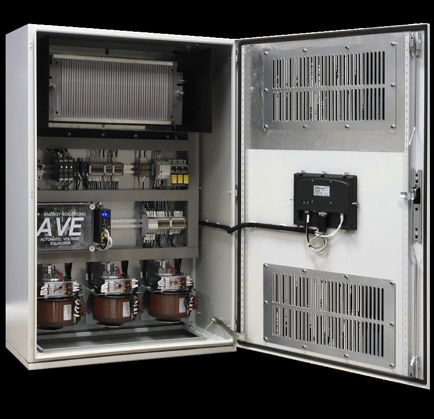
Automatic Voltage Equalizer
•   Based on unique electromagnetic technology
•   Eliminates transients and surges
•   Voltage balancing
•   Prevent Arc-Flash
•   Reduced energy consumption
•   Extended lifespan of electrical components
•   Reduce voltage harmonics (Phase – Ground)

AVE Hybrid
•   Ultimate solution - Controls both voltage and current
•   Mitigates harmonic current and voltage
•   Current and voltage balancing
•   Reactive power compensation (PFC)
•   Eliminates transients and surges
•   Compliance with IEEE519 , IEC61000+++
•   Reduced supply sags & swells

APF - Active Power Filter
•   Eliminate harmonic distortion
•   Power factor correction
•   Sags & Swells reduction
•   Load balancing
•   Flicker mitigation
•   Energy savings
•   Extended equipment liftetime

Static VAR Generators
•   Dynamic step-less compensation
•   Power factor correction of 0.99 lagging or unity if required
•   Eliminates the need for switched capacitors
•   Corrects load imbalance
•   Eliminates transients and surges
•   Mitigation of 3rd, 5th, 7th, 11th harmonic orders (ASVG)
•   Unit capacity can be shared 50/50 (PFC/THD) (ASVG)

                                                                   1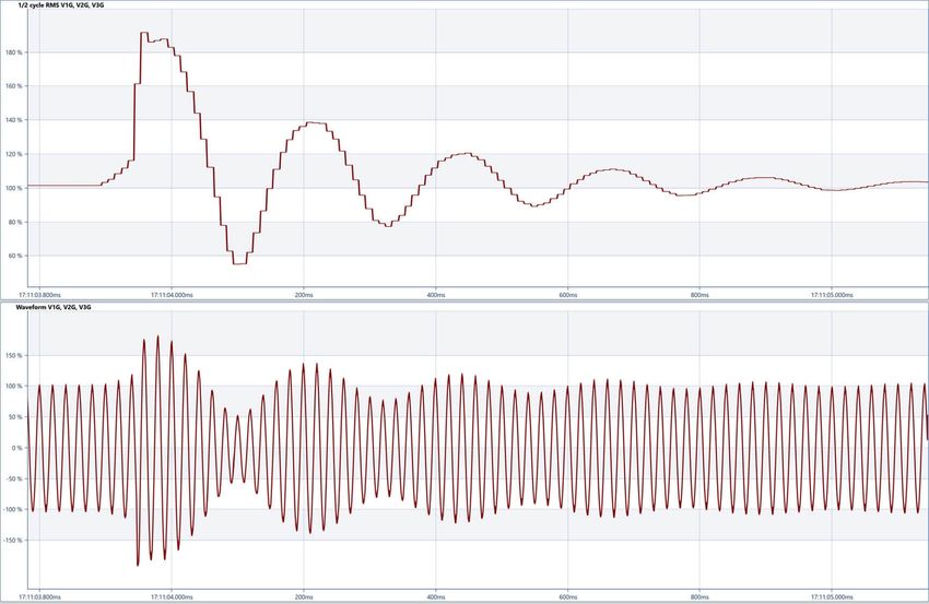
Power Quality
                                                                                             General
The term ‘Power Quality’ is used to describe the quality or ‘fitness’ of electric energy that drives an
electrical load, and the power quality dramatically affects the load’s ability to function properly. Wit-
hout adequate power quality, an electrical device may malfunction, fail prematurely, or not operate at
all.

The power grid’s ability to supply a clean, continious, and stable power flow together with
the amount of noise the load creates defines the power quality situation of the plant. The voltage and
current flow should ideally have a pure sinusoidal waveform while remaining within specified am-
plitude and frequency tolerances. Unfortunately, no real-life power source is ideal, and power quality
related problems are always present to some extent.

In today’s electrical networks, substantial deviations from ideal conditions are frequent due to inter-
nal factors like an increased amount of non-linear loads or external factors like a weak power grid,
among many more. Power generation is also becoming more involved with new players and techno-
logies entering the business, which adds new challenges to power grid operators.

The consequences of insufficient power quality can be severe losses on business and economy. In
a worst-case scenario, it may even pose a threat to human life in mission-critical applications and
highly sensitive environments, such as hospitals.

Does poor power quality contribute to additional costs other than just an increased electricity bill?

Yes, and these additional costs are a reality in many industries. The cost of power quality problems
can be directly related to increased energy consumption but also hidden costs such as downtime, loss
of production, equipment damage, idling personnel, data losses, negative impact on cash flow, custo-
mers, and marketing value.

Even though we think that the power quality is within recommended standards in most European
countries and the United States, poor power quality is, in fact, a severe, increasing problem.
The direct and hidden costs of poor power quality are high, and the annual cost is estimated to be
119$ – 188$ billion for U.S. companies and 150€ billion for European industry.

 2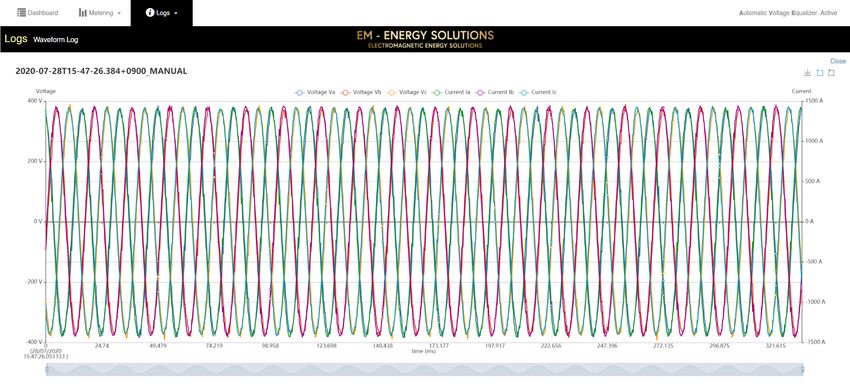
Power Quality
                                                                                           Examples
Examples of power quality problems:

Power Outages:
The expense of a power outage implies more than just the cost of lost kWh during normal operation.
One 60 min outage during a year is usually much cheaper than 1 min outage 60 times a year.

Dips, sags, swells, surges:
If the voltage decreases or increases below/above a specific limit for a short time, it causes interrupti-
ons and damages in control systems, which leads to problems in electrical systems.

Harmonics:
Harmonic distortion can cause sporadic problems. Harmonics have different impacts such as voltage
waveform distortion, efficiency losses, failures in compensation systems, failures in sensitive electro-
nic devices, overheating in electric motors, and transformers.

Power imbalance:
The current imbalance has two main effects: a higher peak demand in one phase, which can lead to
heat losses, and over dimensioning of the feeder. At the same time, a current imbalance creates volta-
ge unbalance when going through the feeder. Voltage imbalance can make, e.g., VSD control system
unstable.

Arc-Flash:
Arc-Flash is one of the most dangerous electricity-related incidents for both personnel and equip-
ment. It is an electrical explosion/discharge that results from a low-impedance connection through
the air to ground or another high voltage phase in the electrical system. It can be initiated through
accidental contact, underrated equipment compared to available short circuit current, contaminated
insulated surfaces, as well as other causes. According to Industrial Safety and Hygiene News report,
there are on average 30 000 Arc-Flash incidents every year with an estimated 7000 burn injuries,
2000 hospitalizations, and 400 fatalities.

Ground fault:
Ground fault is an unintentional contact between a live conductor and ground potential, that will
result in a fault current flowing through either the grounding system or any other personnel or equ-
ipment. Ground faults are potential life threatening dangers when they are left untreated and become
a live hazard for personnel and animals.

Transients:
A transient event is a short lived burst of energy in the power system, often seen as voltage spikes
with various amplitudes. These Spikes will, depending on their size and time duration, damage or
even destroy electrical equipment.

                                                                                                     3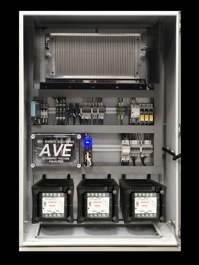
Power Quality
                                                                                          Examples
Voltage sags
The definition of a voltage dip according to the IEC 61000-4-30 standard, is a slight reduction in
RMS voltage of 10 percent or more below the nominal voltage for a period of more than ½ cycle to
one minute. Voltage dips are a common power quality occurrence several times per year at an indus-
trial plant’s common point of coupling or other locations in the plant’s power system. Recent years
power quality standards like the IEEE 1668 published in 2017 (recommended Practice for Voltage
Sag and Short Interruption Ride-Through Testing for End-Use Electrical Equipment Rated less than
1000V), have brought on requirements for electrical equipment to ride through short voltage dip
events.

Graph displaying voltage sag in both RMS and Waveform value

What is causing voltage Sags?
The major cause of voltage Sags on a supply system is a fault on the system, that is sufficiently remote
electrically that a voltage interruption does not occur. Other sources are the starting of large loads
(especially common in industrial systems), and, occasionally, the supply of large inductive loads.
Faults on a supply network occur, and in industrial systems it is often practiced to specify equipment
to ride-through voltage dips of up to 0.2s. The most common exception is contactors, which may
well drop out if the voltage dips below 80% of rated voltage for more than 50-100ms.
Other network-related fault causes are weather-related (such as snow, ice, wind, salt spray, dust),
causing insulator flashover, collisions due to birds, and excavations damaging cables. The impact
on consumers may range from the annoying (non-periodic light flicker) to the serious (tripping of
sensitive loads and stalling of motors). Where repeated dips occur over a period of several hours, the
repeated shutdowns of equipment can give rise to serious production problems.

 4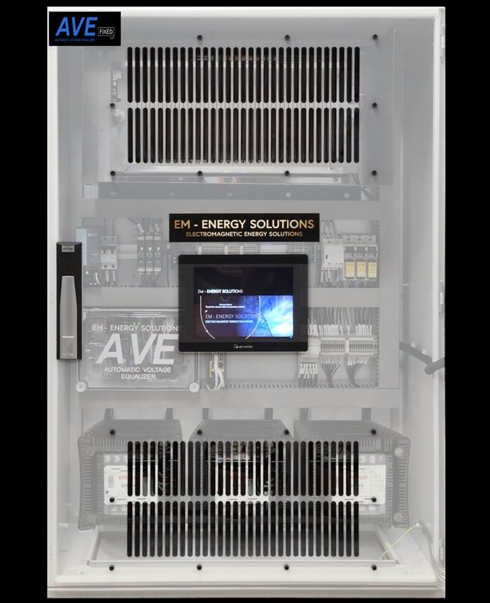
Power Quality
                                                                                          Examples
Voltage swells:
As the name implies, this is the opposite of voltage dips, defined by the IEC 61000-4-30 standard as
a brief increase in RMS voltage of 10 percent or more above nominal equipment voltage for a period
of ½ cycle to one minute. Voltage swells are usually associated with system fault conditions - just like
voltage sags, but are much less common. This is particularly true for ungrounded or floating delta
systems, where the sudden change in ground reference results in a voltage rise on the ungrounded
phases. In the case of a voltage swell due to a single line-to-ground (SLG) fault on the system, the
result is a temporary voltage rise on the healthy phases, which last for the duration of the fault.

Voltage swells can also be caused by the de-energization of a very large load. The abrupt interruption
of current can generate a large voltage, per the formula: V = L di/dt, where L is the inductance of the
line, and di/dt is the change in current flow. Moreover, the energization of a large capacitor bank will
also cause a voltage swell, though it more often causes an oscillatory transient.

Although the effects of sag are more noticeable, the effects of a voltage swell are often more destru-
ctive. It may cause a breakdown of components on the power supplies of the equipment, though the
effect may be a gradual and accumulative effect. It can cause control problems and hardware failure
in the equipment due to overheating that could eventually result in a shutdown. Also, electronics and
other sensitive equipment are prone to damage due to voltage swell.

Graph displaying voltage swell in both RMS and Waveform value

                                                                                                   5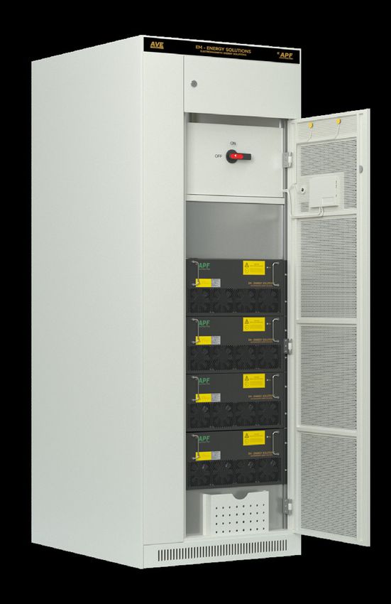
Power Quality
                                                                          Harmonic Distortion
Harmonic distortion is an increasing problem in today’s modern electrical system. The rapid uptake
of sophisticated power electronics devices and non-linear loads has resulted in electrical networks
that are rich in harmonic currents and voltage distortion.

Non-linear loads draw current from the electrical supply that is non-sinusoidal. These currents
contain additional components referred to as harmonic currents, which are at frequencies multiples
of the fundamental frequency. In situations with significant current harmonics in conjunction with a
high impedance weak distribution system, significant voltage harmonics also occur.

The total harmonic distortion voltage THDv is the measurement of the distorted voltage waveform.
The measurement of the current waveform, including the fundamental and harmonics, is described
as the Total Harmonic Distortion Current or THDi.

Typical Non-LinearLoads:

•       Uninterruptable Power Supplies (UPS)
•       Induction Furnaces & Welding Machines
•       AC and DC Variable Speed Drives
•       Battery Chargers and other DC Supplies
•       LED and Fluorescent Lighting Circuits
•       Computers and other devices containing Uncontrolled Rectifiers

WHY REDUCE HARMONICS?

Harmonic currents increase the level of current drawn from the supply and affect the quality of
the supply voltage. Electrical networks operate at the fundamental frequency, and the presence of
currents with a frequency different from the fundamental stresses distribution equipment and can
disrupt normal power supply operation. Some typical effects of harmonics are:

•       Overheating of transformers, switchboards, cables, and motors due to increased current flow.
•       Nuisance tripping of thermal protection devices such as overloads and circuit breakers
•       Overloading of neutral conductors
•       Poor Power Factor & premature failure of PFC capacitors
•       Failure of PLC, DCS, computer, and other sensitive low voltage power supplies
•       Premature failure of motors and poor motor performance

Harmonic currents can be improved by installing Active PowerFilter (APF) equipment. APF equip-
ment simply adds currents 180 degrees out of phase with the existing harmonic currents, but that are
equal in magnitude and frequency.

    6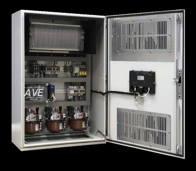
Power Quality
                                                                        Harmonic Distortion
High precision process control in today’s modern industry relies on electromotors controlled by
variable frequency drives, otherwise known as VFDs. These VFDs contain state of the art IGBT
(Insulated Gate Bipolar Transistors), that together with a controller, enable accurate speed/frequency
control of the motor and subsequent machine.

A VFD works by having a rectifier section at the input that generates DC voltage supplying an in-
ternal DC bus. The inverter section at the output side provides the Pulse Width Modulated (PWM)
waveform. A VFD changes the speed of the motor by altering the frequency of the voltage supplied
to the motor.

PWM is employed to control the voltage and frequency supplied to the motor drive. DC voltage is
applied to the motor by controlled pulses at high frequency, which results in a voltage that approxi-
mates a sine wave of the chosen frequency.

This PWM method creates harmonics in the system. The switching also creates radio frequen-
cy interference (RFI) and voltage spikes that can be up to 1200V at the motor terminals. The high
switching frequency can also lead to ’capacitive bearing currents’ that flow through the motor bea-
rings and can damage the bearing surfaces. A portion of the harmonics is reflected in the VSD by the
motor, creating further issues in the electrical environment.

Harmonics in an electrical system can cause:
• Degradation of motors, especially the bearings and insulation = higher costs
• Significant reduction of the lifespan of equipment due to excessive heat = higher costs
• Although you get billed for the supplied power, a large percentage of that power may be unusable
   = higher costs
• Unusual events such as flickering lights, alarms going off, or MCBs, MCCBs, RCDs and Earth
   Leakage devices tripping for no apparent reason = more downtime = higher costs

VFDs are prolific creators of harmonics in electrical systems, and as a result, most of the harmonic
mitigation effort focuses on the input side and output side of a VFD. For the mitigation of harmonics
on the input side (line side) of a VFD, we recommend Active Power Filters. For the mitigation of
harmonics on the output side (load side) of a VSD, we recommend our AMO/AMO-SF units.

                                                                                                  7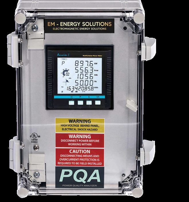
Power Quality
                                                                          VAR Compensation
Power losses due to low power factor

If the plant is operating with a power factor of 0,6, it means just 60% of the consumed power is used
effectively and that 40% is being wasted. The 40% that is being wasted consists of reactive power.
Many industrial loads have inductive characteristics bringing the power factor away from unity. The
lower the power factor, the larger the apparent power drawn by the system. The increased apparent
power draw causes an increased current draw. The increased current draw puts extra load on the
utility system, transformers, and the plant itself. This additional current draw causes additional ener-
gy costs and limits the utilization of available grid capacity.

Why improve the power factor?

Low power factor gives penalties to you as a consumer, because of the extra strain and costs it gives
the utility supplier. By improving the power factor, less current is consumed by the system and plant
operator, and utility suppliers benefit from it in terms of reduced energy consumption, and costs.

What is Power Factor Correction technology?

Conventional power factor correction technology has been based on capacitor banks for storing and
supplying reactive power. These are inaccurate systems in terms of adapting to the actual reactive
power consumption of the plant. Also, they are large in size and not very space-effective. EMES pro-
vides the latest high-performance technology with simple installation & commissioning. Our units
have a compact design and are very space-effective.

What will you achieve with unity power factor?

An electrical system with an unsatisfactory power factor consumes more current than a system with
improved power factor for the same amount of useful power transferred. This additional consumpti-
on causes unnecessary load on the electricity distribution network. By optimizing the power factor,
your electricity bill is reduced due to lower monthly demand and capacity charges. Typically payback
time for our power factor technology is between 1-3 years. Taking into account the life expectancy of
the power factor correction equipment and potential savings, it is a cost-effective investment.
Low power factor results in energy losses and voltage drops, which in turn contributes to excessive
equipment heating and malfunction of motors and other electrical equipment. If the electrical sys-
tem has reached its maximum capacity, installation of power factor correction equipment would help
avoid costly upgrades by reducing the existing system demand and improving efficiency.

 8
Power Quality
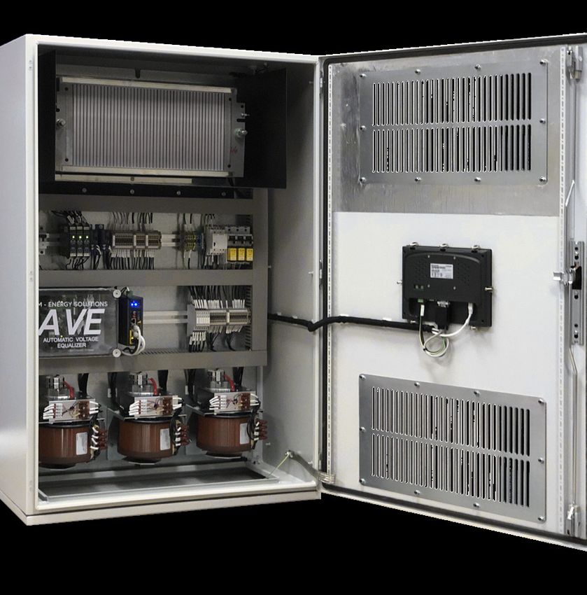
AVE control cabinet
AVE - EMP protection
Problems related to frequency distortion are complex and is in most situations generated in the
end user’s power system. These issues can vary from harmonics, transients, notching, voltage sags
& swells, to other power quality-related issues that alter the frequency away from the fundamental
frequency.
End-users connected to weak distribution systems with high impedance and low short circuit capa-
city are more prone to these internally generated harmonic distortions, especially wye distribution
systems containing a neutral conductor.
In terms of vast interconnected grid failure caused by frequency distortion, the cause can either be
natural events like solar storms or an enemy attack (EMP). Solar storms can be hard to predict and
can cause massive blackouts throughout a grid and subsequent collateral damage by damaging key
power infrastructure components.
Solar storms vary in severity and direction and are a release of high amounts of magnetic energy
from the sun’s surface that propagates through space and collides with the earth’s magnetosphe-
re. A solar storm massive enough in scale could cause billions of dollars’ worth of damage to radio
communication, satellites, or power grids, that could take weeks or months to repair.
Similarly, an EMP can have the same effect as a solar flare but initiated by an enemy attack genera-
ted by a high-altitude nuclear explosion. By targeting key infrastructure components, a vast amount
of populated areas can suffer power grid blackouts, causing massive havoc. The nuclear explosion
creates a high-frequency electromagnetic field within the vicinity of the detonation point. This field
can be strong enough to produce transient voltage spikes of thousands of kilovolts. These transients
can severely damage or even destroy transformers, generators, radios, radars, computers, and other
electrical equipment.
9Power Quality
EMP Theory
These EMP induced voltage spikes are not unlike the effects of a lightning strike, and computer
based processing, communication, automotive, communication, electronic flight control, satellite,
and warfare communication systems are all vulnerable to the EMP effect. Modern technology is even
more vulnerable to EMP attack since solid-state equipment used today is more susceptible to damage
by large, brief voltage and current surges compared to older vacuum-tube based equipment.
In terms of military equipment, which contains a vast amount of electronic equipment, an EMP atta-
ck can severely reduce their functionality or even destroy them without sufficient safety measures.
The AVE mitigates these high-frequency disturbances, which present themselves as zero sequence
components in the power grid. The AVE filters the harmonic components with the square of the
order of the harmonic. This square factor implies that a 7th order harmonic is filtered 49 times. The
unique design of the AVE makes it capable of reducing harmonic components from the 2nd order up
to very large orders by merely beating the noise against itself. The AVE is not limited to specific fre-
quencies or amplitudes, unlike today’s technology for mitigating high-frequency noise or harmonics,
like passive and active filtering systems.
10Power Quality
AVE transient mitigation
AVE mitigates harmonics with the speed of the electromagnetic field, which makes it extremely use-
ful in mitigating EMP induced transient, which often lasts for only a few microseconds. The figure
below describes how the AVE mitigates transient voltage spikes. A voltage imbalance can present
itself as a transient voltage spike, zero-sequence harmonic, steady-state voltage imbalance, notching,
or any other power-quality related event that alters the phase to ground voltage. In theory, the events
can occur at many different frequencies up to the EMP frequency range area.
A voltage potential is set up across the circuit’s secondary side steel grid resistor when an imbalance
in the voltage occurs. This potential means a current starts to flow, and energy from the transient
dissipates in the steel grid resistor. Also, energy is redirected back into the low voltage phase to even
out the phase to ground voltages. The amount of energy redirected back into the low voltage phases
is dependent on system impedance.
The figure visualises how the AVE mitigates transient voltage spikes
11Power Quality
EMP Pulse
If we look at typical electromagnetic pulse shapes, we see that a nuclear EMP transient is exceptio-
nally brief in time, lasting only a few microseconds. The figure below clearly shows how fast an EMP
transient is compared to a lightning strike or flux compression transient.
Timespan and amplitude of EMP, ligthning and flux compression transient event
12Power Quality
MOV based technology
Conventional protection technology based on metal oxide varistors often referred to as surge pro-
tection devices, better known as SPDs are very sensitive to high voltage transients, and are easily
damaged. Also, they are too slow to react and allow voltages 4-5 times the nominal voltage rating
into the equipment they are meant to protect. The graph below shows how semiconductor protection
technology is too slow to stop transient voltages before they can do damage to the equipment.
MOV based technology allows 4-5 times nominal voltage onto equipment it is meant to protect
13Power Quality
AVE installation location
To protect your power system from all of the power quality related problems mentioned in this
document, one AVE per distribution system is sufficient. The AVE is placed on the secondary side of
the distribution transformer, with no more than 15 meters of wire between connection points. The
connection diagram below shows how the AVE is connected to a TN-C-S distribution system.
AVE connects in parallel on distribution transfomers secondary side
14Automatic Voltage Equalizer
AVE control cabinet
AVE - Automatic Voltage Euqalizer
EM Energy Solutions’ revolutionary patented technology for voltage stabilizing ensures an optimal
phase voltage balance on both grounded and ungrounded distribution systems.
AVE is an EHRGS (Electromagnetic High Resistance Grounding System) that reacts to any voltage
imbalance and equalizes the voltage between all phases with the speed of the current.
By constantly logging the supply transformers’ phase to ground voltages and using this to control
single-phase variable or multitap transformers, one can achieve optimal phase voltage balance. A
state-of-the-art controller controls the variable transformers. The system has an operator panel for
control functions and display of operational status together with a comprehensive alarm system that
will notify operators about various events like ground faults, transients, and high harmonic distorti-
ons.
AVE serves as a surge suppressor, voltage regulator, and zero-sequence harmonic filter. It is easy
to install and is connected as close as possible to the transformer secondary side. It will protect all
downstream equipment, thus making other power quality technology such as MOV based devices
unnecessary and obsolete. By having the AVE installed, the result will be substantial cost savings and
increased electrical safety.
Key features
• Balanced Voltage; AVE will keep the voltage • Increased plant safety
balanced and phase vectors perfectly 120 degrees offset • Simple and fast installation
• Mitigates transient events; The larger the transient, the more • Arc-Flash mitigation; AVE will reduce Arc-Flash
AVE will counteract it potential by more than 85 percent
• Reduction in Zero-Sequence harmonics • EMP protection
• Reduction in energy consumption • Reduced CO2 emissions
15Automatic Voltage Equalizer Diagram showing working principle of the AVE Here you can see a simplified schematic of AVE’s main circuit. The variable transformers are connec- ted in wye configuration on the primary side with neutral connected to ground, while the secondary sides of the variable transformers are connected in delta-series with a stainless-steel grid resistor. The schematic visualizes the current flow in the AVE during a ground fault. The working principle will be the same for any other voltage imbalance related problem. If we look at the phase vector display, we see that the voltages are ideally 120 degrees offset during the fault. The two healthy phases (L1 and L2) support the low voltage/faulted phase (L3). Energy is redirected from the healthy phases to the low voltage phase through the transformer circuits’ secon- dary side and will cause an increase in voltage on the low voltage phase. During the fault, all phase currents will be in phase, making us able to use simple mathematics to calculate the ground current (See equation for I_gnd in the schematic). 16
Automatic Voltage Equalizer

                AVE Fixed control cabinet

                                   AVE - Fixed
AVE Fixed is a more cost friendly solution but can still pack a punch. It uses fixed high-quality iso-
lation transformers with variable tapping regulated by a controller. It will make an instantaneous co-
rrection to any phase voltage imbalance. Any steady-state voltage imbalances will be corrected with
the variable tapping functionality, making it capable of correcting 100% voltage imbalances (fault
condition).
Due to its robust design transformers, the unit requires very little maintenance. It comes with an
integrated power quality meter with access through a remote web server and cloud solution. Control
and status information from the unit can also be obtained from the local HMI panel.

                                                                                                  17
Automatic Voltage Equalizer
AVE mini control cabinet
AVE - Mini
AVE-mini is a more cost and space-effective solution for lower range transformers between 400
to 1200 kVA. The same electromagnetic principles as used on the standard AVE are applied. The
compact design reduces the challenge in terms of available space. It is fitted with high-quality sin-
gle-phase transformers utilizing controller regulated variable tapping to achieve voltage balancing to
a high degree of accuracy.
The unit has the integrated power quality meter as optional. The operator can obtain necessary sys-
tem information from the HMI panel located in the front door. AVE-mini also comes in single phase
solutions, making it suitable for smaller housing areas.
18Automatic Voltage Equalizer
AVE High Voltage Control Cabinet
AVE - High Voltage
AVE High Voltage is designed for voltages up to 15000 volts. The unit is fitted with single-phase iso-
lation transformers with controller regulated variable tapping. The AVE High Voltage will be custom
sized for each installation, ensuring optimal sizing for the specific transformer energy rating and
voltage class.
Due to its robust design, the unit requires very little maintenance. When installed in front of a smal-
ler sized transformer, it will protect downstream transformers from external events like lightning
strikes, short circuits, and phase voltage imbalances.
19Automatic Voltage Equalizer AMO in conjunction with VFD and motor AMO - Automatic Motor Optimizer The Automatic Motor Optimizer is designed for protection of frequency-controlled motors. Harmo- nics and voltage spikes from frequency drives create a wide range of problems like reduced motor efficiency and drastically shortened motor life expectancy. These problems also limit the allowed cable length between motor and VFD. With the AMO installed, a significantly increased cable length is allowed between VFD and motor. The AMO extends motor life by balancing phase to ground voltages, allowing the drives and control system to operate reliably. The AMO is also suitable for use on smaller-scale distribution transfor- mers up to 400kVA. In situations where available space for installation is a challenge, and the trans- former sizes are small, the AMO is the perfect match. 20
AVE - Hybrid

                Hybrid Control Cabinet             AVE Control Cabinet

                                  AVE - Hybrid
AVE Hybrid is the ultimate solution to any power quality related problem. Combining the AVE
technology with our active units ensures optimal power quality in your plant. The active part of the
hybrid solution ensures the removal of system harmonics, load balancing, and a power factor close to
one. The AVE part mitigates fast switch transients and protects the installation against voltage surges.
The unit also reduces voltage dips and its effects together with reducing zero-sequence harmonics,
ensuring a clean and stable ground reference, which again will reduce the risk of control system loc-
kups. The AVE - Hybrid gives longer equipment lifetime, higher process reliability, improved power
system capacity and stability, and reduced energy losses, complying with most demanding power
quality standards and grid codes.

Key Features
• The ultimate solution to ensure an optimal power •       Unique 3-level topology based on a zero
  quality by controlling both current and voltage.         voltage transformation design and incor-
• Provides Reactive Power (PFC) & Load Balancing           porating high-frequency inductor techno-
• Transient and Surge suppression                          logy results in more than 97% efficiency.
• Harmonics Compensation Capability: Compen- •             User-Friendly Interface and Monitoring
  sates 2nd to 50th harmonic order or simultaneous •       Very easy to operate. Online monitoring
  compensation of all 50 harmonic orders.                  and programming available. Presents infor-
• Algorithm Intelligence: Intelligent technology that      mation in terms of numerical data, wave-
  integrates both FFT and Dynamic Compensation             form analysis, etc.
  modes, customized to client’s requirements.         •    Modular, Compact Size and Light Weight
• Simple Installation & Commissioning (‘Plug and •         Can be wall mounted and installed in small
  Play’)                                                   spaces.
                                                      •    Standards: IEC61000 / IEC60146 /
                                                           EN55011 EN50091 / IEEE519

                                                                                                   21
AVE - Hybrid
Combined functions AVE / Active Units
By combining the AVE and Active unit technology, the AVE-Hybrid is capable of controlling both
current and voltage, making it capable of addressing almost all known power quality related pro-
blems we see today.
AVE-Technology
The AVE is an EHRGS (Electromagnetic High Resistance Grounding System) that reacts to any vol-
tage imbalance and equalizes the voltage between all phases with the speed of the current.
By constantly logging the supply transformers’ phase to ground voltages and using this to control
single-phase variable or multitap transformers, one can achieve optimal phase voltage balance. A
state-of-the-art controller controls the variable transformers. The system has an operator panel for
control functions and display of operational status together with a comprehensive alarm system that
notifies operators about various events like ground faults, transients, and high harmonic distortions.
AVE serves as a surge suppressor, voltage regulator, and harmonic filter. It is easy to install and is
connected as close as possible to the transformer secondary side. It protects all downstream equip-
ment, thus making other power quality technology, such as MOV based devices unnecessary and
obsolete. By having the AVE installed, the result is substantial cost savings and increased electrical
safety.
Key features AVE
• Balanced Voltage; AVE keeps the voltage • Increased plant safety
balanced and phase vectors 120 degrees offset • Simple and fast installation
• Mitigates transient events; The more extensive • Arc-Flash mitigation; AVE reduces Arc-Flash
the transient, the more AVE counteracts it potential by more than 85 percent
• Reduction in Zero-Sequence harmonics • EMP protection
• Reduction in energy consumption
AVE control cabinet
22AVE - Hybrid
Combined functions AVE / Active Units
Active unit technology
The active part of the AVE-Hybrid either contains APFs, SVGs, ASVGs, or a combination of these
units, enabling a tailor-made solution for optimal performance and cost-effectiveness.
EMES Active units are the ultimate answer to power quality problems caused by waveform distor-
tion, low power factor, voltage fluctuations, and load unbalance. It is a high performance, compact,
flexible, modular, and cost-effective solution that provides an instantaneous and effective response
to power quality problems in both low and high voltage power systems. The unit connects in parallel
with the power grid and detects the harmonic components with the help of current transformers. An
advanced algorithm generates a reverse-phase compensation current, which by the help of IGBTs are
injected into the power system to cancel out the harmonic distortion.
The EMES Active Units contains an algorithm that balances the load current on the individual phase
by redirecting excessive load current back into the phases with less load. This function keeps a balan-
ced loading on the supply side. The unit uses excess capacity for additional reactive power compen-
sation and power factor improvement. Configurable priority mode is also available, which enables
the operator to choose if the remaining capacity is used for load balancing or power factor impro-
vement.
Load balancing principle SVG
Key functions APF Customer benefits
• Elimination of harmonics • Energy savings
• Lagging or leading power factor correction • Higher productivity
• Voltage sags & swells reduction. • Reliable operation at reduced maintenance costs
• Voltage fluctuations (flicker) mitigation. • Longer lifetime of electrical and process equipment
• Load balancing in three-phase systems. • Additional capacity in an existing electrical network
• Selectable harmonic mitigation • Compliance with IEEE 519, G5/4, IEC 61000 3-2, 3-4
or any other power quality standard
• Quick return on investment
23AVE - Hybrid
Benefits
According to a European study made by Manson & Roman Targosz, the total cost of bad power qua-
lity in Europe alone is 150B euros per year. The diagram below displays the various causes and their
part of the total cost.
29% Transients and surges
24% Voltage dips
19% Short interruptions
5% Harmonics
11% Others
12% Long interruptions
Study done by Manson & Roman Targoz estimates 150B euros in power quality costs per year in Europe alone
By having the AVE Hybrid installed, you can protect your plant against more than 88% of these
problems and subsequent costs (AVE Hybrid AVC). Depending on the power quality situation, the
hybrid solution can be delivered with either APF, SVG, ASVG or a capacitor bank in conjunction
with an APF solution.
APF Operational Principle APF Control Cabinet
24AVE - Hybrid
Standard hybrid models
Here is a brief summary of the various standard hybrid models available. Other variants are also
available based on what will be the optimal solution for your plant.
AVE Hybrid SVGC
The AVE Hybrid Static VAR Generator Capacitor is a more cost-effective solution. The cost reducti-
on is achieved by using a capacitor bank to take the central portion of the VAr compensation. At the
same time, the active filter compensates for the intermediate steps and the inductive reactive power.
Also, the active filter works as a load balancer and a harmonic filter. The integrated AVE technology
protects against transient voltage surges and dips together with zero-sequence harmonics.
In combination with our revolutionary AVE technology, this is an all-in-one, cost-effective solution
for optimized power quality and:
• Cost-effective and fast power factor correction
• Harmonic current and zero-sequence harmonic voltage mitigation
• Load balancing
• Voltage surges and dips protection
25AVE - Hybrid
Standard hybrid models
AVE Hybrid AVC RTS/DVR
The AVE Hybrid Active Voltage Conditioner unit combines filter technology, AVE hybrid techno-
logy, UPS technology, or voltage regulator technology into one package. The unit comes with two
options in terms of blackout prevention; either an energy storage system that allows for higher power
outage ride-through times (AVC RTS) or with voltage vector control for smaller voltage ride-through
times (AVC DVR).
The AVC DVR is a more cost-effective solution than the AVC RTS but still compensates for up to
40% voltage variation for up to 30 seconds. The RTS is based on thyristor controlled ultra-capacitor
banks with superior power density, cycle life, and life-expectancy for higher ride-through capacity.
Both units protect your installation from power outages, interruptions, and voltage dips, while the
AVE and filter technology protect against transient voltage surges, harmonic current distortion,
zero-sequence voltage harmonics, and flicker. The units also perform load balancing.
The Hybrid AVC has the possibility for two operational modes (optional). During a stable power
supply, it operates in power quality mode performing harmonic current mitigation, load balancing,
and flicker mitigation. When a power outage or voltage sag is detected, the unit switches from power
quality mode to power supply mode, securing power to the plant and preventing the effects of the
voltage sag or power outage. The units are available in load capacities between 150kVA to 3000kVA,
with higher ratings available on request.
With AVC RTS hybrid installed, the power system can ride through power outages for up to 3
seconds as standard. The 3-second limit is based on common industry standard, but other compen-
sating time frames are possible based on system load and capacity of the energy storage system. The
unit has high efficiency due to its intelligent switchover between the operation modes and provides
substantial cost savings compared to conventional technology. The AVE technology will, at all times,
protect against transient voltage surges, zero-sequence harmonics, and is not affected by the operati-
onal mode.
Compared to the AVC RTS, the AVC DVR is not relying on capacitors to counteract voltage sags &
Swells. The lack of capacitors makes this is a more cost-effective solution, but it still compensates for
up to 40% voltage variation for up to 30 seconds, which prevents the effect of sags & swells in most
cases. During regular operation, the AVC DVR optimizes the output power. During a voltage sag, the
AVC boosts the output voltage by altering the voltage vectors to compensate for the reduced voltage.
26AVE - Hybrid
Network Analyzer and Remote Access
The AVE - Hybrid is equipped with one of the most advanced power quality analyzers on the market
today. Data from the unit is reachable through a SCADA network or remotely through a webserver.
There is also a local HMI display for both AVE and active unit for“in the field” troubleshooting and
power analysis.
AVE-Hybrid is standard equipped with industrial Modbus TCP/IP communication protocol wired
or wireless for seamless integration into any existing SCADA system. Other communication pro-
tocols are also available HTTP/HTTPs Post, FTP, sFTP, BACnet-IP, DNP3 V2, SNMP V3, IEC61850
2nd edition, SMTP.
WEBSERVER
The PQA`S Ethernet module supports HTTP protocol and has a Web Server function making the
PQA accessible through Ethernet or 4G router anytime from anywhere. (4G Router is optional)
Fully encrypted and authentic data communication between PQA and data server. Leading HTTP
web security standard TLS v1.2 and SSL HTTPS encryption. WPA or WPA2 enterprise security pro-
tocol authenticates the WIFI communication. The PQA also has inbuilt storage for realtime energy
logs, waveform capture, and data logs.
WAVEFORM & FAULT RECORDER
The PQA (Power Quality Analyzer) allows trigger point waveform recording. This function ena-
bles operators to go back and look at any situation that has taken place to understand the sequence
of events in the power system. The meter supports a waveform capture function that allows users
to capture and record 10 cycles before and after the triggering point, whether it be a voltage sag,
swell, or over current. The waveform log on the web interface allows users to view these waveforms
whenever a power quality event has occurred. The log displays a table that includes waveform files,
timestamps, and file sizes. The waveform file name includes the timestamp when the event occurred
as well as the parameter name/event name that triggered the power quality event.
Trend log taken from Power Quality Analyser
27AVE - Hybrid
Network Analyzer and Remote Access
Functionality Customer benefits
• Harmonic mitigation • Energy savings
• Transient and Surge protection • Higher productivity
• Load balancing • Reliable operation and reduced maintenance
• Flicker mitigation costs
• Leading and lagging power factor correction • Extended lifetime on electrical equipment
• Reduction of voltage sags & Swells • Higher utilization of available capacity
• Ground fault detection • Compliance with IEEE 519, G5/4, IEC 61000
• Reduce zero-sequence harmonics 3-2, 3-4 or any other power quality standards,
• Prevent Arc-Flash and recommendations
• Prevent phase voltage imbalance & instability • Quick return on investment
• Prevent arcing ground faults • Increased revenue
• Provide a good and stable ground reference for • Increased plant safety
power system stability to ensure optimal ope-
ration of control systems without interruption.
EMES Power Quality Analyzer
Waveform log of voltage and current taken from EMES PQA
28Harmonic Filtering
APF Module
APF - Active Power Filter
EMES Active Power Filter is the ultimate answer to power quality problems caused by waveform
distortion, low power factor, voltage fluctuations, and load unbalance. It is a high performance,
compact, flexible, modular, and cost-effective solution that provides an instantaneous and effective
response to power quality problems in both low and high voltage power systems. The unit connects
in parallel with the power grid and detects the harmonic components with the help of current trans-
formers. An advanced algorithm generates a reverse-phase compensation current, which by the help
of IGBTs is injected into the power system to cancel out the harmonic distortion.
Key features
• Mitigates harmonic distortion and keeps THDiHarmonic Filtering
APF Operational Principle
APF Control Cabinet IP54 APF Control Cabinet
30Harmonic Filtering
Key Features
Current transducers measure the total current draw, including current harmonics from the trans-
former. The data is transmitted to an internal DSP and CPU, which contains an advanced FFT
algorithm that extracts the various harmonic current components from the fundamental current.
The IGBT controller uses the data to produce a PWM signal with a switching frequency of up to
35kHz. This data is used in the IGBT controller to produce a PWM signal with a switching frequen-
cy of up to 35kHz. In realtime, internal current transducers register the output current and feed the
signal back to the DSP, and the regulator performs corrections to optimize the harmonic mitigation.
ULTRA-COMPACT FOOTPRINT
EMES’ innovative three-level inverter technology is the foundation of every APF unit. The modular
three-level inverter uses 12 IGBTs to reduce the switching frequency losses and to permit higher
overall switching speed. The three-level inverter technology requires small filter components in
comparison with conventional technology, which provides for an ultra-compact, modular design
with a resulting improved waveform, low levels of harmonic distortion, and electromagnetic interfe-
rence. Multiple EMES APFs can be configured to operate together by simply connecting the external
CTs in series through all the units.
Protection Features
• Internal short-circuit protection • CT installation detection
• Temperature monitoring • Inverter bridge abnormal operation protection
• Over-voltage protection • Inverter over-current protection
• Under-voltage protection • Over-compensation capacity
• Abnormal frequency protection • Component capacity redundancy
• Output overload protection • Fan fault protection
• Busbar over-voltage protection • Fuse protection
31Harmonic Filtering
Intelligent System
EMES APF provides a real-time response with a constant correction to plant harmonics. The virtual-
ly instantaneous response ensures that your plant’s power quality is at the highest possible level, even
with varying harmonic loads.
• Keep THDi below 5%
• Selectable odd and even harmonic mitigation up to 50th harmonic order
• Advanced Fast Fourier Transform for accurate correction of all harmonics up to the 50th order
• Efficiency higher than 97%
• Less than 50 microseconds reaction time with less than 5ms response time
• System impedance at each harmonic component is “learned” by the APF
• Automatic safe-self test mode during the first time startup that gradually increases current mag-
nitude to check system stability.
• Automatically detects resonance frequencies and skips the problem areas.
• Fast and secure wall mount for 5/10/15/25/35/50/60/75/100/150 amp sizes
• Pluggable rack mount option available in 75 amp
• Cabinet mount options for 25/35/50/60/75/100/150 amp sizes
• One cabinet can fit up to 750 amps utilizing any combination of sizes. It is also possible to
combine APF and SVG modules to achieve a more cost-effective solution.
• Increase your capacity as your plant grows, add as many units in parallel as required
Difference between 2-level and 3-level inverter technology
32Harmonic Filtering
Load Balancing and Power Factor Correction
The EMES APF contains an algorithm that measures the load current on the individual phase
and redirects excessive load current back into the phases with less load. This function keeps a
balanced loading on the supply side. Excess capacity is used to compensate for reactive power
and improve the power factor. Configurable priority mode is also available, which enables the
operator to choose if the remaining capacity should be used for load balancing or power factor
improvement.
Load Balancing Principle APF
33Harmonic Filtering
Control and Monitoring
Easy to Use Graphical User Interface
• User friendly graphical user interface
• Direct configuration, monitoring, control, and harmonics analysis
• Communication options, detailed alarm events and fault reporting with real time stamps
Backlit LCD Display
• Incorporates a high level of readability and ease of menu navigation, the LCD display offers:
• Access and configuration of operating parameters
• Measurement data in numerical, graphical and spectrum formats
• Operation status inclusive of detailed alarms and fault messages
• Password protected for critical settings
Measurements
• Provides a comprehensive set of measurement data for analysis, such as:
• Network RMS voltages and currents
• Network Voltage and current distortions (THDu and THDi)
• Total RMS load currents and THDi
• System frequency
• Load factor
• Compensated RMS currents
• Comparison of PF (before and after)
• The graphical waveform of network voltages and currents, load and compensated currents
• Harmonic spectrum for network and load currents, from 2nd to 50th harmonic order
APF HMI layout
34Harmonic Filtering
Modular design
Traditional APFs are large and heavy, often taking up valuable floor space in switch
rooms. EMES have applied new generation thinking and innovative design principles to create a
range of Active Power Filters that feature a modular design and are available in wall-mount, rackmount
and rack/cabinet configurations. This flexibility gives engineers multiple options to cater for all
situations and ultimately save valuable space and ‘floor real-estate’
• Up to 150A capability from a wall-mount solution
• Up to 150A capability from a single rack-mount module
• Up to 500A capability from a single cabinet solution
Plugable Cabinet
Plugable APF control cabinet APF wall mounted module
NOTE: Contact EMES for other available cabinet options
Flexible Cabinet – hardwired modules Pluggable Cabinet - plugged modules
• Up to 750 Amps in • 75A modules only
• 25/35/50/60/75/100/150A modules • up to 525 Amps
• Includes MCCB top or bottom mount. • includes MCCB top or bottom mount
• 600/800/1000 W x 800D x 2200H (mm) • 630W x 851D x 2200H (mm)
• Weight approx. 280kg (empty) • Weight: 210kg (empty)
35Harmonic Filtering
Functions and customer benefits
Key functions Customer benefits
• Elimination of harmonic currents • Energy savings
• Lagging or leading Power Factor correction • Higher productivity
• Voltage sags & swells reduction. • Reliable operation at reduced maintenance costs
• Voltage fluctuations (flicker) mitigation. • Longer lifetime of electrical and process equipment
• Load balancing in three-phase systems. • Additional capacity in existing electrical network
• Selectable harmonic generation • Compliance with IEEE 519, G5/4, IEC 61000 3-2,
3-4 or any other power quality standard
• Quick return on investment
Applications
EMES APF technology is suitable for many industrial or commercial areas where optimal power
quality is a crucial factor for safe and secure operation. The APF technology gives an advantage in
today’s modern industry comprised of variable frequency drives, rapid fluctuating loads such as wel-
ding robots, uninterruptable power supplies, unbalanced systems due to single-phase loads, and arc
furnaces.
• Commercial buildings • Renewable energy • Welding processes
• Data centers & IT • Water and wastewater treatment • Automotive industry
• Airports plants • Printing industry
• Hospitals and laboratories • Heating, ventilation and air condi- • Chemical Industry
• Residential buildings tioning systems (HVAC) • Steel industry
• Shopping malls • Wind and solar farms • Cement industry
• Financial institutions • Traction • Food and beverage industry
• Ski resorts • Metro stations • Oil and gas industry
• Amusement parks • Cranes • Pulp and paper industry
• Marine vessels • Lifts • Textile and clothing industry
• Package sorting facilities • Pharmaceutical industry
• Electronics manufacturers
36Harmonic Filtering
Case Study
The following screenshots display the power quality in terms of harmonic distortion and power
factor in a welding facility at one of the most advanced shipyards in the world. The welding plant was
experiencing excessive harmonic distortion and low power factor caused by the power electronics in
the welding robots. They had previously tried to counteract the problems with conventional capaci-
tor bank technology with unsatisfactory results. We at Electromagnetic Energy Solutions are proud
to say that we were able to bring the power factor close to unity and bring the harmonic distortion
levels to well below the requirements in any power quality standard. THDi dropped from 34% down
to 3%, while the power factor improved from 0,2 (inrush) to near unity. Also, the APF performed
load balancing, causing additional energy savings.
Current waveform distorted by 3rd (4%), 5th (29%), 7th (11%) and 11th (6%) current harmonics. THDi is at 34%, APF is not active
Waveform log of current when APF is active. THDi is now at only 3%, well within any power quality standard
37Harmonic Filtering
Case Study
The illustration below shows the power factor trend from a welding factory. Due to the sampling
rate, the power factor only seems to be dropping down to 0,7, but in reality, due to the fast acting
reactive consumption of the load, power factor drops all the way to 0,2 during welding operation.
During initial startup of each welding sequence, the extreme inrush current draw causes significant
voltage drop, which in turn affects the welding machine and welding quality. After activation of our
APF unit, we clearly see that the power factor remains close to unity and also the voltage drop during
startup is no longer present. This is achievable due to the outstanding response time of the APF unit.
The market leading 35kHz switching frequency, reaction time of 50 microseconds, and overall re-
sponse time of 15 milliseconds, makes the unit capable of realtime response.
7 day trend log showing power factor without APF activated and unity power factor when APF is active
38Power Factor Correction
SVG Module based system
SVG - Static VAR Generator
The EM Energy Solutions SVG represents the latest generation technology in the power factor co-
rrection field. It operates by detecting the load current on a real-time basis through an external CT
(current transformer) and determining the reactive content of the load current. The data is analyzed,
and the SVG’s controller drives the internal IGBTs by using PWM signals to produce and inject the
exact reverse reactive current of the corresponding load reactive content.
Key features
• Excellent power factor correction performance • User-friendly interface and monitoring
• Maintains a PF of 0.99 lagging or unity if required. • Wall-mount & Rack-mount versions
• Compensates both inductive and capacitive loads available
• Corrects lagging and leading power factor. • Can operate at low voltages
• Dynamic step-less compensation profiles the load • Can be used with existing PFC systems
and operates with a response speed ofPower Factor Correction
Operating Principle
The EMES SVG represents the latest generation technology in the power factor correction field.
SVG technology is based on power electronics. It connects in parallel in front of the load that consu-
mes reactive energy or produces harmonic currents, which in turn alters the power factor. The unit
functions as a controllable current source supplying any form of current waveform in realtime.
When the load draws inductive or capacitive current, the total load current turns either lagging or
leading in respect to the voltage, depending on the total consumption. The SVG detects phase angle
distortion and injects leading or lagging current into the distribution system, which brings power
factor back to unity.
SVG Operation modes
For load balancing in 3- and 4- wire systems, the EMES SVG technology uses current control for
rated load capacity. The unity senses the load’s negative sequence current components and, based on
this data, generates the same negative sequence current components in the opposite phase. The result
will be a completely symmetrical load seen from the point of common coupling, which means the
phase voltages and currents will be balanced without active power exchange between network and
SVG.
40Power Factor Correction
Technological evolution
Power Factor Correction systems have come a long way in a short time. Most of the technological
evolution has focused on switching performance of capacitor banks; however, in recent years, advan-
ces in technology have brought active units based on fast switching power electronics to the market.
These units have a significantly faster performance and smaller cabinet footprint compared to con-
ventional capacitor bank technology.
Fixed
compensation
Automatic
switching
Thyristor half
controlled switching
IGTB intelligence
controlled switching
41You can also read