Technical Review of Retrieval and Closure Plans for the INEEL INTEC Tank Farm Facility
←
→
Page content transcription
If your browser does not render page correctly, please read the page content below
PNNL-13651
                                                UC-721

Technical Review of Retrieval and
Closure Plans for the INEEL
INTEC Tank Farm Facility

J. A. Bamberger
B. L. Burks
K. D. Quigley
S. W. Butterworth
D. D. Falter

September 2001

Prepared for the U.S. Department of Energy
under Contract DE-AC06-76RL01830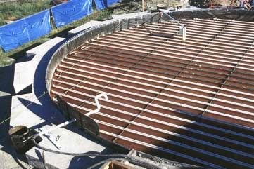
PNNL-13651
                                                                 UC-721

Technical Review of Retrieval and Closure Plans
for the INEEL INTEC Tank Farm Facility

J. A. Bamberger
B. L. Burks(a)
K. D. Quigley(b)
S. W. Butterworth(b)
D. D. Falter(a)

September 2001

Prepared for the U.S. Department of Energy
under Contract DE-AC06-76RLO 1830

Pacific Northwest National Laboratory
Richland, Washington 99352

____________________
(a) The Providence Group Applied Technology
Knoxville, Tennessee 37932
(b) Idaho National Environmental and Engineering Laboratory
Idaho Falls, Idaho 83415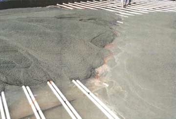
Acknowledgments
     The technical review of the retrieval and closure plans for the Idaho National Engineering and
Environmental Laboratory (INEEL) Idaho Nuclear Technology and Engineering Center (INTEC) tank
farm facility is a part of the Retrieval Process Development and Enhancements (RPD&E) Project under
direction of the US Department of Energy Office of Science and Technology Tanks Focus Area. Funding
for this investigation was provided to Pacific Northwest National Laboratory (PNNL) through the Tanks
Focus Area and to Oak Ridge National Laboratory (ORNL) through the Robotics Crosscutting Program
and the Tanks Focus Area. This work was conducted in collaboration with Keith Quigley and Steve
Butterworth, INEEL at the Idaho Nuclear Technology and Engineering Center.

                                                 iii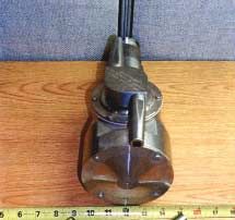
iv

Summary
     The purpose of this report is to document the conclusions of a technical review of retrieval and
closure plans for the Idaho National Energy and Environmental Laboratory (INEEL) Idaho Nuclear
Technology and Engineering Center (INTEC) Tank Farm Facility. In addition to reviewing retrieval and
closure plans for these tanks, the review process served as an information exchange mechanism so that
staff in the INEEL High Level Waste (HLW) Program could become more familiar with retrieval and
closure approaches that have been completed or are planned for underground storage tanks at the Oak
Ridge National Laboratory (ORNL) and Hanford sites. This review focused not only on evaluation of the
technical feasibility and appropriateness of the approach selected by INEEL but also on technology gaps
that could be addressed through utilization of technologies or performance data available at other DOE
sites and in the private sector. The reviewers, Judith Bamberger of Pacific Northwest National
Laboratory (PNNL) and Dr. Barry Burks of The Providence Group Applied Technology, have extensive
experience in the development and application of tank waste retrieval technologies for nuclear waste
remediation.

     This report summarizes INEEL plans for retrieval and closure as of March 2001 and relevant work
performed at the ORNL and Hanford sites. As part of the review process, staff from the INEEL HLW
Program visited ORNL and Hanford for information exchange briefings and tours. The briefing at ORNL
included presentations and discussions of retrieval and closure activities for the Gunite and Associated
Tanks, Old Hydrofracture Facility Tanks, and Federal Facility Agreement Tanks. Retrieval activities
were discussed for the Bethel Valley Evaporator Service Tanks and Melton Valley Storage Tanks. The
ORNL site visit included tours of several tank farm facilities and the Tanks Technology Cold Test
Facility. The Hanford site visit focused on waste dislodging and retrieval technology development and
testing. Discussions included: waste retrieval end effectors, Fernald silo remediation equipment, Pit
Viper, jet dislodging including the West Valley spray ball, Hanford tank U-107 water-spray system,
borehole miner extendible nozzle, leak detection, monitoring, and mitigation, characterization of slurries,
and slurry transport in partially filled horizontal pipes.

    The reviews showed that the INEEL selected technical approach of using a wash ball for removal of
residual waste from tank walls and internal structures with addition of directional nozzles for targeted
cleaning and solids resuspension is both feasible and appropriate given the physical property data
available for the waste heel, properties of the residual waste on the walls and internal structures and
performance data from cold tests performed to date. The grout pouring approach appears to be an
effective means of accomplishing a final heel retrieval while grouting the tank floor.

    It is extremely important to fully characterize the cleaning effectiveness of the selected approach
during the first deployment. Sufficient sampling and inspection should be performed after retrieval is
completed to determine whether more aggressive techniques will be required. It is also important to
determine whether the retrieval process can be modified to reduce overall water usage, reduce cleaning
time, or improve cleaning effectiveness. Attention to the effects of varying flow rates, pressures, traverse
rates, etc. during the first deployment could result in much more efficient and effective cleaning in
subsequent deployments.

                                                     v
vi
Contents

Acknowledgments ...................................................................................................................................... iii
Summary .......................................................................................................................................................v
1.0 Introduction .....................................................................................................................................1.1
  1.1 Background..................................................................................................................................1.1
  1.2 Scope............................................................................................................................................1.1
2.0 Conclusions and Recommendations................................................................................................2.1
  2.1 Technology Synopsis...................................................................................................................2.1
  2.2 Conclusions..................................................................................................................................2.3
  2.3 Recommendations........................................................................................................................2.3
3.0 INTEC Tank Farm Facility Description and Approach to Closure.................................................3.1
  3.1 Tank Farm Details .......................................................................................................................3.1
  3.2 Waste Details ...............................................................................................................................3.2
  3.3 Tank Closure Process Overview..................................................................................................3.2
  3.4 Wash Ball and Directional Nozzle Operation..............................................................................3.4
    3.4.1 Wash Ball .............................................................................................................................3.4
    3.4.2 Directional Nozzle................................................................................................................3.5
    3.4.3 Video Camera.......................................................................................................................3.7
    3.4.4 Riser Interface Adapter.........................................................................................................3.8
    3.4.5 Installation and Operation Sequences...................................................................................3.8
  3.5 Retrieval and Transport ...............................................................................................................3.9
    3.5.1 Variable Depth Steam Jet Pump ...........................................................................................3.9
    3.5.2 Pipeline ...............................................................................................................................3.10
  3.6 Evaluation of Equipment Performance during Mockup Tests...................................................3.11
    3.6.1 Evaluation Summary ..........................................................................................................3.12
    3.6.2 Observations .......................................................................................................................3.12
  3.7 Tank Containment......................................................................................................................3.13
  3.8 Closure.......................................................................................................................................3.13
    3.8.1 Observations .......................................................................................................................3.14
4.0 PNNL and ORNL Technology Exchanges with INEEL .................................................................4.1
  4.1 INEEL Meeting at ORNL............................................................................................................4.1
  4.2 INEEL Meeting at PNNL ............................................................................................................4.1
    4.2.1 Agenda..................................................................................................................................4.1
    4.2.2 Synopsis of Meetings ...........................................................................................................4.3
5.0 PNNL and Hanford Retrieval Technology Development ...............................................................5.1
  5.1 Applicable Jet-Based Waste Dislodging and Mixing Technologies............................................5.1
    5.1.1 Pulsed-Air Mixer ..................................................................................................................5.1
    5.1.2 Pulsating Mixer Pump ..........................................................................................................5.2
    5.1.3 Fluidic Pulse-Jet Mixing.......................................................................................................5.2
    5.1.4 C-106 Sluicer........................................................................................................................5.2
    5.1.5 Borehole-Miner Extendible-Nozzle .....................................................................................5.2
                                                             vii
5.1.6 Waste-Retrieval End Effector...............................................................................................5.2
5.1.7 High-Pressure Scarifier.........................................................................................................5.3
5.1.8 Flygt Mixers .........................................................................................................................5.3
5.1.9 Technology Comparisons and Recommendations................................................................5.3
5.2 Instrumentation and Measurements .............................................................................................5.7
5.3 Recommendations........................................................................................................................5.7
6.0 ORNL Retrieval Technology Development ....................................................................................6.1
6.1 Gunite and Associated Tanks ......................................................................................................6.1
6.1.1 Waste Dislodging & Conveyance System............................................................................6.1
6.1.2 Fluidic Pulse Jet and Flygt Mixers .......................................................................................6.3
6.2 Federal Facilities Agreement Remaining Tanks Project..............................................................6.3
7.0 Lessons Learned from Deployments at ORNL ...............................................................................7.1
7.1 General Project Lessons...............................................................................................................7.1
7.2 Equipment Lessons Learned........................................................................................................7.1
7.2.1 System Design ......................................................................................................................7.2
7.2.2 Grouting System Design and Operation...............................................................................7.3
7.2.3 Operations.............................................................................................................................7.3
7.2.4 Vision Systems .....................................................................................................................7.3
7.2.5 Containment and Maintenance .............................................................................................7.4
7.3 Recommendations........................................................................................................................7.4
8.0 References .......................................................................................................................................8.1
9.0 Distribution......................................................................................................................................9.1
viiiFigures
Figure 3.3 Overview of the tank closure sequence....................................................................................3.4
Figure 3.4 Wash ball showing the dual opposed nozzles..........................................................................3.5
Figure 3.5 Directional nozzle, light, and camera configuration ................................................................3.6
Figure 3.7 Model of steam jet used during retrieval tests .........................................................................3.9
Figure 3.8 View of the entire above ground piping model......................................................................3.10
Figure 3.9 Close up of piping model showing valve contractions in black.............................................3.10
Figure 3.10 Test sequence during tests with wash ball in the test tank...................................................3.11
Figure 3.11 Tank basin showing location of cooling coils......................................................................3.13
Figure 3.12 Pouring grout over the tank bottom to direct fluid to the steam jet entrance.......................3.14
Tables
Table 5.1 Comparison of the waste mobilization technologies.................................................................5.4
ixx
Acronyms

ASME     The American Society of                 SREE   sludge retrieval end effector
         Mechanical Engineers                    SRI    Southwest Research Institute
BOP      balance of plant                        SRS    Savannah River Site
CB       confinement box                         STF    south tank farm
CSEE     confined sluicing end effector          TFA    Tanks Focus Area
DOE      US Department of Energy                 THS    tether handling system
DOF      degrees-of-freedom                      TPG    The Providence Group
DSR      decontamination spray ring              UST    underground storage tank
ECN      engineering change notice               WD&C   waste dislodging and
ER       Environmental restoration                      conveyance
FCE      flow control equipment                  WM     waste management
FFA      Federal Facilities Agreement            WRSS   waste retrieval sluicing system
GAAT     Gunite and Associated Tanks             WTI    Waterjet Technology, Inc.
GSEE     Gunite scarifying end effector
GUI      graphical user interface
HAZWOPER Hazardous Waste Operations
         and Emergency Response
HEPA     High-efficiency particulate air
HMA      hose management arm
HLW      high-level waste
IGAT     intermediate grout addition tank
INEEL    Idaho National Engineering and
         Environmental Laboratory
INTEC    Idaho Nuclear Technology and
         Engineering Center
LDUA     light duty utility arm
LLLW     low-level liquid waste
MET      mast elevation table
MLDUA    modified light duty utility arm
MST      mast storage tube
NEC      National Electric Code
NTF      north tank farm
ORNL     Oak Ridge National Laboratory
PMP      pulsating mixer pump
PNNL     Pacific Northwest National
         Laboratory
RCRA     Resource Conservation and
         Recovery Act
ROV      remote operated vehicle

                                            xi
iv
1.0 Introduction

1.1       Background
    The Department of Energy (DOE) weapons complex is transitioning from production to
environmental restoration (ER). In this process DOE has identified contaminated facilities that are
surplus and need to be decommissioned. These activities must be completed safely, timely, and cost
effectively. In this context, the tank farm at Idaho Nuclear Technology and Engineering Center (INTEC)
has been targeted for closure. The INTEC closure is a high-level waste project that is to be closed in
accordance with DOE Order 435.1 and the Resource Conservation and Recovery Act (RCRA) closure
plan.

    The main focus of the closure is the safe and efficient removal of contamination inside the tanks
before closure. To ensure that this closure is completed safely and efficiently, a proof of process is
underway at Idaho National Engineering and Environmental Laboratory (INEEL). To provide additional
insight into the retrieval aspects of INTEC tank closure, the US DOE EM-50 Tanks Focus Area (TFA) is
providing support to INEEL staff to demonstrate and provide a more complete characterization of the
performance of proposed remediation concepts so that the information can be shared with others facing
similar remediation projects.

    To further support successful remediation, staff at Pacific Northwest National Laboratory and Oak
Ridge National Laboratory were requested to assess the proposed remediation plan being employed at
INTEC to determine whether prior and ongoing research and demonstrations at other DOE sites could be
used as supporting technologies if the proposed plan for INTEC needed to employ more aggressive
remediation techniques.

1.2      Scope
      The project scope is to
         • Evaluate the path proposed for remediation of INTEC WM (waste management) tanks
         • Provide insight and information about more aggressive tank remediation approaches that
             could be applied at INTEC
         • Provide lessons learned from prior demonstrations and deployments that can be applied to
             INTEC tank remediation
         • Summarize the results in a report to provide access to others wishing to consider these types
             of remediation.

                                                    1.1
1.2
2.0 Conclusions and Recommendations
     To support INEEL remediation of the INTEC WM tanks, the US DOE Tanks Focus funded
collaboration between staff at INEEL, PNNL, and ORNL to assess the retrieval and closure technologies
being implemented by INEEL to validate the proposed plan and to provide information about technology
alternatives that could be implemented if retrieval and closure activities uncover unanticipated results.

     To facilitate this activity staff from PNNL and ORNL visited INEEL to review the results of activities
and testing to date and proposed activities. To provide increased understanding about retrieval and
closure development, demonstrations, and deployments at PNNL and ORNL, technical exchanges at each
site were also conducted.

    This report summarizes evaluation of INEEL concepts by staff from PNNL and ORNL and
technology exchanges between PNNL and INEEL staff that visited PNNL and ORNL in April 2001.
Based on these interactions the following observations, conclusions, and recommendations are presented.

2.1       Technology Synopsis
      •   Wash Ball. The wash ball is the primary remediation technology selected for tank cleaning. The
          wash ball nozzles operate at relatively low pressure (0.69 MPa [100 psi]) and a relatively high
          flow rate [0.0047 m3/s (75 gpm)]. In the tank, the nozzle maximum stand-off distance is ~ 10.7 m
          (35 ft). The nozzle spray pattern requires ~ 14 min to wet the entire tank. Adequate water must
          be added to the tank to increase the pH to > 2 to facilitate disposal. Water volume added that
          increases pH to > than pH 2 will potentially be evaporated prior to disposal. So methods that
          clean the tanks adequately while limiting water use may increase the cost effectiveness of the
          remediation. Spray techniques that could limit water use by increasing effectiveness of removal
          of solids from tank surfaces include: use of heated water, use of chemically treated water, use of
          higher pressure and lower flow rate.
      •   Directional Nozzle. The directional nozzle operation will be utilized for two main purposes: 1)
          to apply selected directed streams of water to the tank walls, steam coils, or floor to dislodge
          accumulations of tenacious solids and 2) to sweep solids to the entrance to the steam jet.
          Controlling the operation of the directional nozzle in both of these cases will be done manually
          with the operator observing nozzle location via the video camera. A method of automation may
          assist during remediation by providing some pre-programmed jet patterns to sweep across the
          floor of the tank to push solids to the entrance to the steam jet or to focus or go back and forth
          across a patch of tank wall. If significant aerosol generation inhibits visualization via the camera,
          a visualization system may permit longer periods of operation before mist obscures the vision of
          the camera.
      •   Video Camera. Discussions with the INEEL team revealed that in the past camera components
          overheated from the proximity of the camera to the lights. Additional shielding between the
          lights and the camera is being implemented. Staff at ORNL noted that they also experienced
          problems with cameras overheating and radiation damage. ORNL devised heat shields that were
          somewhat effective at delaying the heat damage. They also routinely pulled the overview

                                                      2.1
cameras out of the tank and took them to a glove box where they were able to replace the video
camera modules, lights, and other damaged components and repair the heat shields
• Variable Depth Steam Jet. Providing an adjustable height steam jet entrance and increasing the
steam jet capacity to match or surpass that of the wash ball or the directional nozzles are the goals
of the new steam jet installation. Both features should significantly increase the performance of
the tank remediation. The ability to lower the steam jet to just above the floor permits removal of
much more slurry and reduces the heel remaining in the tank. Subsequent washings further
reduce the solids loading through additional dilution and retrieval. The ability to retrieve at a rate
equal to or faster than achieved by washing permits retrieval of the agitated solids prior to the
onset of gravitational settling.
• Pipeline Transport. Visual observation of slurry transport transients, through review of a video
of the transport, was very revealing. These tests showed that air remained in the lines for a
significant time after initiation of transport. Pulsating, two-phase (fluid and air) flow persisted
through most of the transport. These details showed that use of a coriolus mass flow meter to
quantify the amount and density of the fluid transferred would not be reliable. These types of
flow meters operate accurately when the pipeline is full of fluid.
• Mockup Tests. The tests were conducted to provide both qualitative and quantitative results of
equipment performance. Successes included: visualization of the wash ball spray pattern and
observation that additional directed jets were required to move solids from the sides of the tank to
the steam jet inlet, incorporation and testing of directional nozzles that were able to mobilize and
direct sludge from the tank edges to the steam jet inlet and visualization of the erratic two phase
flow during slurry transport through the pipeline model.
Based on these results opportunities exist to: develop an application strategy for deploying the
directional nozzles to mobilize and move the solids to the steam jet, develop an application strategy for
integration of water injection via either wash ball or directional nozzle with slurry removal via steam jet
operation, develop criteria, based on measurements of water usage, fluid density, and radiation levels to
determine when to continue water addition for tank washing and solids movement and when to cease tank
washing and when to cease steam jet retrieval.
• Grout Placement. The method of sequentially pouring grout onto the tank floor and cooling
coils has shown the usefulness of this method for permitting retrieval of additional slurry from the
tank using the installed, variable depth steam jet.
PNNL, Hanford, ORNL, and other DOE sites have developed, demonstrated, and deployed a series of
technologies that can be utilized by INEEL to either enhance their current plan for cleaning and
remediating the WM tanks or to implement if currently selected technology is subjected to cleaning,
dislodging, retrieval, and transport challenges more difficult than currently envisioned. These
technologies include: pulsed air, pulsating mixer pump, fluidic pulse-jet mixing, Hanford Tank C-106
sluicer, borehole-miner extendible-nozzle, waste-retrieval end effector, high-pressure scarifier, and Flygt
mixers. Four of these techniques the Hanford tank C-106 sluicer, borehole miner, pulsating mixer pump
and fluidic pulse-jet mixing will readily fit through a 31-cm- (12-in.-) diameter riser and could be
deployed at INEEL if needed.
2.2These developments can provide:
• More aggressive fluid-based techniques for wall cleaning, waste dislodging and mixing
• Additional instrumentation to further quantify the amount of waste retrieved and in-tank methods
to measure radioactivity associated with slurry remaining in the tank
• Sampling techniques to measure residual contamination.
In addition, implementation of methods to reduce water usage, such as the use of heated water,
chemically treated water, or higher pressure, may reduce costs associated with evaporation
2.2 Conclusions
The technical approach described in section 3 that INEEL plans to utilize was deemed by this review
group to be both feasible and appropriate given the physical property data available for the waste heel,
properties of the residual waste on the walls and internal structures, and performance data from cold tests
performed to date. It is reasonable to expect a sufficient cleaning effectiveness for removing the residual
waste from tank walls and internal structures using the wash ball and to expect most of the solids on the
tank floor to be mobilized into the steam jet by the rinse water and agitation of the moving nozzles. The
addition of the directional nozzle is an inexpensive approach to reduce risk by providing the capability to
direct a higher flow of wash water to a specific area if needed. By placing the directional nozzle and
wash ball at different locations in the tank the impact of cooling coils and other structures blocking
effective cleaning from the wash ball can be overcome. The grout pouring approach that results in
residual liquids and solids on the tank floor being concentrated into the region of the tank where the steam
jet is located appears to be an effective means of accomplishing a final heel retrieval.
2.3 Recommendations
At this time it appears that the proposed approach will be adequate. INEEL plans a tank cleaning
campaign during the latter part of FY 2001 that will provide further performance data on the selected
approach. Should that campaign reveal that a more aggressive cleaning will be needed for some parts of
the tanks, there are several relatively inexpensive and low risk technologies that could be integrated with
the current approach. For now we recommend these technologies be considered only as contingencies
and not be pursued further until early field testing of the wash ball is completed. INEEL has previously
demonstrated successful deployment of the light duty utility arm (LDUA) system for sampling and
inspection tasks. The LDUA could be a very effective tool to assist with cleaning of the tanks if a portion
of the walls, floor, or other internal structures turn out to be more difficult to clean. Another option is a
simpler articulated mast like the maintenance arm used at Hanford or the Wiedeman arm used at the West
Valley Demonstration Project. These are simple devices that can easily fit through the INEEL 31-cm-
(12-in.-) diameter risers and can be used to deploy a high pressure lance for more aggressive cleaning.
These arms will not be able to reach the entire tank volume from a single access penetration and will be
limited in payload capability but they should be considered if unexpected conditions arise.
The cold tests completed to date were found to be extremely useful and cost effective. If the need
arises to insert additional technologies for more aggressive cleaning, similar cold tests should be
conducted. During the review meetings a number of suggestions were made regarding design and
2.3operational details for the cold tests and field work. These detailed suggestions will not be reiterated in
this report since the designers have already incorporated those suggestions. The most significant
suggestions regarded the selection of instrumentation used for process control and monitoring rather than
in the cleaning process per se.
It is extremely important to fully characterize the cleaning effectiveness of the selected approach
during the first deployment. Sufficient sampling and inspection should be performed after retrieval is
completed to determine whether more aggressive techniques will be required. It is also important to
determine whether the retrieval process can be modified to reduce overall water usage, reduce cleaning
time, or improve cleaning effectiveness. Attention to the effects of varying flow rates, pressures, traverse
rates, etc. during the first deployment could result in much more efficient and effective cleaning in
subsequent deployments.
2.43.0 INTEC Tank Farm Facility Description and Approach to
Closure
The purpose of this section is to describe the INTEC tank farm facility and the systems to be
deployed to facilitate tank closure. In addition tests to evaluate the performance of these systems using
waste simulants and demonstrations in the tank to ensure that the systems are adequate to clean the tanks
to achieve tank farm closure are described. Observations associated the sections that address alternatives
or areas where improvements could be considered are included.
3.1 Tank Farm Details
The INTEC Tank Farm consists of eleven vaulted 1136 m3 (300,000-gal.) underground tanks used to
store radioactive waste (Palmer et al. 1999). The tank farm was constructed during the 1950s and 1960s
and has been in continuous use since 1953. The facility is significantly different from other tank farms in
the DOE complex in three respects: 1) the tanks are constructed of stainless (not carbon) steel; 2) the
wastes are stored in acidic (not neutralized or alkaline) condition, and 3) the tanks have been repeatedly
emptied and refilled over years as liquid wastes were periodically withdrawn to be calcined and as
additional new wastes were generated from continued fuel reprocessing.
Each tank is 15 m (50 ft) in diameter with a dome roof. The vertical sidewalls are approximately 6.4
m (21 ft) high. The tanks are constructed from either 0.48- to 0.79-cm- (3/16 to 5/16-in.-) thick stainless
steel. Eight of the tanks (WM-180, -182, -183, -185, -187, -188, -189, and -190) were constructed with
cooling coils and were used for storing heat generating high-level waste (HLW). Three of the tanks
(WM-181, -184, and -186) were constructed without cooling coils for storing non-HLW. Although the
tank designs are similar, the tanks were installed in vaults constructed from three different designs. For
tanks WM-180 and -181, the first two liquid waste tanks constructed in the early 1950s, the vaults are
monolithic, reinforced concrete in an octagonal shape. For tanks WM-182 through -186, constructed
from 1954 to 1957, the vaults are octagonal but are constructed using prefabricated pillar and panel
construction. For tanks WM-178 through -190, constructed from 1958 to 1964, the tanks are housed in a
four-section, reinforced concrete vault. The tank locations and vault types are shown in Figure 3.1.
All of the tanks were designed and constructed to standards in place at the time of construction.
However, pillar and panel construction is not as robust as monolithic construction and the unlined
concrete in all of the vaults does not meet RCRA secondary containment requirements because concrete
is incompatible with acidic waste. Tank WM-190 is maintained as a spare tank that is continuously
available to receive contents from any other tank.
The estimated sludge volumes are 39 m3 (10,200 gal.) in tank WM-183, 20.4 m3 (5,400 gal.) in tanks
WM-180, -181, -182, -184, -185, -186, and 2.3 m3 (600 gal.) in tanks WM-187, -188, and -189 for a total
volume of 168 m3 (44,400 gal.). Radiochemical analysis of solids from tank WN-182 showed that the
TRU nuclide total is 21,640 nCi/g and the total radionuclide activity is 2.6 MCi/g. Since the solid
particles exceed the 100 nCi/g TRU limit; the waste must be retrieved.
3.13.2 Waste Details
To evaluate waste properties, videos of the slurry in the tanks and samples of the slurry have been
extracted. Videos show that the waste is light and billowy; when a drop of liquid hits the sludge surface,
significant agitation results. The average particle size ranges from 0.1 to 250 µm with the average
particle size of 10 µm. The particle size is smaller than gravel [2 to 64 mm (0.079 to 2.5 in.)] and sand
[0.5 to 2 mm (0.02 to 0.079 in.)], and approaches the low end of diameters for silt [0.002 to 0.05 mm
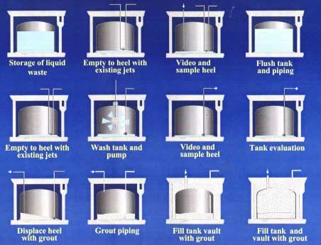
0.000079 to 0.002 in.)] and is larger in diameter than clay [• Step 8: The video and physical samples will be evaluated. The waste will be removed from the
tank walls, tank bottoms, and piping to meet “risk-based” closure standards. After cleaning the
tanks will be visually inspected with a video camera and samples of any residual will be
submitted for laboratory analysis. The sampling will consist of representative samples taken
through out the tank farm. Sample analysis may indicate a need for further flushing and waste
removal.
• Step 9: Using several sequential pours, grout will be used to displace and direct the residual heel
to the transfer pump and it will be removed from the tank. The coil piping will be grouted in
place during this pour.
• Step 10: The piping lines to the tank will be grouted.
• Step 11: The tank vault will be filled with grout.
• Step 12: The entire tank and vault will be grouted.
Figure 3.1 INTEC tank farm overview showing the 1136-m3 (300,000-gal.) tanks and vault types
Figure 3.2 Comparison between INTEC sludge and other fluid densities at INEEL
3.3Figure 3.3 Overview of the tank closure sequence
3.4 Wash Ball and Directional Nozzle Operation
The wash ball and directional nozzle were selected to clean the tank walls and tank bottom.
3.4.1 Wash Ball
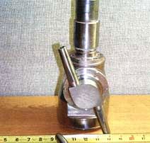
The wash ball, shown in Figure 3.4, is a commercial grade, off-the-shelf tank cleaning system
supplied by Lechler Tank Cleaning Systems.a The wash ball is stainless steel and weighs approximately
71 N (16 lbf). The unit selected to decontaminate tanks WM-182 and -183 contains two opposed 10-mm-
(0.4-in-) diameter nozzles. The wash ball operates using demineralized water supplied from the pump
skid and operates over the pressure range from 0.41 to 0.69 MPa (60 to 100 psi) and flow rates from
0.0038 to 0.0047 m3/s (60 to 75 gpm), respectively. In the tank, the maximum distance of impact from
the wash ball nozzle is estimated to be 10.7 m (35 ft) at 100 psi at a flow rate of 0.0047 m3/s (75 gpm).
The unit is supported by the supply piping from the riser interface adapter mounting flange. The wash
ball rotation is powered by the water flow and the time to complete one wash cycle is 14 min. Wash ball
a
Lechler, Inc., 445-T Kautz Rd., St. Charles, IL 60174 USA, Tel: 800-777-2926, http://www.lechler.com/us/
3.4controls provide rotational movement of the wash ball assembly and remotely controlled on/off ball valve
for supply wash water. The wash water pressure is measured.
The water supply system will deliver demineralized water to both the nozzles and spray rings. The
maximum output capacity of demineralized water is 0.0050 m3/s (80 gpm) at 0.83 MPa (120 psi). The
average planned output capacity is 0.0037 m3/s (60 gpm) for 12 hrs. Measurements will be made of the
total system water usage and the overall instantaneous flow rate. The water supply system does not
include freeze protection. All systems will be drained annually when the temperature is 2 to facilitate disposal. Water volume added that increases pH to >
than pH 2 will potentially be evaporated prior to disposal. So methods that clean the tanks adequately
while limiting water use may reduce the cost of the remediation. Spray techniques that could limit water
use by increasing effectiveness of dissolution and removal of solids from tank surfaces include: use of
heated water, use of chemically treated water, use of higher pressure and lower flow rate.
3.4.2 Directional Nozzle
The full-scale half-tank wash ball tests demonstrated the need for directional nozzles that can be
oriented to wash selected sections of the tank that require additional coverage. These two nozzles will be
placed 180 degrees apart in the outer risers, 0.9 m (3 ft) from the tank wall, and approximately 4.6 m (15
ft) above the bottom of the tank. The 10-mm- (0.4-in.-) diameter nozzles will operate at 0.83 MPa (120
3.5psi) and provide 0.0025 m3/s (40 gpm) per nozzle. Each nozzle will have 350 deg horizontal rotation and
120 deg vertical rotation and be capable of directing water to the bottom and walls of the tanks. The
nozzles will be controlled remotely; the operators will be in a trailer outside of the tank farm. The
directional nozzles will not be operated simultaneously with the wash ball. A camera and light, shown in
Figure 3.5, are located adjacent to each directional nozzle and will follow the nozzle motion. An air lance
will be used to clean the camera lens. The directional nozzle assemblies have rotational and up/down
control and remotely controlled on/off ball valve for supply wash water. The wash water pressure is
measured.
Figure 3.5 Directional nozzle, light, and camera configuration
Figure 3.6 Video camera showing lights and purge air ring
3.4.2.1 Observations
The directional nozzle operation will be utilized for two main purposes: 1) to apply concentrated
streams of water to the tank walls, steam coils, or floor to dislodge accumulations of tenacious solids and
2) to sweep solids to the entrance to the steam jet. Controlling the operation of the directional nozzle in
3.6both of these cases will be done manually with the operator observing nozzle location via the video
camera. A method of automation may assist during remediation by providing some pre-programmed jet
patterns to sweep across the floor of the tank to push solids to the entrance to the steam jet or to focus or
go back and forth across a patch of tank wall. If significant aerosol generation inhibits visualization via
the camera, a visualization system may permit longer periods of operation before mist obscures the vision
of the camera. A virtual visualization system such as the one developed to enhance borehole miner
operation during remediation of the Old Hydrofracture Tanks at Oak Ridge or an infrared system to
permit vision through the mist are potential approaches.
3.4.3 Video Camera
The video camera selected is a commercial grade color unit manufactured by Everest/VITa with
integrated lights and a self-contained control system. The unit weighs about 58 N (13 lbf) and is finished
in polished stainless steel to facilitate decontamination. The lens is a Ca-Zoom model PZT 4.2 with 18:1
optical zoom and 4:1 digital zoom for a total of 72:1 zoom. The camera is waterproof to a depth of 46 m
(150 ft) and the camera head is pressurized at 69 kPa (10 psi). The camera, lights, and control system
operate at 120 VAC at 10 amps that is supplied by a vendor furnished dedicated cable from the control
trailer to the camera. The camera is supported by pipe from the riser interface adapter mounting flange
that has been modified with an additional ring of jets for directing purge air across the lens (Figure 3.6).
The video camera has lights and it is controlled and recorded at the control trailer. Instrument air at 69
kPa (10 psi) and 0.028 to 0.57 m3/s (1 to 2 cfm) supplied from the pump skid is provided to clean the
camera lens. The instrument air pressure is regulated locally and the pressure is verified with a pressure
switch. A liner actuator on the spray ball/video camera mounting flange operates using 120 VAC at 2
amps.
3.4.3.1 Observations
Discussions with the INEEL team revealed that in the past camera components overheated from the
proximity of the camera to the lights. Additional shielding between the lights and the camera were being
implemented. Staff at ORNL noted that they also experienced problems with cameras overheating and
radiation damage. ORNL devised heat shields that were somewhat effective at delaying the heat damage.
They also routinely pulled the overview cameras out of the tank and took them to a glove box where they
were able to replace the video camera modules, lights, and other damaged components and repair the heat
shields.
The location of the camera can also significantly influence camera performance. During periods of
operation when there is a dense aerosolization of water vapor, the view from a camera located near or at
the directional nozzle or spray ball will be particularly hampered by the fog. A much clearer view could
be attained from a video camera located closer to the water impact zone or located so that the impact zone
is viewed from the side rather than in line with the nozzle.
a
Everest VIT, Inc., 199 Highway 206, Flanders, NJ 07836 4500 USA, Tel: 888-332-EVIT (3848), http://www.v-i-
t.com/ptz/cazoom.html
3.73.4.4 Riser Interface Adapter
The riser interface adapter is the mounting point for the spray ball/video camera system support
flange. The adapter connects to the tank central riser using an existing “swing bolt” design configuration.
The adapter includes a spray ring section for decontamination of the adapter when it is removed from the
tank. The spray ring operates using either plant water supply or demineralized water supplied from the
pump skid at 69 to 414 kPa (10 to 60 psi) and flow rates from 0.00012 to 0.00032 m3/s (2 to 5 gpm),
respectively. The spray ring pressure is regulated locally and monitored remotely for signs of nozzle
plugging. The weight of the stainless steel adapter and associated spray ball and video camera systems
are supported by an “A” frame support system between the riser interface adapter and the exposed
concrete bunker top surface located above the tank and not by the tank riser.
3.4.5 Installation and Operation Sequences
The installation sequence includes:
• Position the “A” frame support system on the bunker and remove the cross frame brace.
• Position the interface spool piece over the riser swing bolt flange.
• Align the “A” frame lip of the spray ring assembly, attach the cross frame brace, and transfer
the load to the support system.
• Secure the swing bolt flange interface.
• Lower the upper flange assembly with the spray ball and video camera system onto the riser
adapter flange and secure.
• Connect the camera cable, spray ball supply hose, linear actuator power/control cable, camera
lens window air purge supply hose, and spray ring demineralized water supply hose to the
appropriate bulkhead connectors on the enclosure wall.
The operational sequence includes:
• Turn on the video cameral control consol and video recording equipment in the control
trailer.
• Ensure that the camera lens window air purge supply is on.
• Perform a visual inspection of the tank wall, all cooling coils, tank heel level, and the overall
condition of the tank interior.
• Verify that the camera splash shield is in place.
• Power up the wash pump and perform decontamination operations; record all operations in
the VCR.
• Power up the steam jet and remove the tank heel contents as necessary to achieve optimal
solids removal.
To control contamination during operations procedures are developed based on the following
assumptions:
• The interior of the tank and risers are the primary sources of contamination.
• The area around the vault openings is contaminated.
• During insertion or removal of equipment, the tank entry enclosure will be open to
atmosphere.
3.8Spread of contamination will be reduced by the use of controlled air flow, physical barriers, and a
demineralized wash down system. During any time that the 31-cm- (12-in.-) diameter riser is open, an air
flow of 0.64 m/s (125 ft/min) will be maintained into the tank. This same airflow will be maintained at
the top of the riser vault openings. To meet this demand, the existing vessel off-gas system will be
modified. Equipment removed from a riser will be bagged during withdrawal.
3.5 Retrieval and Transport
Waste suspended by the wash ball and directional nozzles will be pumped from the tank using the
variable depth steam jet and transported through piping to another tank, such as tank WM-189, for
storage.
3.5.1 Variable Depth Steam Jet Pump
The new 5-cm- (2-in.-) diameter variable depth steam jet pump will utilize the existing 3.8-cm- (1.5-
in.-) diameter steam jet steam supply and be installed into the existing 31-cm- (12-in.-) diameter tank
riser. A linear actuator is used to adjust the height of the steam jet assembly over the range from 15 to 25
cm (6 to 10 in.). The steam line is instrumented with a pressure transmitter. Valves for the wash water to
rinse out the ejection pipe and to isolate the waste ejection line are remotely controlled. The following
ejected waste water parameters are to be measured: mass flow rate, density and total flow of ejected
waste water, and gamma radiation of the ejected waste water. A model of the steam jet used during the
retrieval tests is shown in Figure 3.7.
Figure 3.7 Model of steam jet used during retrieval tests
3.5.1.1 Observations
Providing an adjustable height steam jet inlet and increasing the steam jet pumping capacity to match
or surpass the water utilization rate of the wash ball or the directional nozzles are the goals of the new jet
pump installation. Both features should significantly increase the performance of the tank remediation.
3.9The ability to lower the jet pump to just above the floor permits removal of much more slurry and reduces
the heel remaining in the tank. Subsequent washings further reduce the solids loading through additional
dilution and retrieval. The ability to retrieve at a rate equal to or faster than achieved by washing permits
retrieval of the agitated solids prior to the onset of gravitational settling.
3.5.2 Pipeline
Transport of slurry from the tank being washed and remediated to the storage tank makes use of
existing piping. This piping includes bends, elbows, changes in elevation, and passage through valves.
To determine whether solids would accumulate in places such as elbows, dead ends, or contractions or
expansions in the line, a clear plastic model of the pipeline was constructed. The entire length of this line
is shown in Figures 3.8 and 3.9. Tests were conducted to evaluate transport of slurry provided by the
steam jet and the solids concentration that could be successfully transported without plugging any lines.
Figure 3.8 View of the entire above ground piping model
Figure 3.9 Close up of piping model showing valve contractions in black.
3.5.2.1 Observations
Visual observation of slurry transport start up transients, through review of a video of the transport,
were very revealing. These tests showed that air entering the lines prior to operation and air introduced
by a partially submerged inlet remained in the lines for a significant time after initiation of transport.
Pulsating, stratified two-layer (fluid and air) flow persisted through most of the transport. These details
showed that use of a coriolus mass flow meter to quantify the amount and density of the fluid transferred
would not be reliable. These types of flow meters operate accurately when the pipeline is full of fluid.
3.103.6 Evaluation of Equipment Performance during Mockup Tests
Tests of equipment performance with simulants were conducted to ensure that the approach and
equipment selected for waste retrieval perform as anticipated. The spray ball and the auxiliary jet
operation were evaluated during tests conducted in a half-circumference, full-diameter tank. These tests
are described in the report INTEC Tank Farm Facility Closure Mockup Test Report Project File No.
015722 (INEEL 2001). Information from the tests, pertinent to this evaluation is presented here.
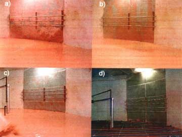
Tests were conducted in a half-circumference, full-diameter tank, shown in Figure 3.10. The
plywood tank included a stainless-steel wall section with stainless steel tubes that simulated cooling coils
attached to the wall. Cooling coils were also located on the floor to simulate the physical coils in the
actual tanks. To model the waste, simulant was applied to the walls of the tank and on the tank floor to an
initial depth of 20 cm (8 in.), covering the cooling coils as shown in Figure 3.10 a. The stimulant was
selected to match physical characteristics such as solids settling rate, density, and viscosity of sludge and
included kaolin clay, iron oxide and aluminum sulfate. Two recipes for surrogate solids were prepared:
one thick recipe [1112 N (250 lbf)] for trowel application to the stainless steel walls and pipes and one
thinner consistency for application to the tank floor to cover the cooling coils. The spray ball and steam
jet were installed in the tank in prototypic locations. In addition operation of a video camera was
evaluated. The test also included using directional nozzles to remove the simulated waste.
Figure 3.10 Test sequence during tests with wash ball in the test tank.
a) initial condition with surrogate waste covering tank wall,
b) initial washing of the tank, c) subsequent washing of the tank,
d) final washing of the tank.
3.11During the tests nozzle bore diameters ranging from 7 to 12 mm (0.28 to 0.47 in.) were tested. Based
on the results of these tests a 10-mm- (0.4-in.-) diameter bore was selected for installation in the wash ball
for cleaning of tank WM-182. To further enhance the performance of these nozzles, the bore was
machined and polished to a constant 10-mm- (0.4-in.-) diameter throughout the entire length.
3.6.1 Evaluation Summary
• Video camera equipment and systems testing demonstrated the effectiveness of the remote
camera operations, camera mounted lights, and an air lance for keeping the lens dry during tank
retrieval procedures.
• Tank washing and mixing of surrogate solids determined the efficiency of the washing system
and the functional performance of the support systems. The wash ball nozzle size was selected
and the need for directional spray nozzles to wash the floor and walls was determined and tested.
• Steam jet testing evaluated the transfer of surrogate solids from the tank and established improved
coordination between washing and mixing systems.
• Slurry pipe flow testing permitted observation of removed pumped solids moving through clear
piping with bends and simulated valves. No blocking in the discharge lines was observed.
3.6.2 Observations
The tests were conducted to provide both qualitative and quantitative results of equipment
performance. Successes included:
• Visualization of the wash ball spray pattern and observation that additional directed jets were
required to move solids from the sides of the tank to the steam jet inlet
• Incorporation and testing of directional nozzles that were able to mobilize and direct sludge from
the tank edges to the steam jet inlet
• Visualization of the erratic two-phase flow during slurry transport through the pipeline model.
Based on these results opportunities exist to:
• Develop an application strategy for deploying the directional nozzles to mobilize and move the
solids to the steam jet
• Develop an application strategy for integration of water injection via either wash ball or
directional nozzle with slurry removal via steam jet operation. This strategy should address when
to operate concurrently, when to operate sequentially, and how to set the flow rates of each device
to determine whether fluid will accumulate, stay constant, or decrease when the equipment is
operating
• Develop criteria, based on measurements of water usage, fluid density, and radiation levels
addressing when to continue water addition for tank washing and solids movement, when to cease
tank washing, and when to cease steam jet retrieval.
3.123.7 Tank Containment
The differential pressure of each enclosure is monitored with respect to the internal tank pressure.
HEPA filter differential pressure is measured to detect air flow and clogging of the filter. Also the
ventilation fan speed is monitored and speed is controlled using a variable frequency drive.
3.8 Closure
To simulate closure activities, a heel displacement test was conducted in a 0.9-m- (3-ft-) high, full-
diameter tank. The tank included simulated steam coils. The purpose of the test was to use grout
placements to move the residual heel to the retrieval pump. Figure 3.11 shows the basin and steam coils,
while Figure 3.12 shows one of the grout pours into the basin to cover the coils.
The grout pour evaluation was quite successful. By adding the grout in series of five pours, each
focusing on separate areas of the tank, a method was developed to channel the remaining slurry to the
entrance to the steam jet to permit additional slurry retrieval. The pattern described used a series of five
pours that formed a star pattern. Consider the five points of a star with the steam jet located at the
intersection between points 3 and 4. Pours one and two occurred on either side of the tank at points 2 and
5. After these pours, a channel exists between point 1 and the steam jet inlet. Pour three occurred at point
1, forcing fluid through the channel to the steam jet inlet. Pours four and five occurred at points 3 and 4,
completing transfer of fluid from the tank floor to the steam jet. The final pour submerges the inlet of the
steam jet. These grout pours are accomplished using either one or both of the tanks two risers.
Figure 3.11 Tank basin showing location of cooling coils
3.13Figure 3.12 Pouring grout over the tank bottom to direct fluid to the steam jet entrance
3.8.1 Observations
The method of sequentially pouring grout onto the tank floor and cooling coils has shown the
usefulness of this method for permitting retrieval of additional slurry from the tank using the installed,
variable depth steam jet.
3.144.0 PNNL and ORNL Technology Exchanges with INEEL
Through the US DOE Tanks Focus Area and through collaboration with Hanford via US DOE EM-30
and EM-40 funding, staff at PNNL and Hanford are developing and deploying technologies for waste
retrieval from tanks, waste treatment, and tank closure. Many of the systems developed and tested by
PNNL have been deployed successfully at ORNL, Savannah River Site (SRS), and West Valley Nuclear
Services Corporation. These systems have been designed for operation retrieving waste types that differ
from the light, billowy solids observed at INEEL in the WM tanks. This broader technology base may be
useful for consideration by staff at INEEL if problems develop during remediation that cannot be solved
using existing equipment by changes in operating procedures and different technologies must be
considered.
To start this dialog, program staff Keith Quigley and Steve Butterworth from INEEL visited ORNL
and PNNL in April, 2001 to meet with technology developers.
4.1 INEEL Meeting at ORNL
The briefing at ORNL included presentations and discussions of retrieval and closure activities for the
Gunite and Associated Tanks, Old Hydrofracture Facility Tanks, and Federal Facility Agreement Tanks.
Retrieval activities were discussed for the Bethel Valley Evaporator Service Tanks and Melton Valley
Storage Tanks. The ORNL site visit included tours of several tank farm facilities and the Tanks
Technology Cold Test Facility.
4.2 INEEL Meeting at PNNL
The agenda for the INEEL meeting at PNNL and a synopsis of the interactions follows.
4.2.1 Agenda
Wednesday April 25, 2001
Hanford Training Facility Multnomah Falls Room
7:15 Meet at Hanford Training Facility Multnomah Falls Room
7:30 – 9:30 Cold Test, Training And Mockup Facility Priority Lessons Learned Workshop,
Greg McLellan
Welcome/Purpose, Introductions, and Success Criteria
Key Drivers, Project Overview and Status
Conduct Cold Facility Lessons Learned, Identify what has “Worked Well”, Determine
impact items and why
2400 Stevens Saddle Room,
9:50 End Effector Development - Brian Hatchell
10:10 West Valley Spray Ball – Dave Jackson
10:30 Jet Cleaning – Borehole Miner - Judith Bamberger
4.1You can also read