PREMIUM PORTABLE MIXER-RECORDER

          USER GUIDE
←
→
Page content transcription
If your browser does not render page correctly, please read the page content below
PREMIUM PORTABLE MIXER-RECORDER
USER GUIDE
Legal Notices                                                           Manual Conventions
Product specifications and features are subject to change without
prior notification.                                                     SYMBOL     DESCRIPTION

                                                                                   This symbol is used to show the order in which you select menu
Copyright© 2020 Sound Devices, LLC. All rights reserved.                           commands and sub-options, such as: Main Menu > Outputs
                                                                            >
This product is subject to the terms and conditions of a                           indicates you press the Menu button for the Main Menu, then
software license agreement provided with the product, and                          scroll to and select Outputs by pushing the Knob.
may be used in accordance with the license agreement.                       []     This symbol is used to convey selectable menu items.
This document is protected under copyright law. An authorized
licensee of this product may reproduce this publication for the             *      This symbol is used to convey factory default settings.
licensee’s own personal use. This document may not be reproduced                   A plus sign is used to show button or keystroke combinations. For
or distributed, in whole or in part, for commercial purposes, such                 instance, Ctrl+V means to hold the Control key down and press
as selling copies or providing educational services or support.                    the V key simultaneously. This also applies to other controls,
This document is supplied as a technical guide. Special care                +      such as switches and knobs. For instance, MIC+HP turn means
                                                                                   to slide and hold the MIC/TONE switch left while turning the
has been taken in preparing the information for publication;
                                                                                   Headphone (HP) knob. METERS+SELECT means to hold the
however, since product specifications are subject to change,                       METERS button down as you press the SELECT knob.
this document might contain omissions and technical or
typographical inaccuracies. Sound Devices, LLC does not accept                     A note provides recommendations and important related
responsibility for any losses due to the user of this guide.               Note    information. The text for notes appears italicized.

Trademarks                                                                         A cautionary warning about a specific action that could cause
The “wave” logo is a registered trademarks; SuperSlot, and                         harm to you, the device, or cause you to lose data. Follow the
Wave Agent are trademarks of Sound Devices, LLC. Dante is a                 *      guidelines in this document or on the unit itself when handling
registered trademark of Audinate. Windows and Microsoft Excel                      electrical equipment. The text for cautionary notes also appears
                                                                                   italicized and bold in a different color.
are registered trademarks of Microsoft Corporation in the U.S.
and other countries. Bluetooth LE is a registered trademark
of Bluetooth SIG, Inc. Android is a registered trademark of
Google. iPad is a registered trademark of Apple Inc. All other
trademarks herein are the property of their respective owners.

WEEE Statement
If you wish to discard a Sound Devices product in Europe,
contact Sound Devices (Germany) for further information.

Warning! This device can drive headphones to potentially
dangerous levels. Do not listen at high volume levels for
long periods.

Read and fully understand this manual before operation.
 Included Accessories
  DESCRIPTION

  Cordset 6’ AC cable
  XL-WPTA4 power supply TA4 Connector
  Scorpio LCD cover
  Antenna, SMA connector
  Promo Sticker (white)
  Promo sticker (black)
  Dot: Red, Yellow, Blue,Green, Purple, White
  (8 each)

Post Office Box 576                       +1 608.524.0625 main
E7556 State Rd. 23 and 33                 +1 608.524.0655 fax
Reedsburg, Wisconsin 53959 USA               800.505.0625 toll free
www.sounddevices.com                         support@sounddevices.com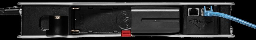
Scorpio User Guide 1/21
This document is distributed by Sound Devices, LLC in online electronic
(PDF) format only. Published in the USA.
This table provides the revision history and cross-reference
links to “what’s new” in this guide.

              DATE               DESCRIPTION

              05/19              v1.0 Initial release
              7/19               v1.20 SL-6 Operation, Sticky Notes,
                                 Take List, File Copy.
              8/19               v1.21 Stability Improvements
              8/19               v2.00 Dugan Automix, Additional USB
                                 MIDI Controller supprt, Nested Folder
                                 Support, SL-6 Support for Sennheiser
                                 6042.
              10/19              v3.00 MixAssit, CL-12 Support,
                                 Timecode stamped AAC file recording,
                                 Smart Battery telemetry, Horizontal
                                 Meter Options.
              12/19              v3.10 Support for the XL-AES
                                 accessory, new graphical EQ, USB
                                 audio input/output, new headphone
                                 encoder menu.
              2/20               v3.20 Bluetooth LE support for SD-
                                 Remote, new bluetooth menu option.
              2/20               v3.21 SD-Remote support for iPad
              4/20               v4.00 Support for CL-16, output
                                 naming, bus soloing, custom SD card
                                 names.
              5/20               V5.00 Support for NoiseAssist and the
                                 Sonosax SX-LC8+ Controller.
              7/20               v6.00 Support for the SL-2, new Audio
                                 Ltd A10 SuperSlot screens.
              8/20               v6.10 Support for P.I. Engineering’s
                                 X-keys® Programmable Keypads,
                                 Sticks & Keyboards.
              9/20               v7.00 Support for the WIsycom
                                 MCR54, Compressors, Q-marks, Soft
                                 pickup for faders, enhanced control
                                 via SD-Remote.
              10/20              v7.10 New record folder prompts when
                                 recording after midnight, link quality
                                 indicator for Wisycom MCR54.
              12/20              v7.20 SD-Remote for iPhone support.
                                 Support for optional four- and eight-
                                 instances of NoiseAssist Plugin.
                                 NoiseAssist instances can now be
                                 applied to any bus.
              1/21               v7.30 Sony DWR-S03D SuperSlot
                                 support. SD-Remote for Android
                                 phones support.
              1/21               v7.40 CEDAR sdnx Plugin. Record
                                 Folder and Take Renaming.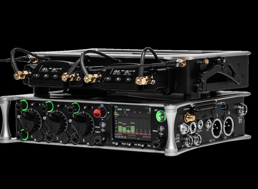
Welcome to Scorpio
THE NEW ERA OF PRODUCTION SOUND.

Dear Sound Professionals,

Thank you very much for your interest and purchase of the Scorpio. We at Sound Devices are extremely proud of this product. We consider the
Scorpio our best yet, from every aspect.

We also want to thank you for your direct contribution to this product’s success. Countless conversations were shared with industry professionals
regarding workflows, frustrations, wants, and needs. The knowledge obtained from these conversations drove the design and engineering of the
Scorpio.

Please stay in touch. We will always be here to help, listen to feature requests, and hear about your adventures with the Scorpio.

We are honored to be part of your kit.

Sincerely,
Sound Devices

Scorpio User Guide                                                                                                                                  IV
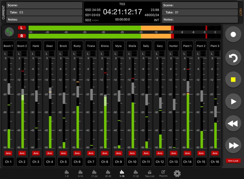
Table of Contents
PANEL VIEWS..... ....................................... 1        TABLET....................................................55
FRONT PANEL..... ....................................... 1        PHONE....................................................55
LEFT SIDE PANEL.......................................3           CHANNEL SCREEN ....................................57
RIGHT SIDE PANEL.....................................4            TAKE LIS T................................................58
REAR PANEL..............................................5         QUICK SETUP................................. ..........61
TOP PANEL................................................5        DANTE.....................................................62
HOME SCREEN ...........................................6          USB- A ........................................... ..........62
CHANNEL SCREEN ......................................7            USB-C.....................................................62
CHANNEL INPUT SOURCE............................8                 SPECIFICATIONS ............................ ..........63
CHANNEL BUS SENDS.................................8               GLOSSARY...............................................67
VIR TUAL KEYBOARD...................................9
PHRASE MANAGER................................... 10
CHANNEL EQ............................................ 11
CHANNEL COMPRESSION .......................... 11
MENUS.................................................... 1 2
POWER.................................................... 1 3
CHANNEL SETUP....................................... 1 4
CHANNELS 1 3-32.................................. .... 1 4
BUSES..................................................... 1 5
OUTPUT S.................................................. 16
LIMITERS................................................. 1 8
AUTOMIXER.............................................. 19
NOISE SUPPRESSION ................................21
INS TALLING PLUGINS................................23
METERS...................................................24
TIMECODE.......... ......................................25
RECORD/PLAY..........................................26
Q-MARKS.................................................27
FILES......................................................28
SLATE/COMS/RETURNS.............................32
SUPERSLOT..............................................33
SL -2........................................................33
SL -6........................................................36
SYS TEM...................................................43
CONTROLLERS..........................................4 4
GPIO CONFIGURATION MENU DETAILS........45
SUPP OR TED THIRD-PAR T Y CONTROLLERS...46
MENU + PFL SWITCH ACTION .....................49
FRONT PANEL SHOR TCUT S.........................50
USB KEYBOARD........................................51
SD-REMOTE..............................................52

Scorpio User Guide                                                                                                                  V
Panel Views
   FRONT PANEL
Channel Trim                      Channel Fader                               Meter Button                       LCD Display
               Channel Ring LED                   PFL Switch                                 Transport Control                 Power Switch/LED Indicator

                                                                                                                                                            Menu Button

                                                                                                                                                            Headphone
                                                                                                                                                            Knob

                                                                              Select Knob     Mic/Tone Switch    */** Switch       Rtn/Fav Switch

   CHANNEL TRIM Turns the channel on/off and sets the input sensi-            Function          Action
   tivity for the channel. To conserve power, turn off unused channels by
   rotating channel trim fully counterclockwise. Channel 13-32 trims are      Record            Push up the Transport control to begin recording a new file.
   accessible via the Channels 13-32 menu or using */** + PFL switch                            The LED ring illuminates red while recording is underway.
   shortcuts. Use Toggle Switch Actions to set the Select and /or HP          Stop              Press in the Transport control to stop recording or playback.
   knobs as trims for Ch 13,14.                                                                 While in standby, press and hold to display next take name.

   CHANNEL LED RING Provides visual indication of channel signal              Play              Push down on the Transport control to begin playback of the
   condition, solo and mute, and whether a channel is on or off.                                last file recorded or file currently loaded. While in playback,
                                                                                                push down again to pause playback. The LED ring as well as
   CHANNEL FADER Controls the audio level of the channel as it                                  the active file in the display will flash to indicate that Pause
   contributes to the L/R mix and any destinations selected in routing                          is active. Push down again to continue playback.
   as “Post”. Channel 13-32 faders are accessible via the Channels            Rewind / Load     While in standby, push left to load the previous take. While
   13-32 menu or using */** + PFL switch shortcuts. Use Toggle Switch         Previous Take     in playback, push and hold left to rewind.
   Actions to set the Select and /or HP knobs as faders for Ch 13,14.                           When the Scorpio is playing back or paused, moving the
                                                                                                joystick to the left () fast forwards at 2x speed, then after
   for Ch 13,14.                                                                                holding for 5 seconds, it increases to 16x speed.. Push right
                                                                                                while holding Select to add a Q-mark.
   TRANSPORT CONTROLS A joystick (with its illuminated LED ring)
   on the front panel is used to perform various transport control func-      Scrub             While playing or paused, press the headphone knob >0.5 s
   tions. (see table below). The ring LED will flash orange indicating post                     to enter Scrub mode. Then rotate clockwise for fast forward
   roll while writing to media.                                                                 or counter-clockwise for rewind speeds of 0x, 1/8x, 1/4x,
                                                                                                1/2x, 1x, 2x, 4x, 8x, and 16x. The audio may be heard in
                                                                                                scrub mode up to 2x speed.

 Scorpio User Guide                                                                                                                                                       1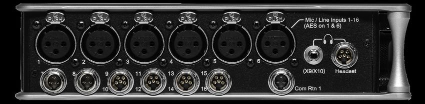
METER BUTTON Push to view and select various metering presets.
Used with Select Knob. Press again to return to Home Screen. Push
with channel Select switched 1-12 for shortcut to Meters Preset 1-12.
Push and rotate HP knob to zoom meter scale. Push and Push HP
knob to access Receiver Overview screen if a SuperSlot accessory is
connected.
SELECT KNOB
1. Push to view Outputs list, rotate and push to Select Output Screen.
Push Meter Button to return to Home Screen.
2. Rotate to select track in display, push both Meter and Select at
the same time to arm/disarm track. While holding the Meter Button,
multiple consecutive tracks may be armed by holding in the Select
Knob and rotating.
3. Use with Meter Button to scroll through meter views then push to
Select.
4. Push with Channel Select switches 1-12 for shortcut to Bus 1-10,
L,R routing.
5. Menu navigation and push to Select.
6. Hold then press >>,
LEFT SIDE PANEL

                                                       Mic/Line Inputs 1-6 female XLR jacks                            Headphone/(X9/X10)
                                                       AES3/AES42 on XLR Inputs 1 and 6                                3.5mm jack

                                 Mic/Line Inputs 7-8              Mic/Line Inputs 9-16            Com Rtn 1 TA3 jack      Headphone/
                                 TA3 jacks                        TA5 jacks                                               Headset/External Slate
                                                                                                                          Mic TA5 jack

INPUTS 1-6 FEMALE XLR JACKS Active-balanced analog micro-                                     COM RTN 1 TA3 JACK Balanced connection for Com Return 1 audio
phone or line-level inputs. Inputs 1 and 6 can also accept AES3 or                            input. [pin-1 = Ground, pin-2 = hot (+), pin-3 = cold (-)]
AES42 signal. [pin-1 = ground, pin-2 = hot (+), and pin-3 = cold (-)]
                                                                                              HEADPHONE/(X9/X10) 3.5 MM JACK Unbalanced output and
110 ohm cables should be used for AES3 or AES42 inputs.
                                                                                              TRS headphone output. Warning! This output can drive headphones
MIC/LINE INPUTS 7-8 TA3 JACKS Active-balanced analog                                          to potentially dangerous levels. Routing determined in the Outputs
microphone or line-level inputs. [pin-1 = ground, pin-2 = hot (+), pin 3                      menu. [Sleeve = ground, tip = left (X9), ring = right (X10)]
= cold (-)]
                                                                                              HEADPHONE/HEADSET TA5 JACK Headphone and slate micro-
MIC/LINE INPUTS 9-16 TA5 JACKS Active-balanced analog mi-                                     phone connections [pin-1 = HP right, pin-2 = HP left, pin-3 = ground,
crophone or line-level inputs. [pin-1 = ground, pin-2 = Ch.1 +, pin-3 =                       pin-4 = Mic -, pin-5 = Mic+]
Ch.1 -, pin-4 = Ch.2 +, pin-5 = Ch. 2 -]
                                                                                              Route HP-L and HP-R to X9/X10 to control headphone level with the
                                                                                              headphone knob and to send headphone signal to the TA5 output.

Scorpio User Guide                                                                                                                                                    3
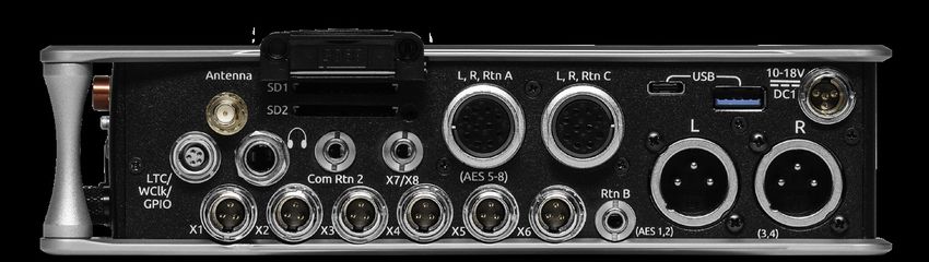
RIGHT SIDE PANEL

                            Antenna SMA                    SD Card slots 1 & 2                     L,R,Rtn C 10 pin jack         USB A port
                            connector
                                           1/4” headphone jack                     L,R,Rtn A (AES 5-8)              USB C Port          10-18 V DC1 TA4 jack
                                                                                   10 Pin jack

                           LTC/Wordclock/5-pin X1-X6            Com Rtn 2        X7/X8                   Rtn B             Main Outputs L (AES 1,2),
                           LEMO jack           TA3 jacks        3.5 mm jack      3.5 mm jack             3.5 mm jack       R (AES 3,4) Male XLR jacks

ANTENNA RP-SMA-MALE CONNECTOR Connects to included                                              ¼” HEADPHONE JACK 1/4-inch TRS headphone output. This
external antenna for Bluetooth LE.                                                              output is always fed by the headphone source levels. Warning! This
                                                                                                output can drive headphones to potentially dangerous levels. [Sleeve
SD 1 AND 2 CARD SLOTS Insert SD card media for recording.
                                                                                                = ground, tip = left, ring = right]
Insert label side down.
                                                                                                COM RTN 2 3.5 MM JACK Balanced, 1-channel 3.5 mm female
L,R,RTN A (AES 5-8) AND C 10-PIN JACKS Each connection
                                                                                                connector for Return 2 audio input. [Sleeve = ground, tip = hot, ring
includes a pair of outputs and a stereo unbalanced return input.
                                                                                                =cold ]
Analog Output levels are selected between Line, -10, and Mic levels in
Main menu > OUTPUTS section. 10-pin A outputs can be set to send                                X7/X8 3.5 MM JACK Unbalanced stereo 3.5 mm female connector.
AES3 digital signals (AES 5-8). Output may be sourced from L,R or any                           Routing determined in the Outputs menu. [Sleeve = ground, tip = X7,
of the 10 mix buses in Main menu > OUTPUTS.                                                     ring = X8]
USB C PORT                                                                                      X1-X6 TA3 JACKS Line, -10, or Mic level selected in Main menu
1. File transfer.                                                                               OUTPUTS section. Routing determined in the Outputs menu. [pin-1
2. 2-in/2-out USB audio streaming.                                                              = Ground, pin-2 = hot (+), pin-3 = cold (-). Float pin-3 to un-balance]
USB A PORT                                                                                      RTN B 3.5 MM JACK Unbalanced stereo 3.5 mm female connector
1. USB keyboard.                                                                                for Return B audio input. [Sleeve = ground, tip = left, ring = right]
2. USB to SD-Remote Android app.
                                                                                                MAIN OUTPUTS L (AES 1,2), R (AES 3,4) XLR JACKS Analog
3. USB to the CL-16, CL-12, and other approved 3rd party fader
                                                                                                outputs on standard 3-pin XLR-3M connectors. Analog Output levels
controllers.
                                                                                                are selected between Line, -10, and Mic levels in Main menu >
4. Supports USB hubs.
                                                                                                OUTPUTS. Can be set to send AES3 digital signals (1,2 and 3,4 on L
10-18V DC1 TA4 JACK Accepts DC voltages from 10–18 V for                                        and R respectively) in Main menu > OUTPUTS. Routing determined in
powering. [pin-1- GND, pin-2- Smart Battery DATA, pin-3- Smart                                  the Outputs menu. [pin-1 = Ground; pin-2 = hot (+); pin-3 = cold (-).
Battery CLOCK, pin-4- +10-18 VDC]                                                               Unbalance by floating pin-3]
LTC/WORDCLOCK/5-PIN LEMO JACK Timecode I/O, Wordclock.
[pin-1- GND, pin-2- LTC or WORDCLOCK IN, pin-5- LTC or WORDCLOCK
OUT (Pins 2 and 5 are software selectable)].

Scorpio User Guide                                                                                                                                                        4
REAR PANEL                                                                                                      Dante /Ethernet RJ-45 jacks

                                                                                                          Primary Ethernet port   Secondary Ethernet port
                        10-18 V DC 2 TA4 jack             Battery 1, Battery 2 Docking

10-18V DC2 TA4 JACK Accepts DC voltages from 10–18 V for pow-                    DANTE RJ45 JACKS Two-1 GbE ports serving as a Dante audio
ering. [pin-1- GND, pin-2- Smart Battery DATA, pin-3- Smart Battery              network connections. The Dante interface provides 32 inputs and 32
CLOCK, pin-4- +10-18 VDC]                                                        outputs simultaneously with sampling rates up to 96 kHz. Routing
                                                                                 is defined through the Channel Source and Output menus. Dante
BATTERY 1, BATTERY 2 DOCKING Sony L-Mount type batteries
                                                                                 Controller app on Mac/PC (from Audinate) needed to route and use
may be used. When connected to an external DC source via DC1 or
                                                                                 Dante.
DC2 the L-Mount batteries can be charged if enabled in the Power
menu.

TOP PANEL
                                                                        SL-6 Port

                                                                    Expansion port

EXPANSION PORT Used for connecting XL-AES 8 Channel AES3
Input Expander and SL-2 Dual SuperSlot Wireless Module.
 SL-6 PORT Multipin Molex Ribbon connector used for connecting SL-
 6. Remove all power on Scorpio and the SL-6 before connecting.
 The SL-Riser is required to connect the SL-6 to Scorpio.
Scorpio User Guide                                                                                                                                          5
HOME SCREEN Smart Battery telemetry Power icon
Media space Q-mark
remaining indicators
Current take name
Individual channel
meters
LR mix bus meters
File elapsed time Selected
headphone preset
Timecode Current sample rate
Current frame rate Metering for
Returns A, B, C
CURRENT TAKE NAME Shows the filename of the currently- SAMPLE RATE / FRAME RATE/ TEMPORARY LEVEL DISPLAY
selected take. 1. Indicates current sample rate.
2. Indicates current frame rate.
SSD, SD1, SD2 Indicates the amount of recording time available
3. Temporarily indicates fader level of last moved fader (red text box).
based on current track count, sample rate, and media routing The
4. Temporarily indicates trim level of last moved trim (green text box).
internal SSD drive has a capacity of 256 GB.
5. Temporarily indicates bus level of last adjusted bus fader (light blue
POWER ICON Indicates approximate voltage condition and current text box).
power source being used 6. Temporarily indicates output level of last adjusted out gain (white
text box).
LR MIX BUS METERS WITH ARM/DISARM INDICATION
7. Temporarily indicates EQ freq and gain of last adjusted EQ (blue
Indicates the peak and VU audio levels of the L/R mix. The L and R
text box when EQ is On, orange text box when EQ is off or band is
indicators turn red to indicate that the tracks are armed for record.
bypassed).
INDIVIDUAL CHANNEL METERS WITH ARM INDICATION
SMART BATTERY TELEMETRY Indicates time remaining and
Indicates the peak and VU audio levels of the individual channel. May
percent remaining of Smart Battery life. Other power sources will
be Pre- or Post- fade depending on Channel to ISO routing.
show voltage.
FILE ELAPSED/ REMAINING TIME Indicates in
SELECTED HEADPHONE PRESET Indicates the currently-selected
Hours:Minutes:Seconds:1/10ths the elapsed time of the current file.
headphone preset.
During playback, displays the elapsed and remaining time in hours,
minutes and seconds. METERING FOR RETURNS A, B AND C Indicates audio level for
the returns.
TIMECODE Indicates current SMPTE timecode value.
Q-MARK Indicates Q-mark number.
Scorpio User Guide 6CHANNEL SCREEN
Channel designation
and user-defined name
Channel Meter view
Channel Trim value Channel Fader Value
Channel Input selection Channel to ISO routing
Channel Linking Channel EQ
Automix
HPF (High Pass Filter) Noise Suppression
Polarity
Channel delay Channel to Bus routing
Limiter
Compressor HP Preset
Slate Mic
Channel Mute L C R pan select Channel Arm
CHANNEL DESIGNATION AND USER-DEFINED NAME Indicates NOISE SUPPRESSION (NA OR NX) Indicates whether the channel
the mixer channel designation and the user-defined name. Both are is selected for Sound Devices NoiseAssist (NA) or CEDAR sdnx (NX)
overlaid onto the channel audio meter. When in a Channel Screen, and how much is applied. Field is grayed out when the
hold the PFL Switch for about 0.5 s to enter the virtual keyboard and Noise Suppression is disabled. White ‘--’ (dashes) when Noise Sup-
enter a user-defined name for the channel. pression is enabled but channel not selected; white ‘dB’ value when
channel is selected. NoiseAssist and CEDAR sdnx are optional paid
CHANNEL METER VIEW Indicates the audio level of the channel.
Plugins.
Metering follows ISO Routing selection, Pre- or Post-fade.
HPF (HIGH PASS FILTER) Indicates on/off status where green
CHANNEL TRIM VALUE Indicates the gain of the channel trim con-
icon and white value = ”On” and gray icon and value = “Off”. The HPF
trol. The gain range depends on the type of input selected.
frequency is variable in 10 Hz steps from 10 Hz to 320 Hz.
Mic: -inf, +12 to +76 dB
Line: -inf, -14 to +50 dB POLARITY REVERSE Indicates polarity status. Green icon = polarity
Dante: -inf, -20 to +50 dB reversed, white icon = polarity normal.
SL-2 (Rx): -inf, -20 to +50 dB
CHANNEL INPUT DELAY Indicates input delay time. The input delay
SL-2 (AES): -inf, -20 to +50 dB
is continuously-variable in milliseconds from 0-50 ms.
SL-6: -inf, -20 to +50 dB
AES3: -inf, -20 to +50 dB CHANNEL TO BUS ROUTING Determines to which bus or buses the
AES42: -inf, 0 to +70 dB channel audio will be sent. When a channel is routed to a bus as a
XL-AES: -inf, -20 to +50 dB Send (bus box highlighted blue), the Send Gain value is used. When
Returns: -inf, -20 to +30 dB a channel is sent Pre (green) or Post (orange), the Send Gain value is
ignored.
CHANNEL FADER VALUE Indicates the level of the channel fader
control, continuously-variable from -inf to +16dB. CHANNEL LIMITER Indicates on/off status of channel limiter.
CHANNEL INPUT SELECTION Indicates which physical audio input CHANNEL COMPRESSOR Indicates the Compressor position in the
is feeding the channel. audio chain. Pre(fade) or Post(fade). Select to enter Channel Com-
pressor screen.
ISO (CHANNEL->ISO) ROUTING Indicates where the isolated
track’s audio is tapped from in the audio chain. Pre-fade or Post-fade. MUTE Indicates mute status of channel. Blue icon = muted. Toggle
mute on/off with the “Tone” switch.
CHANNEL LINKING Indicates the current linking status. The linking
options are Unlinked, adjacent channels (eg. 1,2) and adjacent chan- L C R SELECT Indicates the stereo pan position of the channel’s
nels Mid Side (eg. 1-2MS). Linked parameters are: trims, faders, HPF, contribution to the L/R mix. Orange = selected. Use the */** switch
delay, limiter, mute, ISO, Bus Send 1 and Bus Send 2. Stereo panning to select. Hold */** switch and rotate select knob for continuous
is 1 to L and 2 to R. Adjust the MS balance (width) in the ‘M’ chan- panning positioning. Alternatively, press and hold Select knob, then
nel’s MS balance field by holding */** and rotating Select. use */** switch to pan continuously. Rotating the select knob while
holding */** will change the balance of Mid, Center and Side when
CHANNEL EQ Indicates the EQ position in the audio chain. Pre(fade)
two channels are MS linked.
or Post(fade). Select to enter Channel EQ screen.
ARM Toggle the Rtn/Fav switch.
AUTOMIX Indicates whether the channel is selected for automixing.
Purple text = On and white text = Off. HP PRESET Pressing in HP knob will toggle between HP preset
and PFL. Can be used to listen to channel panning while viewing the
Channel Screen by setting the HP Preset to LR Stereo.
Scorpio User Guide 7CHANNEL INPUT SOURCE CHANNEL BUS SENDS Scorpio User Guide 8
Virtual Keyboard
 Action         Function
 Rotate HP      Scrolls orange highlight through the keyboard
                characters.
 Press HP       Inserts the highlighted character in text field.
 ‘abc’ switch   Quick flick toggles between A-Z and a-z in keyboard.
 Hold ‘abc’     Momentary selection of other case.
 switch
 Delete         Deletes character to the left of flashing cursor.
 Hold Delete    Repeatedly deletes characters to the left of flashing
                cursor.
 Space          Inserts space at the flashing cursor position.
 Hold Space     Repeatedly inserts spaces.
 Save switch    Saves text and exits screen.
 Rotate         Moves the cursor to the left or right in the text field.
 Select
 Quick Press    Switches to the Shifted functions: Clear, End, Home,
 Select         Exit. When shifted functions are active, their text
                changes to white and the non-shifted functions
                change to gray.
 Clear          Clears text from the text edit field.
 End/Home       Moves cursor to end/start of text.
 Exit           Exits screen without saving text edits.

Scorpio User Guide                                                         9
Phrase Manager Phrases entered in the Phrase Manager are available in all virtual keyboard text editing screens such as scene names, channel names, notes, etc. CLEAR Clears all phrases. DELETE Deletes selected phrases. NEW Create new phrase. EDIT Edit selected phrase. INSERT Inserts selected phrase into text. REPLACE Replaces text with current selected phrase. Scorpio User Guide 10
Channel EQ
                                                                                      Low Cut filter value
 MIC Selects EQ state and insert location. Indicates where the EQ is
 inserted into the audio chain. Pre-fade or Post-fade [Off*, Pre, Post].
 EQ will apply to bus sends only when applied Pre-fade.
 TONE Selects EQ band mode [Bypass*, Active]
 */** Selects EQ band. Use Select encoder to adjust frequency and
 HP encoder to adjust gain of the filter. [LF*, MF, HF] All filters are
 sweepable from 20 Hz to 20 kHz.
 RTN Selects Q (bandwidth) of selected band [0.5 - 10] (use Sel or HP
 encoder to adjust).
 FAV Toggles filter type of LF and HF band [Peak, Shelf*].

 The Low Cut value is represented by the leftmost value on the graph
 and is adjustable in the channel screen.

 Channel Compression                                                                                                 frequency and
                                                                                                                     gain indication

 MIC Selects Compression state and insert location. Indicates where
 the compression is inserted into the audio chain. Pre-fade or Post-
 fade [Off*, Pre, Post].
 Compression will apply to bus sends only when applied Pre-fade.
 TONE Selects threshold [0 to -40 dB]
 * Selects Ratio. [1.0:1 to 20:1 in 0.1 steps]
 ** Selects Knee. [Hard, Soft]
 RTN Selects Attack time [1 to 200 ms in 1 ms steps]
 FAV Selects Release time [50 to 200 ms in 1 ms steps, 200 to 1000
 ms in 10 ms steps]

 Note: Compression can also be applied to Buses.

                                                                           Insert location    Threshold      Ratio       Knee          Threshold   Release

Scorpio User Guide                                                                                                                                           11
Menus MAIN MENU Scorpio User Guide 12
Power
Allows configuration of various power settings.

POWER SOURCE ICONS (Batt1, Batt2, DC1, DC2, TC Batt,) Indi-
cates the power condition of each power source. [Green = normal,
yellow = below normal, red = warning]
1. DC1 REF Allows proper power level indicator calibration based
upon the type of DC power source used. [12V DC*, 14 V Li-Ion, 12 V
Lead Acid, Full Range (10-18 V), Smart Battery], NP1 Data.
2. DC2 REF Allows proper power level indicator calibration based
upon the type of DC power source used. [12V DC*, 14 V Li-Ion, 12 V
Lead Acid, Full Range (10-18 V), Smart Battery], NP1 Data.
3. DC LOSS Selects how the unit should operate when DC power is
lost. [Switch to Next Supply*, Turn Off]
4. SMART BATTERY DATA Displays Time Remaining, Percent Re-
maining, Cycle Count, and Temperature of Smart Battery 1 and Smart
Battery 2.
Note: This menu is only displayed when a Smart Battery is connected
4. BATT CHARGING Selects battery charging mode when connected
to an external DC source. [Disabled, When Power On, When Power Off,
Always] Battery charging not available when the SL-6 is connected.
5. USB-A CHARGE PORT Allows charging of compatible external
USB devices such as Android tablets. Set to 500 mA or 1.5 A

Scorpio User Guide                                                    13
Channel Setup
1. PHANTOM VOLTAGE Selects phantom power voltage for all
inputs. [12 V, 48 V*]
2. PFL MODE Selects the source of the PFL feed. [Auto* Pre-fade,
Post-fade] Auto = pre-fade if channel is routed to ISO track pre-fade,
post-fade if channel is routed to the ISO track post-fade.
3. CHANNEL GROUPING Channel Groups can be set to Off, Trim/
Fader, or Fader. Trim/Fader groups allow the smallest channel num-
ber in the group to control trim, fader, record arming, limiters, and
mutes of all channels in the group. Fader groups act just like Trim/
Fader groups but trims remain independent per channel. Groups
that are Off retain their channel routings but settings and levels are
independent per channel. This allows for quick enabling or disabling
of a group without losing group routings.
Trims can only be grouped when all channels of the group share the
same gain range. Gain ranges depend on input type routed to a chan-
nel. See Channel Screen>Channel Trim Value for more detail.
Four channel groups are possible; channels grouped can only be
assigned to one group.
a. Group 1 [1-16]
b. Group 2 [1-16]
c. Group 3 [1-16]
d. Group 4 [1-16]

4. PFL GAIN A preset amount of gain that is applied to any chan-
nel(s) with active PFL.

Channels 13-32
Provides access to channel screens 13-32.
Access is also possible by using the */** + PFL switch shortcuts:
* + PFL 1-12 = Ch 13-24
** + PFL 1-8 = Ch 25-32

Trims, Faders and PFL’s for channel’s 13 and 14 can be controlled by
a combination of the toggle switches beneath the LCD and the Select
and HP Knobs. Setup in the System>Toggle Switch Action menu.
See the Toggle Switch Action section for information on which of the
following optons are available for each toggle switch:

CH 13 OR 14 TRIM/PFL (LATCH) Flick toggle then rotate Select
to adjust ch 13 or 14 trim. Gain values are displayed in the Home
Screen sample rate field. Press Select to PFL. Flick toggle to cancel
mode.
CH 13 OR 14 FADER /PFL (LATCH) Flick toggle then rotate Select
to adjust ch 13 or 14 fader. Gain values are displayed in the Home
Screen sample rate field. Flick toggle to cancel mode
CH 13 TRIM/PFL (MOMENT) Hold toggle then rotate Select to ad-
just ch 13 trim. Gain values are displayed in the Home Screen sample
rate field. Press Select to PFL
CH 14 TRIM/PFL (MOMENT) Hold toggle then rotate HP to adjust
ch 14 trim. Gain values are displayed in the Home Screen sample rate
field. Press HP to PFL
CH 13 FADER/PFL (MOMENT) Hold toggle then rotate Select to
adjust ch 13 fader. Gain values are displayed in the Home Screen
sample rate field. Press Select to PFL
CH 14 FADER/PFL (MOMENT) Hold toggle then rotate HP to adjust
ch 14 fader. Gain values are displayed in the Home Screen sample
rate field. Press HP to PFL

Scorpio User Guide                                                       14
Buses elects routing for Buses L,R and 1-10. S Access buses via Menu > Buses or by holding Select and toggling a PFL switch. When a bus screen is entered, that bus is solo’d by default in both HP L and HP R. If the bus is linked, the odd bus will be heard in HP L and the even bus in HP R. Toggle between Solo and the current HP preset by pressing the HP encoder. 1. BUS METER Audio level meter for the selected bus. 2. LINK *-* Selects linking for two even-to-odd numbered adjacent buses. Links bus Gain, bus limiters, Mute Coms, and Mute All func- tions. 3. ISO Any ISO channel contributes to Bus mix. [Green fill in text box = Pre-fade, Orange fill in text box = Post-fade, Light Blue fill in text box = Send gain] Send adjusts the Iso channel send gain to the bus when the selected Iso channel is routed as a ‘Send’ to that bus (light blue fill in text box). When the selected Iso channel is set to ‘Send’ (light blue fill), enter the Send field with the * toggle then adjust send gain by rotating the HP encoder. Tip: Recorded ISOs can be played back via buses. This is useful for playing back alternate ISO mixes on set. By routing the ISOs as bus sends instead of pre or post-fader, you can adjust the ISO mix on play- back. Use Buses B3-B10 for this purpose since Bus L, R, B1, and B2 are recordable and are reserved for playing back their own recorded audio. 4. BUS L,R, 1,2 (available on buses 3-10). 5. COM Rtn 1, Rtn 2 (not available on L,R buses). 6. RETURN [A1, A2, B1, B2, C1, C2 (not available on L,R buses). 7. SLATE Activates the slate mic. Slate mic will follow settings from Slate/Coms/Returns menu. 8. MORE.. Select to bring up a second page of Bus toggle switch functions including Bus Compressor and Limiter control. Select Rtn toggle to set compressor parameters for the selected bus. Available parameters: MIC Selects Compression On or Off. TONE Selects threshold [0 to -40 dB] * Selects Ratio. [1.0:1 to 20:1 in 0.1 steps] ** Selects Knee. [Hard, Soft] RTN Selects Attack time [1 to 200 ms in 1ms steps] FAV Selects Release time [50 to 200 ms in 1 ms steps, 200 to 1000 ms in 10 ms steps] Select Fav toggle to toggle Limiter On or Off. 9. BUS SEND ON FADER Channel Bus Sends in Bus screens. Use the Sel knob to navigate through the Bus send routing. When an ISO set to Send (highlighted in light blue) is selected, activate the * toggle then rotate the HP knob to adjust the gain of the ISO sent to the bus. Toggle the * switch again to exit Bus Sends on Faders. 10. NOISEASSIST (NA) In Bus L and R screens, use ** toggle to adjust the amount of NoiseAssist applied to the selected bus. In Bus 1-10 screens, use Tone to enter More then use ** toggle. 11. GAIN Use ** toggle to select and adjust selected bus gain in 1 dB increments. [Off-16 dB] 12. MUTE COMS Selects muting of Coms 1, 2 sends and returns. 13. MUTE ALL Indicates mute status of bus. Blue icon = muted. Toggle Mute All On/Off with the “Fav” toggle. Scorpio User Guide 15
Outputs
1. LR, X1-X10 OUTPUT ROUTING
Selects routing for L,R and X1-X10 outputs [L Out, R Out, X1, X2, X3,
X4, X5, X6, X7, X8, X9 and X10 Out]
Note: Only a single source can be routed to an Output. If multiple
sources need to be routed, use a Bus.
NAME Opens a keyboard for naming the selected Output. Output
names appear in output meter views when a meter view preset has
Track Names enabled.
EDIT Enters the Output screen. The bus can also be entered by press-
ing the Sel or HP encoder.
A. ISO Selected source will contribute to the Output. (Green = Pre-
fade, orange = Post-fade [1-32])
B. BUS [L,R, 1-10, HP-L, HP-R]
C. COM [Rtn 1, Rtn 2]
D. RETURN [A1, A2, B1, B2, C1, C2]
E. RECORD MUTE Selects automatic muting of the output when in
Record mode. [Off*, On]
F. STOP MUTE Selects automatic muting of the output when in Stop
mode. [Off*, On]
G. PLAY MUTE Selects automatic muting of the output when in Play
mode. [Off*, On]
H. DELAY The output delay is continuously-variable in milliseconds
from 0-500 ms.
                                                                                              Link
I. GAIN Selects amount of attenuation applied to the output. Toggle
the ** to select [0 dB to -50 dB and -inf]                                                       Auto Mute
J. LEVEL Selects output level type. [Line, -10, Mic]
                                                                                              Mute
K. MUTE Indicates mute status of output (Orange = muted) Toggle
Mute On/Off with the “Fav” toggle.                                      Delay   Attn   Type

L. LINK *-* Selects linking for two even-to-odd numbered adjacent
outputs. Links gain, mutes, and delays.

2. 10-PIN A OUT ROUTING
Selects routing for 10-Pin A outputs.
A. A1 Selects mix bus for A1 output [L,R, 1-10].
B. A2 Selects mix bus for A2 output [L,R, 1-10].
C. RECORD MUTE Selects automatic muting of the output when in
Record mode. [Off*, On]
D. STOP MUTE Selects automatic muting of the output when in Stop
mode. [Off*, On]
E. PLAY MUTE Selects automatic muting of the output when in Play
mode. [Off*, On]
F. DELAY The output delay is continuously-variable in milliseconds
from 0-500 ms.
G. GAIN Selects amount of attenuation applied to the output. Toggle
the ** to select [0 dB to -50 dB and -inf].
H. LEVEL Selects output level type. AES option is available for L, R,
10-pin A [Line, -10, Mic].
I. MUTE Indicates mute status of bus (Blue icon = muted) Toggle
Mute On/Off with the “Fav” toggle

Scorpio User Guide                                                                                       16
3. 10-PIN C LEVEL Selects the output level type [Line*, -10, Mic]. 4. DANTE Selects routing for Dante outputs. A. ISO Any source selected will be routed to the selected Dante out- put. (Green fill in text box = Pre-fade, Orange fill in text box = Post-fade [1-32]) B. BUS [L,R, 1-10] C. OUTPUT All sources are selected post-delay. [L,R, X1-X10] 5. USB Selects routing for USB outputs. A. ISO Any source selected will be routed to the selected USB output. (Green fill in text box = Pre-fade, Orange fill in text box = Post-fade [1-32]) B. BUS [L,R, 1-10] C. OUTPUT All sources are selected post-delay. [L,R, X1-X10] Scorpio User Guide 17
5. HP PRESETS
Selects the list of headphone presets available and allows for editing
and creation.
 Function   Description
 Name       Displays virtual keyboard and allows for naming of the
            headphone preset.
 Edit       Allows selection of routed sources to both HP Left and HP
            Right. Select HP LEFT or RIGHT and then select desired
            source.
            i. ISO- Any source selected will be routed to the selected
            HP output. Green = Pre-fade, orange = Post-fade. [1-16]
            ii. Bus- [L,R, 1-8]
            iii. Com- [Rtn]
            iv. Return- [A1, A2, B1, B2]
 Mono       Selects monophonic monitoring of selected HP-L/HP-R
            sources.
 MS         Selects monophonic monitoring of selected HP-L/HP-R
            sources.
 Unlist     De-selects a preset in the list preventing it from being
            listed in the HP Preset menu (press HP knob on Home
            Screen).
 List       Selects a preset in the list allowing it to be listed in the HP
            Preset menu (press HP knob on Home Screen).
 Fav        Selects a favorite preset. The name turns green when
            selected. The “Fav” switch recalls this HP preset when in
            the Home Screen.

Limiters
CHANNEL LIMITERS QUICK SETUP Selects the channel limiters
on/off status globally. [All On*, All Off]
BUS LIMITERS QUICK SETUP Selects the bus limiters on/off
status globally. [All On*, All Off]
CHANNEL THRESHOLD Selects the threshold at which the channel
limiters activate. -6 dBFS* [-2 to -12 dBFS]
CHANNEL RATIO Selects the ratio of the limiter. [Inf:1, 10:1, 12:1,
14:1, 16:1, 18:1, 20:1*]
CHANNEL KNEE Selects the channel limiter Knee. [Hard, Soft]
CHANNEL ATTACK Selects the channel limiter attack time [1*-200
ms]
CHANNEL RELEASE TIME Selects the release time of the limiters
in 10 ms increments. 100 ms* [50-1000 ms]
BUS THRESHOLD Selects the threshold at which the bus limiters
activate. -3 dBFS* [-2 to -12 dBFS]
CHANNEL THRESHOLD Selects the threshold at which the channel
limiters activate. -6 dBFS* [-2 to -12 dBFS]
BUS RATIO Selects the ratio of the limiter. [Inf:1, 10:1, 12:1, 14:1,
16:1, 18:1, 20:1*]
BUS KNEE Selects the bus limiter Knee. [Hard, Soft]
BUS ATTACK Selects the bus limiter attack
BUS RELEASE TIME Selects the release time of the limiters in 10
ms increments. 100 ms* [50-1000 ms]
BUS THRESHOLD Selects the threshold at which the bus limiters
activate. -3 dBFS* [-2 to -12 dBFS]

Scorpio User Guide                                                            18
Automixer Selects the Automixing mode and the channels included in the auto- mixer group(s). MODE Selects the Mode of Automix [MixAssist, Dugan Automixer] and whether it is disabled* or enabled. Note: Set a toggle shortcut or mapped controller button to enable/ disable the selected automixer mode to allow you to quickly compare the effect of the automixer being on or off. RING LED INDICATION Set to On to display automix meter levels on the ring LEDs. Set to Off if you prefer to only see automix levels in the LCD meter views. CHANNEL SELECTION Selects which of channels 1-16 are included into the automix group(s). A channel can also be selected for automix from channel screens 1-16. Enter a channel screen 1-16 then use the Select encoder to scroll to and toggle the Automix on or off for that channel. Purple text is On, white text is Off. Note: Automixer is only available with sample rates of 47952, 48000, and 48048 Hz. Note: If a channel is enabled for automixing, it forces post-fade routing of that channel to Bus L and R in the Channel Bus Sends menu and the Bus L and R routing menus. DUGAN AUTOMIXER MODE Dugan gain display bars are overlaid on top of the channel signal meters. The top 15 dB of the meter scale is shared between Dugan gain display bars and audio signal metering. Dugan gain display bars range from 0 dB (at the top, aligned with 0 dBFS, no attenuation) to -15 dB (max attenuation). The -15 dB value is indicated by a purple horizontal graticule mark near the top of a channel’s signal meter when that channel is enabled for Dugan in Menu>Automixer. There are two independent Dugan processing groups, Bus L and Bus R. Channels 1-16 can be routed to Bus L, Bus R, both equally (Center), or both unequally (L or R pan increments) by using a channel’s pan control. To show which Dugan group the channel is in, the Dugan gain display bar is left-aligned for fully L, right-aligned for fully R and center-aligned for any other pan value. When a channel is routed to both Dugan groups (Bus L and R), the center-aligned gain display bar shows the least attenuated value. The Channel Screen shows the Dugan gain display bar overlaid within the horizontal channel meter. The Dugan gain display scale and indi- cation is the same as in the main meter screen. The ring LEDs for ch 1-12 show Dugan gain for ch 1-12. The ring LEDs begin to glow purple at 15 dB attenuation and increase in intensity at 0 dB attenuation. Scorpio User Guide 19
MIXASSIST MODE
MIXASSIST OFF-ATTENUATION MIXASSIST OFF-ATTENUATION
Sets the amount of attenuation applied to inactive input channels.
Range: 6 dB to 40 dB. Default: 15 dB.

When a channel is active (not attenuated), it’s ring LED (channels
1-12 only) and LCD meter view channel indication illuminate green.

There are two independent MixAssist processing groups, Bus L and
Bus R. Channels 1-16 can be routed to Bus L, Bus R, both equally
(Center), or both unequally (L or R pan increments) by using a chan-
nel’s pan control.

Scorpio User Guide                                                     20
Noise Suppression
Suppress background noise instantly on-location with the optional
CEDAR sdnx or Sound Devices NoiseAssist plugins for 8-Series mix-
er-recorders.

CEDAR SDNX
Over the last few decades, CEDAR has become synonymous
with real-time, low-latency, and artifact-free audio restoration
and noise suppression. CEDAR Audio Ltd.’s sdnx brings
CEDAR’s highly-regarded noise suppression technology to
8-Series mixer-recorders. This optional plugin reduces unwanted
background noises so you can better capture dialog.

CEDAR sdnx has near-zero latency and one simple control
for adjusting the amount of suppression. Up to 8 instances
of CEDAR sdnx are available per mixer-recorder/device.
These instances can run on any combination of isolated
channels (excluding 17-32 on Scorpio) or bus. The plugin
functions at sample rates up to and including 96 kHz.

Previously, using CEDAR with an 8-Series mixer-recorder
required a separate hardware unit like the CEDAR DNS 2.
This collaboration between CEDAR and Sound Devices marks
the first time CEDAR technology has been available in-unit for
any portable mixer-recorder. Now, even ultra-light portable
recording setups have access to CEDAR noise suppression.

CEDAR sdnx requires 8-Series firmware v7.40 or higher. Want
to try before you buy? The 2-instance version of the plugin is
available as a demo on 8-Series running v7.40 or higher.

SOUND DEVICES NOISEASSIS T
NoiseAssist is an advanced signal processing algorithm that reduces
background noises such as traffic, generators, HVAC noise, and more.
The plugins continuously monitor background noise to give you clean
audio for the entire take.

Using NoiseAssist is easy and fast - simply adjust the amount of
background noise to suppress and NoiseAssist will do the rest. Sup-
pression happens in real time with just 1 ms of latency - no “learning”
required. Depending on the plugin purchased, two-, four-, or eight-
instances of NoiseAssist can run on any combination of isolated
channels (excluding 17-32 on Scorpio) and/or any bus.

This algorithm is optimized specifically for high-end professional film
and television dialog. It accurately distinguishes the desired speech
signal from background noise using proprietary advanced multi-band
frequency, level, and statistical calculations. NoiseAssist maintains
the excellent frequency bandwidth of the audio channel, while effec-
tively suppressing the background noise and reverberation.
NoiseAssist Plugins are available for purchase at store.sounddevices.
com

Try the two-instance version of NoiseAssist Plugin in demo mode
(tone bursts replace audio every 10 seconds) until the NoiseAssist
Plugin license is purchased and installed. The NoiseAssist
demo mode is disabled when the 8-series is powered down.

Scorpio User Guide                                                        21
MODE Selects NoiseAssist or CEDAR sdnx and whether
Noise Supression is disabled* or enabled.
The Noise Suppression field in the channel and bus screens shows
as NA when NoiseAssist is active and NX when CEDAR sdnx is active.

Note: Set a toggle shortcut or mapped controller button to enable/
disable Noise Suppression to allow you to quickly
compare the effect of it being on or off.
CHANNEL/BUS SELECTION Selects up to eight (depending on
plugin installed) instances of Noise Suppression and which channels
1-16 and/or Buses it is applied to. If the maxumum number of
instances are already selected, deselect one instance before
selecting another.
Note: Noise Suppression only affects the mix of
ISOs and return bus sources when applied to buses
receiving audio from L, R, B1, B2 buses.

Note:
NoiseAssist and CEDAR sdnx cannot be used at the same time.
NoiseAssist is only available at sample rates of 48.048 kHz
and less.
CEDAR sdnx is only available at sample rates of 96 kHz
and less.

ADJUSTING NOISE SUPPRESSION
In the Noise Suppression menu, ensure
Noise Suppression is enabled and
the required channel and/or bus is selected.
For a Channel (1-16): Enter the channel screen using
the PFL toggle. Use the Select encoder to scroll to and enter the
NoiseAssist (NA) or CEDAR sdnx (NX) field. Rotate
the Select encoder to set the amount
of Noise Suppression applied to the channel.
For a Bus L,R: Go to Menu>Buses and select Bus L or Bus R,
whichever has been enabled for Noise
Suppression. Push the */** toggle
to the right to select the NA or NX parameter
and rotate the select encoder
to set the amount of Noise Suppression applied to the bus.
For a Bus B1-10: Go to Menu>Buses and select Bus 1-10,
whichever has been enabled for Noise Suppression. Push Tone
toggle to display more options then push the */** toggle
to the right to select the NA or NX parameter
and rotate the select encoder
to set the amount of Noise Suppression applied to the bus.

Noise Suppression values range from 0 dB
to -20 dB with 0 dB representing
no noise attenuation and -20 dB being the maximum amount of
noise attenuation.

Channels or Buses enabled for Noise
Suppression show a diamond in their
meters. The diamond moves based on the
amount of Noise Suppression
averaged across all the frequency bands that have signal in them.
The lower the diamond on the meter scale, the more the background
noise is being attenuated. The diamond moves towards the
top of the scale as the audio signal changes (for example, when a
mic picks up dialogue) - this indicates that
the Noise Suppression algorithm
is learning and adapting to the signal in real-time.

 To effectively use Noise Suppression, start
 with the default setting of -6
 dB and dial in more or less depending on your environment. An
Scorpio User Guide                                                    22
ideal setting will reduce the background noise without coloring the
sound.
Note: NoiseAssist and CEDAR sdnx is not
automatically linked when channels or
buses are linked.

Installing Plugins
Plugins can be downloaded from store.sounddevices.com.
Ensure the firmware version is compatible with the plugin.

Download the plugin file from the plugin store.

Unzip the folder and locate the license (.lic) file.

Place the .lic file on the root of an SD card formatted by the 8-Series.

Insert the SD card into the 8-Series.

Navigate to Menu>System>Plugins.

Enter the Plugins menu and select “Apply Plugins”.

The plugin will install and the 8-Series mixer-recorder will restart.

Scorpio User Guide                                                         23
Meters
Selected Preset
METER PRESETS 1-12
SL-2 RECEIVER OVERVIEW Selects the Peak Hold Time and Meter
range for the SL-2 Receiver Overview audio level meters. Menu not
available unless an SL-2 is connected.
A. PEAK HOLD TIME Selects the peak hold time for the meter
preset. [Off, 1*-5s., Infinity]
B. METER RANGE Selects the range of the meters from bottom to
top of scale. [50 dB*, 40 dB, 20 dB]
C. METER VIEW Selects the meters to be viewed in the current
preset. [LR,1-8*, LR,9-16, LR,17-24, LR,25-32, LR,1-16, LR,17-32,
LR,1-12, LR,13-24, LR,1-32, 1-8 (Horizontal), 9-16 (Horizontal),
17-24 (Horizontal), 25-32 (Horizontal), LR,1-8 (Horizontal), LR,9-16
(Horizontal), LR,17-24 (Horizontal), LR,25-32 (Horizontal),LR,Outputs,
LR,Buses, LR,Returns, LR,Buses (Horizontal), LR,Outputs (Horizontal)]
D. TRACK NAMES Selects display of track name and/or output
name in meters. [Enabled*, Disabled]
E. GRAY METERS Selects gray meter when record disarmed. [When
disarmed*,Off]

Meter View Menu Shortcuts
WHEN IN LR, OUTPUTS AND LR, BUSES METER VIEWS Scroll
with Select knob to scroll to an output or bus. Pressing select acts as
a shortcut to that outputs or bus routing screen.

Scorpio User Guide                                                        24
Timecode
TIMECODE MODE Selects the timecode mode of operation. [Off,
Record Run, Free Run*, Free Run Auto Mute, Free Run Jam Once, 24
Hour Run (ToD), 24 Hour Run Auto Mute, Ext TC, Ext TC - Auto Record,
Ext TC Continuous, Ext TC Cont. - Auto Record]
FRAME RATE Selects the current frame rate. [23.98*, 24, 25,
29.97 ND, 29.97 DF, 30 ND, 30 DF]
HOLD OFF Selects the amount of time incoming Timecode needs to
be valid prior to entering record when in auto-record mode. [0.0*-8.0
seconds in steps of 0.1 sec.]
JAM Indicates the Received TC, Generator TC and the calculated
difference between the two. Received and Generator UBits are shown.
Jamming to external TC and UBits is supported.
Jam TC- Toggle Rtn/Fav switch to jam to external TC.
SET GENERATOR TC Provides the ability to start rolling internal TC
from a manually entered value in the format of HH:MM:SS:ff.
SET GENERATOR UBITS Provides UBits manual and automatic
entry. [U=User entered UU:UU:UU:UU*, mm:dd:yy:UU, dd:mm:yy:UU,
Use External] Use Rtn/Fav toggle to exit.
LEMO OPTIONS Selects pin-2 and pin-5 options for TC Lemo
connector.
a. Pin-2 - [TC In*, WCK In, WCK Out]
b. Pin-5 - [TC Out, WCK Out]
DISPLAY MODE Selects whether to display Big Timecode or Big
A-Time.
SYNC REFERENCE Selects current sync reference for all transport
modes (record, stop and play). [Internal*, Word Clock, LTC In, AES 1,2,
AES 5,6,] Ring LEDs flash yellow while locking to the selected sync
reference. Once locked, the LEDs will stop flashing. Should the LEDs
flash indefinitely, the selected sync reference has not been detected.
Locking can take up to 30 seconds.
HOLDING TC WHILE POWERING DOWN When the Scorpio is
shutdown and external DC (TA4 connector) is not connected, the Scor-
pio will hold timecode accurately for four hours before resetting.

Scorpio User Guide                                                        25
Record/Play
SAMPLE RATE Selects the current sample rate. [44100, 47952,
48000*, 48048, 96000, 192000 Hz]
BIT DEPTH Selects the current bit depth. [16, 24*]
PRE-ROLL TIME Selects the amount of Pre-roll recording. Adjustable
in 1 second increments. *0 s [0-10 s]
POST-ROLL TIME Selects the amount of Post-roll recording. Ad-
justable in 1 second increments. [0-10 s] If a recording is stopped
prematurely, press record within the post-roll time. The machine will
continue to record into the original file. Useful for when directors call
‘cut’ prematurely. During the post-roll period, the transport joystick
ring LED shows orange. Pressing stop again during the post-roll period
cancels the post-roll and stops recording.
TRACK TO MEDIA MENU Selects the sources for each recording
media as well as the WAV file type recorded. Tracks may be routed
to media to be recorded as Mono or Poly files. (Green fill in text box=
Mono file, Blue fill in text box= Poly file)
Select whether Mono or Poly WAV files are recorded in standard BWF
or RF64 format using the Rtn/Fav toggle. BWF WAV files seamlessly
auto-split to a new file when the max BWF 4GB file size is reached.
Split files can be joined in any DAW. RF64 WAV files have a much
higher maximum file size and do not require auto-splitting.

Note: Most DAWs support WAV RF64. Some NLEs do not. It is recom-
mended to check NLE compatibility before using RF64.
Also: 8-series Q-marks are not suppored when RF64 is selected.

Tracks L/R and Bus1/2 can be recorded as AAC audio files. (Orange
fill in text box). AAC files are ideal for transcription.
Select the AAC Bit Rate using the */** toggle switches. [32, 64, 128,
192, 256 kbps]

A. SSD- [ISO, L/R, Bus1/2, ALL]
B. SD1- [ISO, L/R, Bus1/2, ALL]
C. SD2- [ISO, L/R, Bus1/2, ALL]

To differentiate between the ISO and L/R mix poly files:
“ISO” is appended to the end of the ISO poly file’s filename.
“LR” is appended to the end of an L/R poly file’s filename.
“B1B2” is appended to the end of a Bus 1/2 poly file’s filename.

* Up to 36 track recording supported with sampling rates 44.1- 96
kHz. Up to 18 track recording at 192 kHz.
**Monophonic file recording up to 48.048 kHz.
*** AAC file format when recording at 48 kHz.
DEFAULT PLAYBACK DRIVE Selects the drive for playback. [SSD,
SD1, SD2]
PLAYBACK TAKE/FILE FROM TAKE/FILE LIST Enter the
take or file list and select a take or file with either knob.
Pressing play will playback the selected take or file.
ARMING/DISARMING DURING RECORDING All channels
can be armed/disarmed while recording. This creates a
seamless split to a new file or files. The split takes will be suffixed
with an incrementing alphabetic character. I.e. A, B, C...
AUTO-SPLIT Takes that are auto-split due to the 4 GB limit of BWF
format are also suffixed using the same A, B, C...incrementation.
RECORD SPLIT Takes that are split when pressing record during
recording increment the file’s take number.

Scorpio User Guide                                                          26
Q-marks
Use Q-marks, (also known as cue marks) to mark points of interest
within a recording. Q-marks can be added and deleted during record-
ing, playback, pause, or scrub mode when viewing the Home screen.
Once added, they can easily be located to during playback on the
8-series. Q-marks are also embedded in the WAV file and can be read
by audio editing appplications such as Reaper and Adobe Audition.

Note: Q-marks are only supported when using the BWF WAV format,
not the RF64 WAV format.
Note: Q-marks in auto-split files (due to BWF 4GB max size) are not
supported.

To add a Q-mark, hold Select and press >>.
The Q-mark number is displayed in blue at the top of the meter view
to the right of the take name. Each time a new Q-mark is added, the
Q-mark number is incremented. (Q01, Q02, Q03)
To delete a Q-mark, hold Select and press . If there is no next Q-mark,
pressing >> will locate to the end of the take and will pause playback.
To locate to the previous Q-mark, press
Files
 TAKE LIST
 Enters the Take List. The Take List shows a running list of recorded
 takes in chronological order with most recent at the top. Various
 details of each take are indicated on the right side of the display: TC
 (timecode), Duration, Media, Folder, Scene, Take, Date, and Notes.
 From this list, takes may be selected for metadata editing by using the
 Rtn/Fav toggle or pressing the HP knob to access the Take Edit Menu.

 Press Menu + HP knob as a shortcut to the Take List.
 Highlight any take in the Take List, then press play to play it back.
 RECORD FOLDER
 Record Folders are containers for storing recorded audio files and
 sound reports. They can be nested up to three levels deep. Set a
 record folder as ‘current’ to determine where audio files and sound
 reports are stored.

 Record folders are unified across all three media (SSD, SD1, SD2)
 - any actions taken on a record folder (NEW, SET CURRENT, Delete
 Folder, Create Sound Report) affect that record folder on all three
 media.

 To select an existing record folder or to create a new record folder, go
 to the Take List and use the */** toggles to access the REC FOLDER
 menu. By default, the RECORD FOLDER menu displays a list of record
 folders at root. Navigate to nested folders by highlighting a record
 folder and pressing the Sel/HP knob. To navigate back up the folder
 hierarchy, press Menu or select “\..” at the top of the folder list. The
 screen’s title identifies the folder path.

 To create a new record folder in the folder level being viewed, select
 NEW (Tone toggle). The newly created record folder is automatically
 set as the current record folder.
 Select the Folder Type in the popup that appears. There are three
 types of record folder - Custom, Project, and Daily.
 CUSTOM Files are stored in a custom-named folder; the Custom fold-
 er name is embedded as Tape metadata in the recorded audio files.
 PROJECT Files are stored in a folder with a name determined by the
 Project name entered in the Take List > Next take Edit Screen. The
 Project folder name is embedded as Tape metadata.
 DAILY Files are stored in a folder whose name is in the format
 yyYmmMdd. When a Daily folder is selected, the Date is embedded as
 Tape metadata.
 When a daily folder is selected as the current record folder, a daily
 folder popup is displayed when the first recording after midnight is
 completed. The daily folder popup displays the following message:
 “Store this recording and subsequent recordings in the previous day’s
 folder or store in a new daily folder? [Previous], [New]”
 • Select Previous to continue recording takes in the previous
      days folder.
 • Select New to record in a new Daily folder.
 Tip: To store new recordings in the root directory, highlight ‘None’ in
 the Root screen then select the */** toggle (SET Current). When
 ‘None’ is selected, the date is embedded as Tape metadata.

 Any existing record folder can be set as the “current” record folder.
 Use the SET CURRENT */** toggle to set the highlighted folder as the
 “current” record folder. The current record folder can be easily identi-
 fied by the orange “[current]” tag following the folder name.

 Tip: To easily find the current record folder when it is nested within
 another folder, navigate the path indicated by orange record folder
Scorpio User Guide                                                          28
You can also read