Production of diesel like fuel from waste engine oil and engine performance testing
←
→
Page content transcription
If your browser does not render page correctly, please read the page content below

International Research Journal in Engineering and Emerging Technology (IRJEET)

 Volume – 01, Issue – 01, March – 2020

 Production of diesel like fuel from waste engine oil and
 engine performance testing
 Shivam Garg1, Shubham Pathak2
 1
 (FEV India Private Limited, Pune, India)
 2
 (Quality Control Engineer, Bhiwadi Cylinders Pvt. Ltd., Bhiwadi, India)

 Abstract: Engine oil has become a very useful and versatile material with a wide range of application. In the
 past 60 years, the automotive and industry sector is developing on a large scale and there productivity is raising
 up exponentially. Parallel to the growth of these sectors the demand of engine oil and high viscous lubricants
 are increasing which leads to the problem of pollution worldwide due to its slow decomposing behavior and
 toxic impacts on environment.

 Researches are going on to recycle the waste engine oil and produce diesel like fuels with different processes.
 This Research covers the production of diesel like fuel from waste engine oil by doing pyrolysis and testing it in
 CI engine to check and compare the engine performance.

 It is also seen that from 1 kg of waste high density engine oil, about 750ml of fuel can be produced. And, the
 produced fuel can be used for domestic purpose, in automotive field, and in industries also. This fuel produced
 by pyrolysis of waste engine oil is suitable to use in a diesel engine partially or completely.
 Keywords: Waste engine oil, Diesel like fuel, Pyrolysis process, Engine performance testing, Hydrocarbon

1. INTRODUCTION
 In the future, waste engine oil can help to address some of the world’s most pressing problems,
 such as climate change and food shortages. For example, Waste Engine Oils are used in the
 manufacture of rotors for wind turbines and tunnels made from polyethylene can help crops grow in
 otherwise unfavorable conditions. As demand for materials with certain qualities increases, the Waste
 Engine Oils industry will aim to supply them.
 Meanwhile, increasing Waste Engine Oil production and use in emerging economies looks set to
 continue, and waste management infrastructure will have to develop accordingly. It produced on a
 massive scale worldwide and its production crosses the 150 million tons per year globally. Its broad
 range of application is in packaging films, wrapping materials, shopping and garbage bags, fluid
 containers, clothing, toys, household and industrial products, and building materials. It is a fact that
 Waste Engine Oils will never degrade and remains on landscape for several years. The recycled
 Waste Engine Oils are more harmful to the environment than the virgin products due to mixing of
 color, additives, stabilizers, flame retardants etc. Further, the recycling of a virgin Waste Engine Oil
 material can be done 2-3 time only, because, after every recycling, the strength of Waste Engine Oil
 material is reduced due to thermal degradation. It is to mention that no authentic estimation is
 available on total generation of Waste Engine Oil waste in the country however, considering 70% of
 total Waste Engine Oil consumption is discarded as waste, thus approximately 5.6 million tons per
 annum (TPA) of Waste Engine Oil waste is generated in country, which is about 15342 tons per day
 (TPD).
 The breakdown of Waste Engine Oil waste in an average household is shown in the Figure 1.1. A
 majority of Waste Engine Oil is used for food packaging.
 1.1. EFFECT OF WASTE ENGINE OIL ON ENVIRONMENT
 Indiscriminate littering of unskilled recycling/reprocessing and non-biodegradability of waste
 engine oil waste raises the following environmental issues

 www.we-irjeet.com 2019 IRJEET – All Right Reserved 1 | Page
International Research Journal in Engineering and Emerging Technology (IRJEET) Volume – 01, Issue – 01, March – 2020 Oil decomposes slowly, therefore, it reduces the oxygen supply to the microorganisms that break the oil down into non-hazardous compounds. Toxic gases and harmful metallic dust particles are produced by ordinary combustion of used oil that is harmful to the environment. The high concentration of metals such as ions, lead, zinc, chromium and copper in used oil can be toxic to ecological systems and to human health if they are emitted from the exhaust stack of uncontrolled burners and furnaces. Some of the additives used in lubricants can contaminate the environment. For example, zinc, di-alkyl di-thiophosphates, molybdenum di-sulphide, and other organometallic compounds. Certain compounds in used oil, for instance poly-aromatic hydrocarbons, can be very dangerous to one's health. Some are carcinogenic and mutagenic. The poly-aromatic hydrocarbons content of engine oil increases with operating time, because the poly-aromatic hydrocarbons formed during combustion in petrol engines accumulates in the oil. Lubricating oil is transformed by the high temperatures and stress of an engine's operation. This results in oxidation, nitration, cracking of Organic and decomposition of organ-metallic compounds. A view of waste engine oil disposal in an open area is shown in the figure 1. It shows the effect of waste on disposal area. The area become contaminated and also effects nearby areas. Fig 1. Waste engine oil disposal in an open area 2. METHODS TO CONVERT WASTE ENGINE OIL INTO ENERGY 2.1. INCINERATION Waste incineration, or controlled burning, is typically considered as a disposal method, because it is usually applied as a method of reducing the volume of miscellaneous municipal waste. However, incineration of Waste Engine Oils can also be seen as recovery method, as Waste Engine Oils could replace the application of other oil based fuels. It can be viewed that the Waste Engine Oil application is the first purpose of oil, and energy production is the secondary task. Indeed incineration with energy reclamation is considered as a recovery method and, due to their high energy content, Waste Engine Oil waste is a valuable fuel. The heat capacity of Waste Engine Oils and some other materials are shown in the table 1. www.we-irjeet.com 2019 IRJEET – All Right Reserved 2 | Page
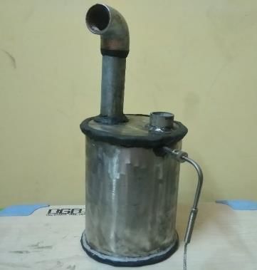
International Research Journal in Engineering and Emerging Technology (IRJEET)

 Volume – 01, Issue – 01, March – 2020
 Table 1. Heat capacity of materials

 Material Heat Capacity (MJ/kg) Material Heat Capacity (MJ/kg)
 PVC 18 Heavy fuel oil 41
 PE 27 Coal 26
 PET 46 Natural gas 36
 PS 41 Milled peat 10
 ABS 35 Paper 17
 *Unit MJ/m3 (0˚ C)
 2.2. PYROLYSIS
 Pyrolysis is a thermochemical decomposition of Organic material at elevated temperatures without
 the participation of oxygen. This involves simultaneous change of chemical and physical phase.
 The pyrolysis process for Waste Engine Oil takes the long chain molecules and breaks or cracks them
 into shorter chains through heat and pressure. Essentially the process is mimicking the natural process
 of the earth to break down carbon into oil which takes millions of years in nature. The pyrolysis
 process does this with intense heat in a closed system in a short amount of time.
 Anhydrous pyrolysis can also be used to produce liquid fuel similar to diesel from Waste Engine Oil
 waste, with a higher cetane value and lower sulphur content than traditional diesel. Using pyrolysis to
 extract fuel from end-of-life Waste Engine Oil is a second-best option after recycling, is
 environmentally preferable to landfill, and can help reduce dependency on foreign fossil fuels and geo-
 extraction. In many industrial applications, the process is done under pressure and at operating
 temperatures above 430 °C (806 °F). For agricultural waste, for example, typical temperatures are 450
 to 550 °C
 2.2.1. THERMAL CRACKING
 Thermal cracking, or pyrolysis, involves the degradation of the organic materials by heating in the
 absence of oxygen. The process is usually conducted at temperatures between 500- 800ºC and results
 in the formation of a carbonized char and a volatile fraction that may be separated into condensable
 hydrocarbon oil and a non-condensable high calorific value gas. The proportion of each fraction and
 their precise composition depends primarily on the nature of the Waste Engine Oil waste but also on
 process conditions. In the case of polyolefin like polyethylene or polypropylene, thermal cracking has
 been reported to proceed through a random scission mechanism that generates a mixture of linear
 olefins and paraffin over a wide range of molecular weights. In other cases, like polystyrene and poly
 methyl Meta acrylate, thermal degradation occurs by a so-called unzipping mechanism that yields a
 high proportion of their constituent monomers.

3. EXPERIMENT SETUP
 Various components are used for the whole process and testing i.e.
 3.1. REACTOR
 The reactor is cylindrical in shape. It consists of two units, one is the main body of side walls and
 base, and other is upper cover. The cover is connected to remaining body by using nut and screws. A
 gasket is provided between the units to stop fumes leak. The middle of upper unit contains a hole
 through which a pipe is welded at 90 degrees to provide as the outlet of fumes. This pipe is connected
 to other pipe using a 90 degrees bend connector. That pipe is bended at 30 degrees halfway through.
 Another smaller hole is provided on upper unit in which thermocouple is inserted.
 The photographic view of the reactor is shown in the figure 2. Around the reactor, heater is fitted.

 www.we-irjeet.com 2019 IRJEET – All Right Reserved 3 | Page
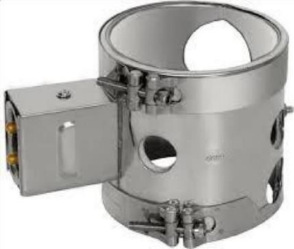
International Research Journal in Engineering and Emerging Technology (IRJEET)

Volume – 01, Issue – 01, March – 2020
 Table 2. Specification of reactor

 SPECIFICATIONS
 Material Mild Steel
 Shape Cylindrical
 Height 250 mm
 Diameter 200 mm
 Thickness 2 mm

 *Unit MJ/m3 (0˚ C) Fig 2. Reactor design

3.2. HEATER
The type of heater used is Ceramic Band Heater. It can provide temperature up to 500℃. They are
fixed on the sides of reactor using screws. An insulating material of glass wool is provided over the
plates. The glass wool help us to trap the heat efficiently and to attain maximum temperature. The
heater having the hole for to insert the thermocouple to measure the temperature of the heater. This
help us to maintain the temperature of the heater to avoid the damage or get burnt of the plates. The
Figure 3 shows the heater used for heating the reactor.
 Table 3. Specification of heater
 SPECIFICATIONS
 Max Temp 500˚ C
 Voltage 230 V
 Power 6000 Watts
 Height 220 mm
 Diameter 210 mm

 *Unit MJ/m3 (0˚ C) Fig 3. Heater design
3.3. CONDENSOR
Two glass condensers were used, one is coil type (Figure 4) and other is double surface ‘Davies’ type
(Figure 5). Both are joined together to increase the efficiency of condensation. A coil condenser is
essentially a "Graham condenser" with an inverted coolant/vapor configuration. It has a spiral coil
running the length of the condenser through which coolant flows, and this coolant coil is jacketed by
the vapor/condensate path.
In double surface condenser, the gases pass through the area which is completely covered by water on
both outer and inner parts. It has increased surface area and effectiveness when compared with the
corresponding Liebig condenser. Inner cooling surface gives a baffling effect, while outer cooling
surface prevents creep and loss of vapor when used with low boiling liquids.

 Fig 4. Coiled type condenser Fig 5. Davies condenser

www.we-irjeet.com 2019 IRJEET – All Right Reserved 4 | Page
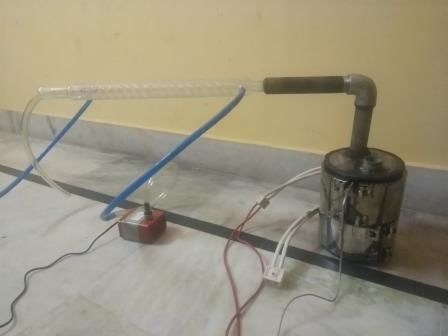
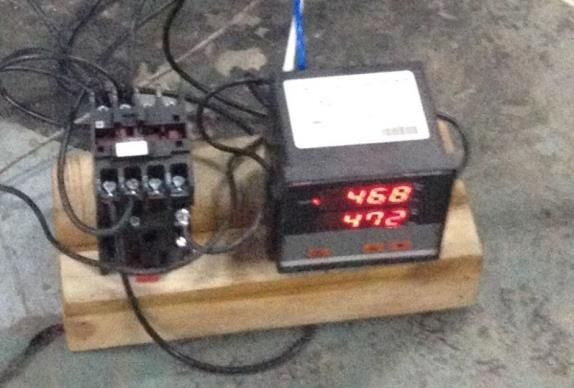
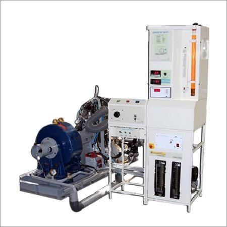
International Research Journal in Engineering and Emerging Technology (IRJEET) Volume – 01, Issue – 01, March – 2020 3.4. TEMPERATURE CONTROL SETUP The setup for monitoring and controlling temperature of reactor and heater consists of: Thermocouple Temperature Indicator Temperature Controller Fig 6. Temperature Controller 4. SYSTEMATIC AND PHOTOGRAPHIC VIEW OF PYROLYSIS SETUP Fig 6. Systematic view Fig 7. Photographic view 5. TESTING SETUP Table 4. Engine Specification SPECIFICATIONS No. of Cylinders 1 No. of Stroke 4 Rated Power 5.2 kW @ 1500 rpm Bore 87.5 mm Stroke 110 mm Compression Ratio 17.5 : 1 Orifice diameter 20 mm Dynamometer arc length 185 mm Injector opening pressure 210 bar Fig 8. Diesel engine test ROG setup www.we-irjeet.com 2019 IRJEET – All Right Reserved 5 | Page
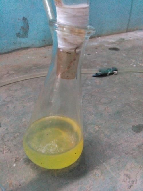
International Research Journal in Engineering and Emerging Technology (IRJEET) Volume – 01, Issue – 01, March – 2020 6. FUEL PRODUCTION The method used for preparation of fuel from Waste Engine Oil is pyrolysis. The reactor having the ceramic band heater fixed on all four side from outside is used for to get high temperature (maximum 550oC). The raw material is put inside the reactor and make the reactor seal tight by using gas kit. Nut and bolts are used for fixing the upper unit on the lower reactor unit. There are different experiment we go through and used different types of Waste Engine Oil for pyrolysis. Some of them are mentioned below. 6.1. PROCEDURE The Waste Engine Oil used for pyrolysis was black in color. Took around 500ml of 15W40 grade. The Waste Engine Oil was put inside the reactor. Gasket is fitted between the cover and bottom unit for perfect sealing. Closed the reactor using nut and bolt. Make sure that reactor is perfectly sealed from the atmosphere. Checked all the connection of heater, temperature controller, thermocouple, temperature indicator. Inserted the thermocouple through the hole on the upper cover to measure temperature inside the reactor (temperature of melt polybags). It was connected with the temperature indicator. Another thermocouple was used to control the temperature of heating plates which was connected with temperature controller unit. Condenser was connected with the pipe come out the reactor. Adaptors were used for reducing and increasing the size for air tight connections. Tap water was used as cooling medium for condensation. Checked all the units and then switched ON the power supply. 6.2.OBSERVATION Initially temperature inside the reactor was at room temperature 31 ˚C. Temperature inside the reactor increases with increase in temperature of heating plates. At 235 ˚C white fumes come from the pipe and get stop at 300 ˚C. Again fumes start to come at 345 ˚C and continue till temperature reaches 450 ˚C. The fumes come out from the reactor are pass through the condensation unit for condensation. The rates of fumes get reduced and stop at temperature 476 ˚C. Heating plate gets burnt due to excess temperature 6.3.RESULT Fig 9. Diesel like fuel collected in beaker www.we-irjeet.com 2019 IRJEET – All Right Reserved 6 | Page
International Research Journal in Engineering and Emerging Technology (IRJEET)

Volume – 01, Issue – 01, March – 2020
7. PROPERTIES OF DIESEL LIKE FUEL
 7.1. FLASH POINT
 The flash point of a flammable fuel is the lowest temperature at which it can form an ignitable
 mixture in air. At this temperature the vapor may cease to burn when the source of ignition is
 removed. The flash point is often used as one descriptive characteristic of liquid fuel, but it is
 also used to describe liquids that are not used intentionally as fuels.
 Table 5. Flash Point
 S. No. DLF Diesel
 1 56 ˚C > 52 ˚C
 7.2. FIRE POINT
 The Fire point of a flammable fuel is the lowest temperature at which it can form an ignitable
 mixture in air. At this temperature the vapor starts burn when the source of ignition is removed.
 Table 6. Fire Point
 S. No. DLF Diesel
 1 64 ˚C > 62 ˚C
 7.3. VISCOCITY
 Viscosity is a measure of a fluid's resistance to flow. It describes the internal friction of a
 moving fluid. A fluid with large viscosity resists motion because its molecular makeup gives it a
 lot of internal friction.

 Fig 10. Variation of Viscosity with Increase in Temperature
 7.4. CALORIFIC VALUE
 The calorific value of any fuel in solid or liquid state can be calculated with the help of Bomb
Calorimeter, by using a simple formula:

 = ( + ) ∗ ( + − ) ∗

Here, m1 and m2 ≥ mass of water and equivalent mass of bomb. T1 and T2 are initial and final
Temperatures. Mf is mass of fuel sample and Tc is radiation losses.

www.we-irjeet.com 2019 IRJEET – All Right Reserved 7 | Page

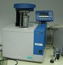
International Research Journal in Engineering and Emerging Technology (IRJEET)

Volume – 01, Issue – 01, March – 2020
7.4.1. BOMB CALORIMETER
 The bomb calorimeter is simple equipment which helps in finding out the calorific value of
fuel, the combustion inside the calorimeter take place at high pressure (30 atm), so the calorimeter is
made up of heavy metals. The pressure inside the bomb is due to the presence of the pumped in
oxygen, this pumped in oxygen will help in the process of combustion. The energy used for the
combustion process in the bomb calorimeter is electrical energy; for each experiment a 2g of sample
is used the sample is filled inside the crucible. The electrical circuit is then completed with the help of
a nichrome wire.
 Table 7. Observation Table
Sample m1 m2 T2 T1 TC CW mf
Diesel 2000g 755g 39 °C 26 °C 0.5 °C 1 2g
DLF 2000g 755g 36 °C 26 °C 0.5 °C 1 2g

 Fig 11. Bomb calorimeter
7.4.2. CALCULATIONS
(2000 + 755)*(0.5 + 29.38 – 26)*1/2 = 10700.32 cal/g
1 cal/g = 4186.79 J/kg
10700.32 cal/g = 44800000 J/kg = 44800 KJ/kg
(2000 + 755)*(0.5 + 28.83 – 26) = 9177.68 cal/g
9177.68 cal/g = 38425000 J/kg = 38425 KJ/kg

 Fig 12. Profile of calorific values of diesel and DLF

www.we-irjeet.com 2019 IRJEET – All Right Reserved 8 | Page
International Research Journal in Engineering and Emerging Technology (IRJEET)

Volume – 01, Issue – 01, March – 2020

 7.5. ENGINE PERFORMANCE FOR DIESEL LIKE FUEL (DLF)
 Table 8. Observation Table

 S. No. Speed Load Fuel Time Engine Cal. T1/T3 T2 T4 T5 T6
 flow Cooling Water Engine
 (rpm) (kg) (Sec)
 (ml) Water Water In
 (Lph)
 W x t (Lph) (˚C)
 1. 1500 0 10 60 1000 250 25 35 32 125 95
 2. 1500 5 10 38 1000 250 25 37 35 187 134
 3. 1500 10 10 25 1000 250 25 40 38 245 170
 4. 1500 15 10 15 1000 250 25 43 40 330 218
Here, T2 is engine water in (˚C), T4 is calorimeter water out (˚C), T5 is exh in (˚C) and T6 is exh out (˚C).
 Table 9. Results
 S.NO. Load Br. Torque Br. Power Fuel Cons. Sp. Fuel Cons. Heat Supplied Brake Thermal
 (kg) (Nm) (kW) (kg/sec) (kg/kW-sec) (kV) Eff. (%)
 1. 0 0 0 0.000142 0 5.4564 0
 2. 5 9.074 1.425 0.000224 0.0001571 8.6072 16.56
 3. 10 18.15 2.905 0.000340 0.000170 13.0645 22.24
 4. 15 27.22 4.280 0.000567 0.000132 21.787 19.64

 7.6.ENGINE PERFORMANCE FOR DIESEL
 Table 10. Observation Table

 S. No. Speed Load Fuel Time Engine Cal. T1/T3 T2 T4 T5 T6
 flow Cooling Water Engine
 (rpm) (kg) (Sec)
 (ml) Water Water In
 (Lph)
 W x t (Lph) (˚C)
 1. 1500 0 5 32.66 1000 250 25 35 32 111 95
 2. 1500 5 5 17.99 1000 250 25 37 35 181 134
 3. 1500 10 5 13.56 1000 250 25 40 38 247 170
 4. 1500 15 5 10.65 1000 250 25 43 40 320 218
Here, T2 is engine water in (˚C), T4 is calorimeter water out (˚C), T5 is exh in (˚C) and T6 is exh out (˚C).
 Table 11. Results
 S.NO. Load Br. Torque Br. Power Fuel Cons. Sp. Fuel Cons. Heat Supplied Brake Thermal
 (kg) (Nm) (kW) (kg/sec) (kg/kW-sec) (kV) Eff. (%)
 1. 0 0 0 0.000123 0 5.3505 0
 2. 5 9.074 1.425 0.000223 0.000156 9.7005 14.68

www.we-irjeet.com 2019 IRJEET – All Right Reserved 9 | Page
International Research Journal in Engineering and Emerging Technology (IRJEET)

Volume – 01, Issue – 01, March – 2020

 3. 10 18.15 2.905 0.000296 0.000102 12.876 22.56
 4. 15 27.22 4.280 0.000377 0.000088 16.399 26.099

 Variation of BSFC with Brake Power
 Diesel DLF
 350
 300
 BSFC (g/kW h)

 250
 200
 150
 100
 50
 0
 0 0.5 1 1.5 2 2.5 3 3.5 4 4.5
 Brake Power (kW)

 Fig 12. Variation of brake specific fuel consumption with brake power

 Variation of Brake Thermal Efficiency with Brake Power
 Diesel DLF
 350
 300
 BSFC (g/kW h)

 250
 200
 150
 100
 50
 0
 0 0.5 1 1.5 2 2.5 3 3.5 4 4.5
 Brake Power (kW)

 Fig 13. Variation of brake thermal efficiency with brake power

 www.we-irjeet.com 2019 IRJEET – All Right Reserved 10 |
 Page
International Research Journal in Engineering and Emerging Technology (IRJEET)

Volume – 01, Issue – 01, March – 2020

 Variation of Exhaust Gas Temperature with Brake Power
 Diesel DLF
 350
 300
 BSFC (g/kW h)

 250
 200
 150
 100
 50
 0
 0 0.5 1 1.5 2 2.5 3 3.5 4 4.5
 Brake Power (kW)

 Fig 14. Variation of exhaust gas temperature with brake power

CONCLUSIONS
 Diesel like fuel is produced and engine performance testing is done. The produced fuel is
having 38425 KJ/kg of calorific value, which is less than as compared to the calorific value of diesel
44800 KJ/kg but can be used effectively in diesel engines.
Waste engine oil can be reused as diesel like fuel and approximately 3/4th of waste engine can be
converted to diesel like fuel easily. It can also be used for domestic purpose and in industry area.
REFERENCES
1] Thermofuel – “ Pyrolysis of waste Waste Engine Oil to produce Liquid Hydrocarbons” Dr. P.V.
 Thorata, Miss. Sandhya Warulkara ,Miss.Harshal Sathone, Head of Department , Assistant Professor of
 Department of ORGANIC Technology, College of engineering and technology, Akola, Maharashtra,
 INDIA, ISSN 2277 – 7164
[2] Using waste Waste Engine Oil oil as a fuel by Naresh Shah and Bhogender
 Sharma, Department of Chemical Engineering
[3] Waste Waste Engine Oil Pyrolysis oil Alternative Fuel for CI Engine – A Review Pawar Harshal R.
 and Lawankar Shailendra M. Department of Mechanical Engineering, GCOE, Amravati, MS, INDIA,
 ISSN 2278 – 9472
[4] Waste Engine Oil to oil Dipak Kumar Shaw, Pranav Sahni, Students of Mechanical Engineering, ITM
 University, Gurgaon, India, ISSN: 2278-1684
[5] Waste Engine Oils pyrolysis and coal coprocesslng with waste Waste Engine Oils by M. S.
 Mulgaonkar, c. H. Kuo, a. R. Tarrer of Chemical engineering department, Auburn University, Auburn.
 Al-36849
[6] Converting Waste Waste Engine Oil to Gasoline-like Fuel at low temperature by Nobiyuki Mikata,
 Jude Onwudiliand Paul T. Williams of Energy and Resource Research Institute, School of Process,
 Materials, Environmental Engineering, University of Leeds
[7] Synthesis of Petroleum-Based Fuel from Waste Waste Engine Oils and Performance Analysis in a CI
 Engine by Christine Cleetus, Shijo Thomas, and Soney Varghese of Department of Mechanical
 Engineering, NIT Calicut, Kerala, India
[8] Waste Waste Engine Oil Oil as a Diesel Fuel in the Diesel Engine by Prof Nilamkumar. S. Patel, Mr.
 Keyur D. Desai
[9] Pyrolysis and catalytic cracking of municipal Waste Engine Oil waste for recovery of gasoline range
 hydrocarbons by Moinuddin Sarker & Saurabh Pandey of department of chemical engineering,
 National institute of technology, Rourkela

 www.we-irjeet.com 2019 IRJEET – All Right Reserved 11 |
 Page
International Research Journal in Engineering and Emerging Technology (IRJEET)

Volume – 01, Issue – 01, March – 2020
[10] Conversion of Waste Engine Oil Wastes into Fuels by Antony Raja and Advaith Murali, Department of
 Chemical Engineering, Sri Venkateswara College of Engineering, Sriperumbudur, India, ISSN 1934-
 895
[11] http://www.Waste Engine Oil2oil.com/site/home
[12] http://en.wikipedia.org/wiki/Pyrolysis
[13] http://en.wikipedia.org/wiki/Waste Engine Oil_recycling
[14] http://www.inspirationgreen.com/Waste Engine Oil-waste-as-fuel.html
[15] http://www.cynarplc.com/cynar-technology
[16] http://www.ntepa.nt.gov.au/waste-pollution/Waste Engine Oil-bagban/enviroimpacts

 www.we-irjeet.com 2019 IRJEET – All Right Reserved 12 |
 Page
You can also read