Project work presentation - Project Title
←
→
Page content transcription
If your browser does not render page correctly, please read the page content below
Project work presentation

Project Title:   Microcontroller based power controller for an Electric
                    Vehicle.
Project Index:   122

By:              Eric Bulimo Ubaga
                 F17/1451/2011

Supervisor:      Mr. C. Ombura.
Examiner:        Dr. Dharma.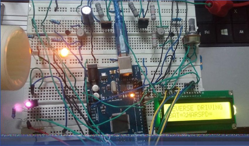
Introduction
An electric vehicle (EV) is a vehicle that is powered, at least in part, by electricity
This project, therefore, seeks to design such a controller system that is microprocessor
based to monitor the power flow of the EV i.e. monitoring the battery conditions and
controlling the flow of power from the battery to the traction motor.
Key issues addressed in the project include:
1. What is an Electric Vehicle (EV)?
2. Why an EV?
3. Possible implementation.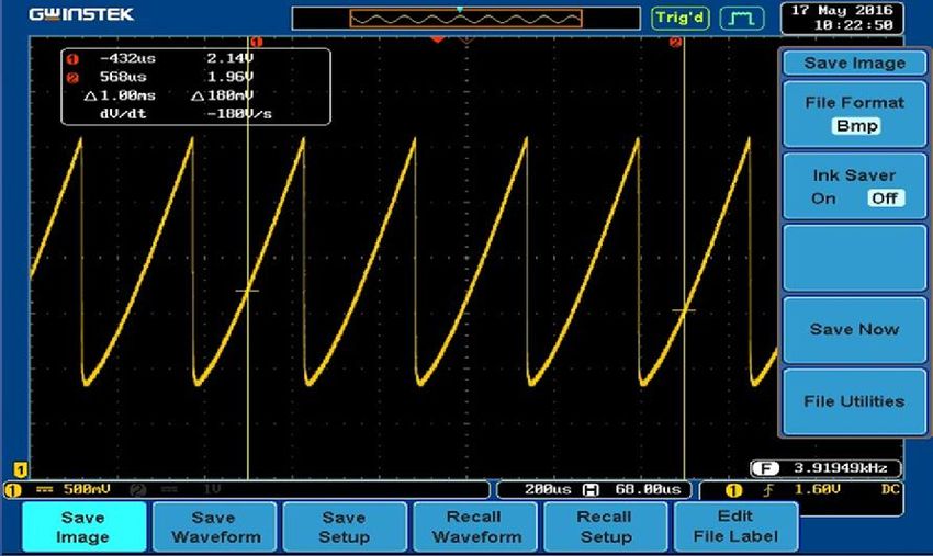
Specifications
the power controller was to be designed meeting the following conditions:
1. Drive a 600W motor. 350W motor was however used in implementation.
2. Must be microprocessor based.
3. Drive an EV while minimizing the cost of production.
4. Determine the state of charge (SOC) of the battery and indicate its’ capacity.
Electric Vehicle and Applications
The controller take power and delivers it to the motor. The accelerator pedal hooks to a
pair of potentiometers that provide the signal that tells the controller how much power
it is supposed to deliver.
Has mainly three components:
i. The drive system
ii. The control system
iii. The battery pack system
Electric traction has been in application though mainly in forklifts. Over the years,
electric traction study and research has been intensified and its application be used in
many different ways such as electric vehicle, electric train, electric motorcycles,
electric scooter and electric traction elevators
Design

 Divided into Circuitry and program.
 The motor picked on was a dc motor, 350 Watts
      A.   Circuitry
The skeleton of the designed circuit was the h-bridge
  H- Bridge.
 An H-Bridge or full bridge converter is a switching configuration
 composed of four switches in this case MOSFETs in an arrangement that
 resembles an H.
  H- bridge enables voltage to be applied across a load in either direction.


Design …. Circuitry.
While designing this circuit, a choice had to be made between the IGBT and power
MOSFET.
Power MOSFETS have a much higher switching frequency capability than do
IGBTs. They do not have as much capability for high voltage and high current
applications, and tend to be used at voltages lower than 250V and less than 500W.
 Since this project is about design of a 24V, DC motor control to be used in electric
vehicle MOSFET is the ideal choice. Also MOSFET being a voltage controlled
device, it can be driven directly from CMOS or TTL logic and the same gate signal
can be applied to diagonally opposite switches since the gate drive current required is
very low.
Design…. PWM.
 Pulse Width Modulation (PWM)
Pulse-width modulation uses a square wave whose pulse width is modulated resulting
in the variation of the average value of the waveform.
The average of voltage that supply to DC motor is given by,
  =   / ∗ in
Where Vave = average voltage supply to DC motor
    ton = time ON of switches
     T = period of PWM
     ton /T = DC, duty cycle
In PWM method, operating power to the motors is turned on and off to modulate the
current to the motor. The duty cycle determines the speed the motor
The Pulse Width Modulation (PWM) in microcontroller is used to control duty cycle of
DC motor drive.
Design…. PWM
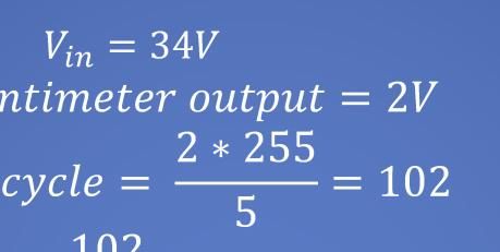
Example:
=
=
2 ∗ 255
= = 102
5
102
= ∗ 34 = 13. .
255
The PWM is effected through the optocoupler that is put on the ground side of the
H-Bridge circuit.Design….. Software. he microcontroller was programmed in the Arduino language that is based on C programming nguage. he flow chart showing the working algorithm inside the microcontroller is shown below. ogram begins by initializing the microcontroller pins and the display unit. icrocontroller constantly checks for the battery capacity allowing for movement only when the attery has a percentage capacity greater than 0. This translates to input greater than 30V.
Design…. Flow chart
                            start

               INITIALIZE THE MICROCONTROLLER
                    INITIALIZE THE VARIABLES
                INITIALIZE THE LCD DISPLAY UNIT

                    CHECK BATTERY SOC.            NO
                     ENOUGH CHARGE?

                                    YES
                    DISPLAY DRIVING MODE
              DISPLAY STATE OF BATTERY CHARGE
                    ENGAGE DRIVING GEAR

                                                  NO
                       CHECK IF THE
                      ACCELERATOR IS
       A                 PRESSED                       C
Design …. Flowchart.
A B C D
YES
PRINT SPEED SET THE INPUT PINS TO ZERO
GOOD CHECK BATTERY
CAPACITY
LESS
DON’T RUN
THE MOTORResults.. the constructed controller was tested and found to drive a 350W DC motor. Some of the results are shown below. On the time of testing, the speed module had not yet been completed. When driving the motor in reverse, the yellow LED lights as shown below.
Results … waveforms. The forward and reverse waveforms are similar and were
Closing…
Microcontroller gives out a perfect square wave that is varied by the
variable resistor acting as acceleration pedal.
The controller is able to run the motor.
The output of the H-Bridge was not a perfect square wave.
In overall the main objectives of the project were obtained .
The greatest limitation was time.
You can also read