Changzhou Mantis Vehicle Co., Ltd - S5 LCD Display (Scooters Only) User Manual V. 2016 - TRIPEBIKE.IT
←
→
Page content transcription
If your browser does not render page correctly, please read the page content below
CMS F16 ITALIA - GRUPPO TELEGRAM - https://t.me/cmsf16italia
Changzhou Mantis Vehicle Co., Ltd.
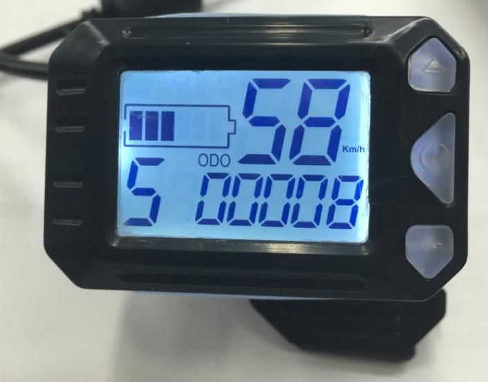
S5 LCD Display (Scooters Only)
User Manual V. 2016
1. Exterior Parameters
Casing Material: ABS
Display Material: High Hardness Acrylic (the same hardness value as
tempered glass).
Front View Side View
1Throttle View Brake Front View
Brake Side View Brake Throttle View
880 Supporter
2. Operating Voltage and Connectors
a. Operating Voltage: DC24V / 36V Compatible, 36/48V Compatible (set by
the control panel), 60V. Other operating voltage can be customized.
b. Connectors:
Standard connector sequence
Controller Connector Panel Outlet Terminal Wire Connector
Standard Connector Sequence Table
Sequence No. Wire Colour Functions
1 Red(VCC) Panel Power Cord
2 Blue(K) Controller Power Cord
3 Black(GND) Panel Ground Wire
24 Green(RX) Panel Data Receiving Wire
5 Yellow(TX) Panel Data Sending Wire
Some displays use waterproof connectors, the customer may not be able to
identify the internal wire color.
3. Functions
a. Display
Speed Display, Battery Level Display, Error Indication, Total Mileage, Single
Mileage
b. Control and Settings
Power Switch, Wheel Diameter Setting, Idleness Time Setting for
Auto-Hibernation, Backlight Brightness Setting, Start Mode Setting, Drive
Mode Setting, Voltage Level Setting, Controller Current Limit Setting
c. Communications Protocol: UART
Display Readings (display at start for 1 second)
Display Details
3.1 Battery Level
3.2 Multi-Functions Display
Total Mileage: ODO
Single Mileage: DIS (Unit: MILE/KM)
Code Indication Note
(Decimal)
0 Normal
1 Reserved
32 Brake
3 Power Sensor Error (riding mark) Not realizable
4 Cruise at 6km/h
5 Real-time Cruise
6 Low Battery Voltage
7 Motor Error
8 Handlebar Error
9 Controller Error
10 Communications Receiving Error
11 Communications Sending Error
12 BMS Communications Error
13 Light Error
3. 3 Speed Display
Measuring Unit: MPH or KM/H
The speed signal is generated from the Hall signal in the motor and is sent
to the panel by the controller.
The panel will calculate the actual travelling speed based on the wheel
diameter and signal data (number of magnet steel is needed for Hall motors).
3.4 PAS Level
Power Assist Level 1 / 2 / 3.
3.5 Vehicle Status Display
:Setting Mode :Digital Voltage :Brake Indicator
:Motor Failure :Throttle Failure :Wheel Diameter
:Light :Controller Failure
8. Settings
P01: Backlight Brightness (1: darkest; 3: brightest)
P02: Mileage Unit (0: KM; 1: MILE)
4P03: Voltage Class: 24V (default) /36V / 48V
P04: Hibernation Time (0: never, other figures refer to the hibernation time)
Unit: minute
P05: Power Gear – 0/3 Gear Mode: Gear 1: 2V Gear 2: 3V Gear 3: 4V
1/5 Gear Mode: Gear 1: 2V Gear 2: 2.5V Gear 3: 4V
Gear 4: 3.5V Gear 5: 4V
P06: Wheel Diameter Unit: inch Precision: 0.1
P07: Magnet Steel Number for Speed Test Range: 1-100
P08: Speed Limit
Range: 0-50km/h, parameter 50 indicates no speed limit.
1. Non-communications status (panel-controlled)
When the current speed exceeds the speed limit, the PWM output will
be shut down; when the current speed falls to lower than the speed limit, the
PWM output will be activated and the driving speed will be set as the current
speed ±1km/h (only applies to assist power speed, not applicable to the
handlebar speed).
2. Communications status (controller-controlled)
The driving speed will be kept constant as the limited value.
Error Value: ±1km/h (applicable to both the assist power/handlebar
speed)
Note: The above-mentioned values are measured by metric unit
(kilometers). When the measuring unit is switched to imperial unit (mile), the
speed value displayed on the panel will be automatically switched to
corresponding imperial unit, however the speed limit value in the imperial unit
interface won’t change accordingly.
P09: Zero / Non-zero Start Setting:
0: Zero Start
1: Non-zero Start
P10: Drive Mode Setting
0: Power Drive – The specific gear of the assist drive decides the assist
power value. In this status the handlebar does not work.
1: Electric Drive – The vehicle is driven by the handlebar. In this status the
power gear does not work.
2: Power Drive + Electric Drive – Electric drive does not work in zero-start
status.
P12: Assist Power Intensity Range: 0-5
P13: Power Magnet Steel Number: 5 / 8 / 12pcs
P14: Current Limit Value: 12A by default; Range: 1-20A
P15: Unspecified
P16: ODO Zero-Out: Long press the upper key for 5 seconds and ODO will zero
out.
4. Introduction of Keys
1. Short press ON/OFF to turn on the panel when it’s off. Short press ON/OFF to
switch the interface in ODO/TRIP/RM/TM/ERRO mode when the panel is on.
52. Long press ON/OFF to turn off the panel when it’s on. Short press the up key
+ to increase the PAS level, short press the down key - to decrease the PAS
level.
3. Long press up key + to adjust the parameter.
In the setting interface, short press ON/OFF to switch parameters, and long
press MODE to add (“A” on the left side) /minus (“d” on the left side) the value.
After the change, short press on/off to switch to the next parameter and save
the last parameter, or long press MODE and the parameter will stop blinking and
be saved. Long press ON/OFF+MODE to exit parameter setting interface, or wait
for 10 seconds and automatically exit the mode.
4. The throttle is used to adjust the motor rotational speed. Turn it from top
down and the motor will accelerate, release the lever the motor will decelerate.
Note: Due to product upgrade, the product you purchased may be
slightly different from the descriptions in this user manual, and this
won’t affect normal usage.
CMS F16 ITALIA
Gruppo Telegram
https://t.me/cmsf16italia
Iscriviti su CMS F16 ITALIA. Gruppo dedicato agli appassionati di
questa fantastica bici ed anche delle sue rivali.
Buona permanenza!
6You can also read