POSIFLEX USER INSTALLATION GUIDE - Red River Software
←
→
Page content transcription
If your browser does not render page correctly, please read the page content below
POSIFLEX USER INSTALLATION GUIDE

Copyright© 2013 Triple E Technologies. All rights reserved.
POSIFLEX USER INSTALLATION GUIDE
Manufacturer Supplied Components:
            1.   POSIFlex KS7215 touchhead
            2.   Triple E Technologies Posiflex Installation Card
            3.   Keyboard
            4.   Mouse
            5.   Power Cord
            6.   Display Port to DVI Adapter
            7.   Resource media DVD
            8.   FCC Required Safety and Regulatory Documentation
            9.   Posiflex Cables and Components in accordance with product specification.*

OVERVIEW
Each new Posiflex system installation is shipped with the Manufacturer Supplied Components listed
above. For best results, read and become familiar with the product documentation included as well as
the product components included with the installation shipment.
The product includes a lithium battery. Always follow local environmental rules and regulations
pertaining to the disposal of used batteries. Always replace the battery only with a battery of the same
type.
                                                    NOTE
             There is a risk of explosion in the event that the lithium battery is replaced by
             an incorrect type.

INSTALL GUIDE
The Posiflex system will be shipped partially assembled. Components and Peripherals will be connected
to the unit with provided fasteners, and electronic components will be connected through the
power/connector console (See Page 6, Figure 14). Pass through all connecting cables through the base
as set forth on Page 10.

PARTS IDENTIFICATION
            1.   Main Display Unit
            2.   Touch/LCD Panel
            3.   Power Indicator
            4.   Gen 5 Base Stand
            5.   Attachment Screw Holes for PDC71648 Customer Display Unit (CDU)[??]
            6.   Hard Disk Drive (HDD) Cover
            7.   Power Switch

                                                     2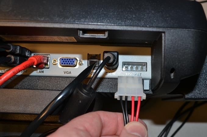
8.    Brightness Control Button “+”
            9.    Brightness Control Button “-“
            10.   USB Ports
            11.   Base Stand
            12.   Compression lock for base stand cover
            13.   Cable exit
            14.   Cable groove
            15.   Cable exit
            16.   Cable holder
            17.   Bottom Plate
            18.   Cable Passage in bottom plate
            19.   Rubber feet with bottom plate fastening screw

CONNECTING CASH DRAWER
The RJ11 connector in I/O area of a KS6915/6917/7215/7217 system can be used for controlling most of
the common cash drawers available on the market.
However, it is most recommended to use Posiflex CR-2200 or CR-2210 or CR-3100 or CR-4000 or CR-
4100 or CR-6300 for best compliance in operating the opening mechanism and to monitor the “drawer
open” status.
The connector cable for the Cash Drawer has a 6-pole plug at one end and an 8-pole plug at the other.
The 8-pole plug should be inserted into the connector of the cash drawer labeled “Signal.” The 6-pole
plug should be inserted in the connector marked “CR” which can found in the main connection area in
the system. The user may also purchase the optional 2-in-1 cash drawer control cable to control 2 cash
drawers in 1 port. It has a 6-pole plug at one end and two 8-pole plugs at the other. The 6-pole plug
should be inserted in the connector marked “CR” found in the I/O area in the system. Each 8-pole plug
should be inserted into the connector marked “signal cable from POS Printer” at the rear of one of the
cash drawers.

                                                    3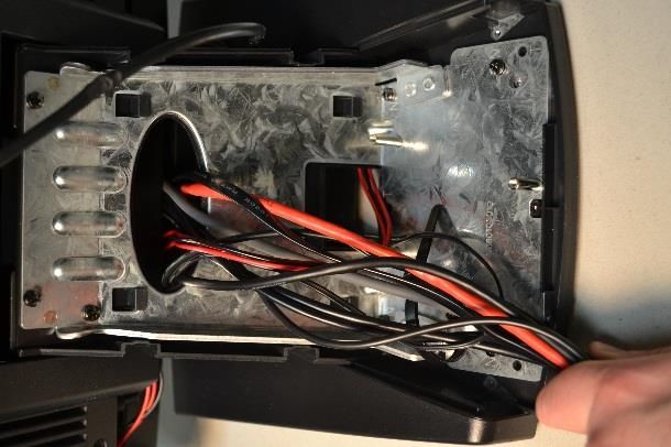
FINAL ASSEMBLY AND INSTALLATION INSTRUCTIONS

                                                   2. Remove the two screws that attach the
                                                      panel to the touchscreen.

1. If you wish to install an optional card
   reader, locate the accessory panel on the
   right hand side of the touchscreen.

                                                   3. Remove the panel. The connector for the
                                                      card reader will be visible.

                                                   4. Locate the port on the card reader.

                                               4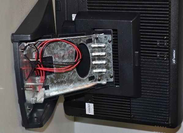
5. Insert the connector from the touchscreen       7. Locate the cable cover at the rear of the
   into the port on the card reader.                  touchscreen base.

6. Attach the card reader to the touchscreen
   with the same two screws previously             8. Remove the cover by gently prying up on
   removed.                                           the four tabs holding it in place and lift
                                                      away.

                                               5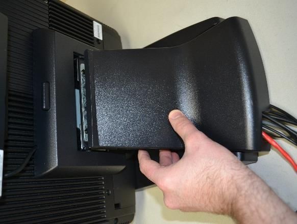
9. The metal stand and back-up battery cable         12. Locate the two locking tabs for the port
   should now be visible.                                cover. Gently press down on these tabs and
                                                         slide the cover away from the touchscreen.

                                                     13. You should now be looking at the accessory
                                                         ports at the bottom of the touchscreen.

10. Swivel the touchscreen back to access the
    port cover at the bottom of the screen.

                                                     14. Locate the ‘COM1’ port to the left of the
                                                         accessory ports.

11. You should now be looking at the bottom of
    the touchscreen.

                                                     NOTE: ‘COM1’ must either have an accessory or
                                                     the COM terminator connected plugged into it.

                                                                                 or

                                                 6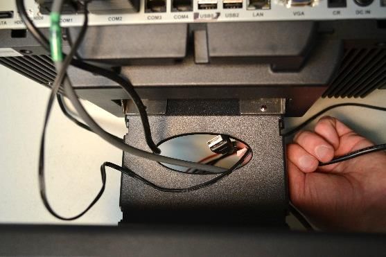
15. In this example, an optional customer            18. Lift the touchscreen up and away from the
    display will be connected to ‘COM1’. The             base.
    device is then mounted on the rear of the
    touchscreen with two screws.

                                                     19. Note the touchscreen is connected to the
16. Locate the touchscreen release button on
                                                         base unit by four pins that key into
    the top rear of of the base.
                                                         corresponding slots on the base unit.

                                                     20. Locate the customer display cable notch on
17. Position one hand underneath the                     the top of the base unit.
    touchscreen. Press the release button with
    your other hand.

                                                 7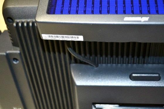
21. Place the customer display cable in the            23. Make sure the customer display cable is
    notch, and route the cable through to the              properly routed through the notch and all
    cable organizer at the bottom of the base              four pins are properly seated in their
    unit.                                                  corresponding slots on the base unit.

                                                       24. Connect the customer display cable to the
                                                           ‘COM1’ port.

22. Key the pins of the touchscreen into the
    slots on the base unit and slide the
    touchscreen back into place. You will hear a
    ‘click’ when the unit is fully seated.

                                                       25. For all devices that will be connected to the
                                                           touchscreen (except the customer display),
                                                           route their cables through the oval opening
                                                           in the metal stand of the touchscreen.

                                                   8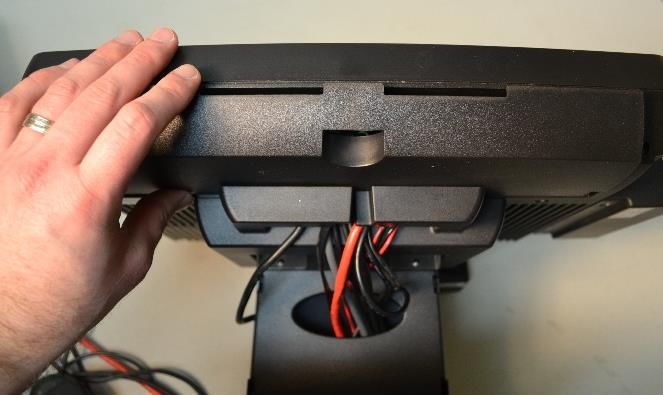
26. Connect the hand scanner to ‘COM2’.                 30. Connect the cash drawer cable to the ‘CR’
                                                            port.

27. Insert the power supply plug into the hand
    scanner plug.                                       31. Connect the touchscreen’s power supply
                                                            cable to the ‘DC IN’ port

28. Connect all USB devices, such as a
    keyboard, mouse, signature capture device,
    etc. to the USB ports.                              32. Connect the battery back-up to the ‘12V
                                                            BAT’ port.

29. Insert the network cable into the ‘LAN’ port.

                                                    9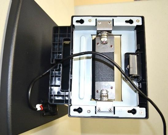
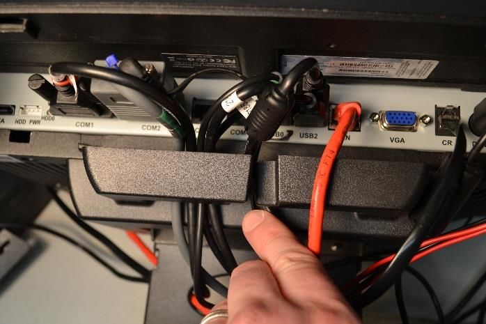
33. Tuck all cables into the cable organizer (if so 35. At the rear of the touchscreen, gather all of
desired). the cables into the lower-left-hand corner
of the base (except the customer display
cable).
34. Slide the cable cover back into place. Swivel
the touchscreen back into an upright
position.
36. Press the cable cover back into place
making sure the customer display cable
remains clear if equipped. Power on all
peripheral devices at this time.
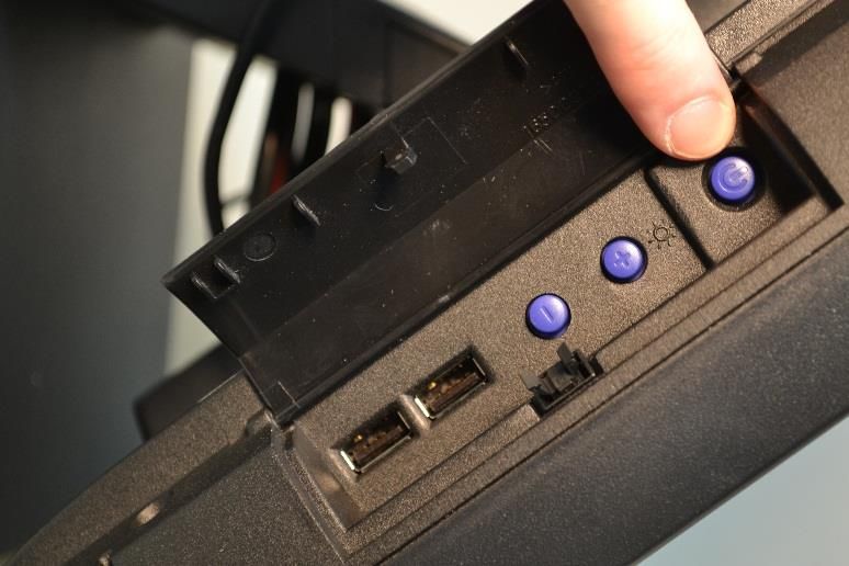
1037. Locate the button cover panel on the left- 39. Contact Triple E Technologies to complete
hand side of the touchscreen. Press in the the set-up and install of your POSIFLEX
center of the panel to open. device.
38. Locate the power button and press it. This
will power on the touchscreen.
11You can also read