HVDC Submarine Power Cables in the World - State-of-the-Art Knowledge - JRC ...
←
→
Page content transcription
If your browser does not render page correctly, please read the page content below
HVDC Submarine Power Cables
in the World

                 State-of-the-Art Knowledge

                 Authors: Mircea Ardelean, Philip Minnebo

                 Forename(s) Surname(s)

                 2015

                                          Report EUR 27527 EN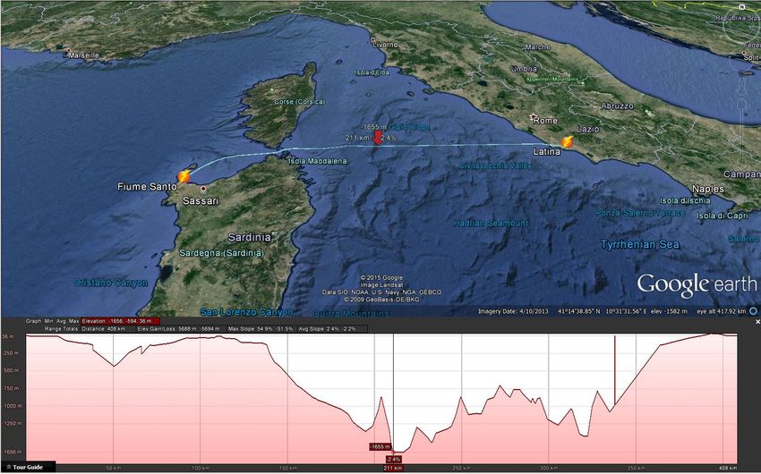
HVDC Submarine Power Cables
in the World
This publication is a Technical report by the Joint Research Centre, the European Commission’s in-house science
service. It aims to provide evidence-based scientific support to the European policy-making process. The scientific
output expressed does not imply a policy position of the European Commission. Neither the European
Commission nor any person acting on behalf of the Commission is responsible for the use which might be made
of this publication.

JRC Science Hub
https://ec.europa.eu/jrc

JRC97720

EUR 27527 EN

ISBN 978-92-79-52785-2 (PDF)
ISBN 978-92-79-52786-9 (print)

ISSN 1831-9424 (online)
ISSN 1018-5593 (print)

doi: 10.2790/023689 (online)
doi: 10.2790/957356 (print)

© European Union, 2015

Reproduction is authorised provided the source is acknowledged.

Printed in Netherlands

All images © European Union 2015, unless otherwise specified

How to cite: Ardelean, M., Minnebo, P.; 2015; HVDC Submarine Power Cables in the World; EUR 27527 EN; doi:
10.2790/95735
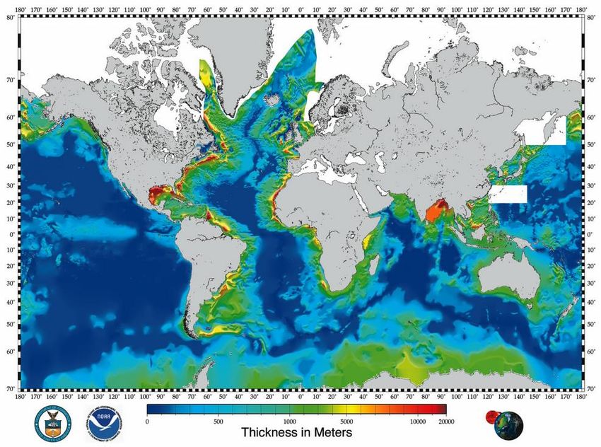
Table of Contents

Executive summary ........................................................................................................................................ 6
1.      Objectives of the report ...................................................................................................................... 8
2.      The power system .................................................................................................................................. 9
     2.1 AC and DC...................................................................................................................................... 9
     2.2 Generation, transmission and distribution ................................................................................... 9
     2.3 Bulk electricity transmission with HVDC power systems............................................................ 11
        2.3.1 HVDC versus HVAC ............................................................................................................... 11
        2.3.2 HVDC configurations ............................................................................................................ 13
        2.3.3 Link with the grid: the converter station ............................................................................. 15
3.      HVDC submarine power cables in the world ..............................................................................17
     3.1 Geographical distribution ........................................................................................................... 17
     3.2 Spatial context ............................................................................................................................ 18
        3.2.1 Geological and path survey .................................................................................................. 18
        3.2.2 Water depth and subsea bed topography ........................................................................... 19
        3.2.3 Geological structure and lithology ....................................................................................... 23
        3.2.4 Geodynamic processes ........................................................................................................ 25
        3.2.5 Sea currents, waves ............................................................................................................. 27
        3.2.6 Temperature, salinity, corrosion.......................................................................................... 28
     3.3 Technology used and materials .................................................................................................. 31
        3.3.1 HVDC cable ........................................................................................................................... 31
        3.3.2 Cable structure, materials and properties ........................................................................... 33
        3.3.3 Convertors............................................................................................................................ 36
     3.4 Installing the cable ...................................................................................................................... 38
        3.4.1 Laying the cable ................................................................................................................... 38
        3.4.2 Protection measures ............................................................................................................ 41
        3.4.3 Maintenance ........................................................................................................................ 43
        3.4.4 Cable lifespan ....................................................................................................................... 44
4.      Reliability and accident risks ..........................................................................................................45
5.      Environmental issues ......................................................................................................................... 47
6.      Long cable examples........................................................................................................................... 50
     6.1 Existing cables ............................................................................................................................. 50
        6.1.1 NorNed – the longest up-to-date power submarine cable.................................................. 50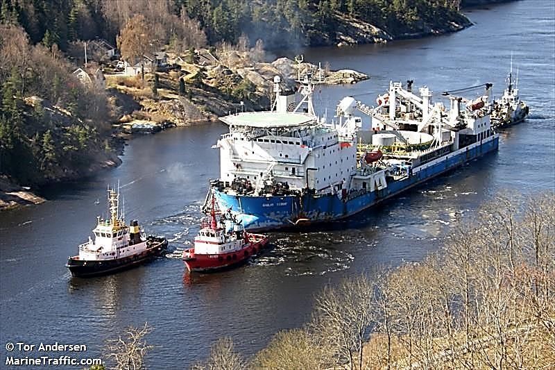
6.1.2 SAPEI – the deepest up-to-date power submarine cable .................................................... 52
        6.1.3. Kii Channel HVDC – the most powerful submarine HVDC cable......................................... 55
    6.2 Planned cables ............................................................................................................................ 56
        6.2.1 NSN Link and NorthConnect ................................................................................................ 56
        6.2.2 Nord.Link and NorGer .......................................................................................................... 57
        6.2.3 IceLink HVDC power cable ................................................................................................... 58
Conclusions ..................................................................................................................................................... 61
References ....................................................................................................................................................... 62
Annex 1 - List of main existing submarine power cables in the World ....................................65
Annex 2 - Glossary .......................................................................................................................................68
List of figures ..................................................................................................................................................... 75
List of tables ...................................................................................................................................................... 77
Executive summary
"Offshore Transnational Grids - Technical and Geopolitical Implications" (acronym OTG) is a JRC
Exploratory Research Project that runs from 1 January 2015 until 31 December 2016. The
objective of the project is to identify and analyse the technical and geopolitical challenges for
building an offshore electricity transmission interconnection between Europe and North America.
This science-for-policy report is the first deliverable of the OTG project. It provides an extensive
study on the availability of the technologies required for the realisation of a High Voltage Direct
Current (HVDC) interconnection between the European and North American Alternating Current (AC)
transmission grids.
An introduction on HVDC transmission systems is given. This implies a discussion on the monopolar,
bipolar and back-to-back configurations. Also the connection with AC grids, i.e. the converter
station, is treated.
Further, attention is paid to the spatial context of laying a HVDC submarine power cable.
Information is provided regarding geological and path surveys, subsea bed topography, geological
structure and lithology. Geodynamic processes, sea currents, waves as well as temperature and
salinity are also discussed.
Technologies and materials used to produce HVDC submarine cables are presented. Different cable
types are shown.
Special attention is given to the installation of HVDC submarine cables. Techniques for laying a
cable are discussed. Also issues such as protection measures and maintenance aspects are dealt
with. The operation of HVDC submarine cable is treated as well.
Reliability and accident risk issues are discussed in a dedicated paragraph as well as environmental
aspects.
A complete, comprehensive chapter is spent on existing and planned HVDC submarine
interconnectors. Emphasis is given the longest and deepest examples. An extensive list of these
cables with relevant data is given in Annex 1.
The report ends with a set of conclusions, primarily pointing at the following steps of the OTG
project. Shortly, they are as follows:
the HVDC submarine power cable technology is now mature;
the experience in laying the cable on the seafloor is inherited and adapted from the much
older technology of telecommunication submarine cables;
6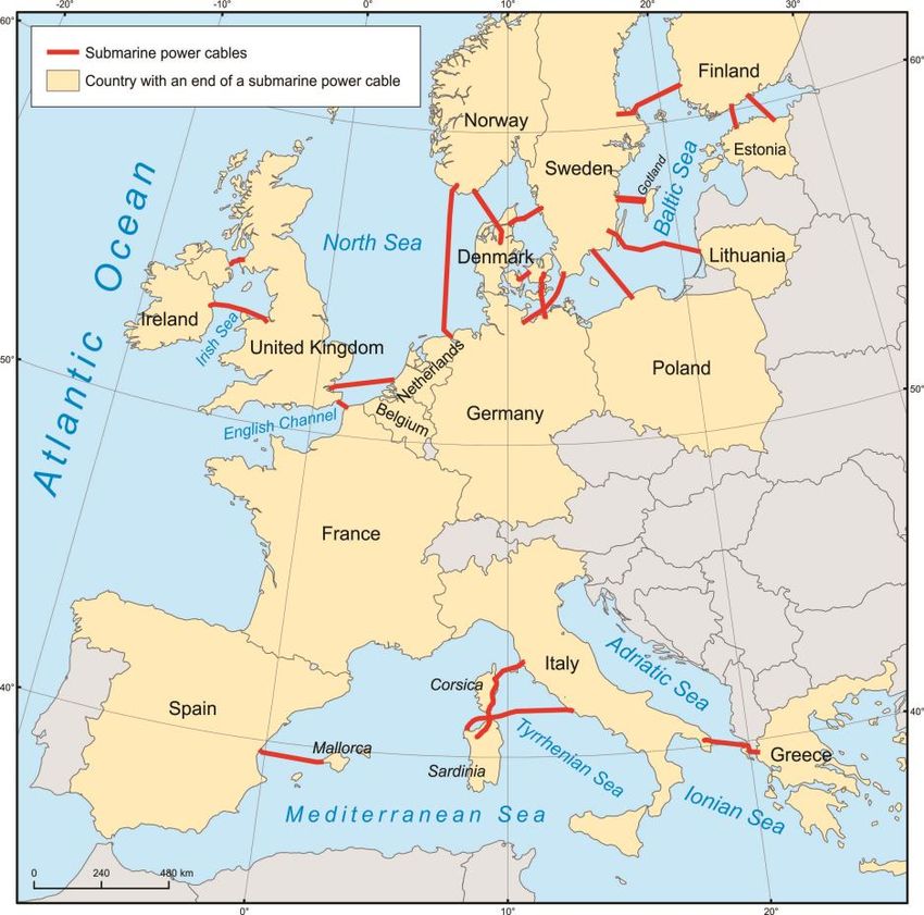
Europe is the leading region in both the length and number of cables having the longest
one, the deepest one and one of the most powerful cables; the majority of manufacturers
and sea-laying cable operators originate here;
mass-impregnated cables are the most used but a new generation of extruded cables are
gaining field;
first submarine power cables used a monopolar configuration but the newly built ones are
predominantly bipolar.
7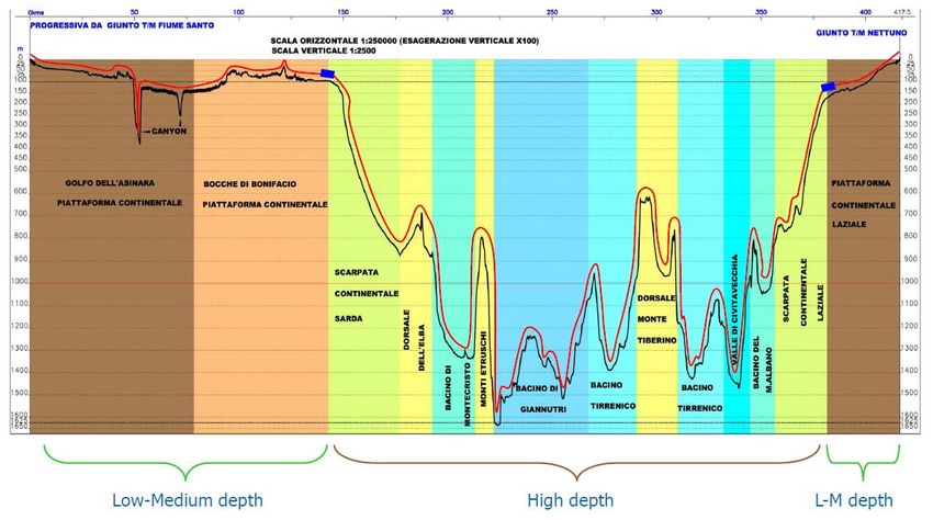
1. Objectives of the report
Our world becomes more and more energetically hungry. Consumption tends to spread and level
across territory but the main sources of energy are likely to remain localized. The growing
integration of intermittent renewable sources of energy (wind) even increases the need for
transferring electric energy over long distances, which may include sea crossings. One of the
solutions available for bulk electric power transmission across large distances encompassing wide
and deep water bodies is using submarine power cables. This technology can be considered as
already mature with various examples of cables operating reliably for decades. However innovation
and development have occurred at a high rate during last years. As more cable lines are under
construction and many more are planned the landscape of submarine power cables is increasingly
expanding and diversified. It certainly deserves a state-of-the-art study.

The report is the first deliverable of the “Offshore Transnational Grid” (OTG) work package, which is
intended to identify and analyse the engineering and geopolitical challenges for building a
transcontinental energy interconnection between Europe and North America.

The scope of the report is to examine the present-day technologies used for submarine power
cables.

It is particularly intended to offer a picture of the state-of-the-art of the High Voltage Direct
Current (HVDC) submarine cables in the world.

The report will not deal however with short distance HVDC power cables that connect off-shore
wind farms or oil extraction platforms to the continent. The locations, number and length of these
cables are not present in the lists or maps of the report. Nonetheless the lessons learned from
building and laying the cable along with technical solutions found are presented in the report.

It is also out of the scope of the report to analyse the economics and power markets that make the
cables workable.

8
2. The power system

2.1 AC and DC
Conventional electrical current may take two forms: Alternating Current (AC) and Direct Current
(DC).
AC is produced by placing a coil of wire into a revolving magnetic field. This is the principle used in
most of the power plants running today: hydro, thermal (coal, gas, nuclear), wind and tidal. Using
one coil results in single-phase AC and using three coils results in three-phase current. Most of the
power plants produce three-phase AC. AC flows in one direction for half a period and then switches
direction for the next half a period. This continuous sinusoidal oscillation takes place with a certain
frequency (the number of cycles occurring in one second). In European grids the standard frequency
is 50 Hz.
DC always flows in the same direction. It is produced by batteries, solar cells and fuel cells. There
are also DC generators working on the principle of electromagnetic induction but they are not the
norm in power production. DC produced in photovoltaic panels (and parks) are turned into AC
current and then fed to the grid.
The type of the current has influence on its transmission in respect to the voltage used, the
capacity of the line (the amount of transferred power), the maximum length of the line and the
intermediate electric equipment used. The advantage of AC over DC is that in AC transformers can
be used to step up or down the voltage level. DC current is however more suitable for bulk
transmission over long distances than AC where the losses are higher.

2.2 Generation, transmission and distribution
Electricity is produced in power plants and then carried over often long distances at high voltages
by the transmission grid, which steps down at the level of the distribution network, bringing the
electric power to the consumer (Fig.1).

This is the classical scheme that worked for many decades and still represents the norm for most
of the regions in the world. As stated above most of the power plants produce electricity as AC and
the entire system uses this current type afterwards since its voltage can be stepped up or down
very easily by the use of transformers. Commonly there have always been a rather small number
of power plants located close to the energy source (coal mines, rivers) or close to large human
settlements, allowing local consumption. Gradually more generation units have been built and
linked together using a grid of high voltage lines called the transmission system. Its role is to
transfer large quantities of electricity sometimes over long distances in order to equilibrate and
stabilize the power system in case of local increase of demand or sudden drop of generation. This

                                                                                                     9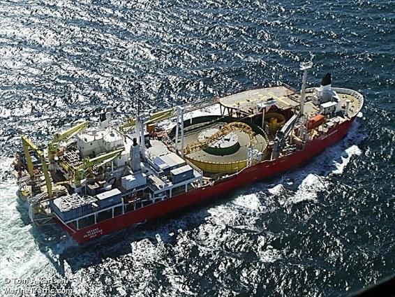
management of this task is assumed by organizations called Transmission System Operators
(TSOs), in most cases state-owned companies.

                Fig. 1– Generation, transmission and distribution of electricity (Source: suptech.com)

As the consumer uses electricity at low voltage, stepping down the voltage and bringing the
electricity in homes, offices or factories is done using a dense network of lines, which compose the
distribution system. Distribution System Operators (DSOs) are in charge of operating this level.
They can be of private, public national or municipal or shared ownership.
Lately this scheme has started to be challenged by the advent of new technologies and alternative
spatial and functional layouts. The rise of renewable sources of energy with high intermittency
(wind, solar) and the arrival of the concept of prosumer (producer and consumer at the same time)
have changed the technical and market landscape demanding new adjustments to the grid. In this
scheme large quantities of electric power produced from clean sources might be fed into the grid
at moments when demand is low or the same unit (e.g. a house with PV panels) feeds but also
takes electricity to/from the grid. For the first case the solution is building the infrastructure for
transferring great quantities of electric power over large distances where they might be needed of
(e.g. in another time zone or another climate area). For the second case the solution is
strengthening the grid in order to cope with bidirectional flows of electricity.
As most of the power plants produce electricity as AC, in order to transmit the power as DC the
current must be converted from one type into the other. This is done in converter stations placed at
each end of the DC transmission line. The cost benefit of DC over AC is noticeable for lines over
600 km long.
The electric power system is a real time system. This means that the electricity produced is
instantly consumed. Actually the need of electricity drives the pattern of generation so that the
power plants must be turned on or off accordingly. Electricity cannot be stored "easily" like water or
gas so a good management of the network is required.

10
2.3 Bulk electricity transmission with HVDC power systems
2.3.1 HVDC versus HVAC
There are two main ways for the transmission of large quantities of electric energy over long
distances: High Voltage Alternating Current (HVAC) and High Voltage Direct Current (HVDC). High
Voltage (HV, including here also Extra-High Voltage – EHV – and Ultra-High Voltage – UHV) is
considered to cover the range of 35 kV – 800 kV and even beyond this in the future.
High voltages allow efficient transmission of large quantities of electric power over long distances.
The higher the voltage is, the lower the dissipative losses are. These losses also depend
significantly on the type of conductor used, the length and the cross section of the line and the
type of current (AC or DC). DC flows through the entire section of the wire while AC tends to flow
towards its surface, which causes the skin effect (Fig. 2). This reduces the "effective" cross section
and thus increases the resistance and power losses.
Fig. 2– DC (a) and AC (b) flow in a conductor; the skin effect
Two examples of HVAC and HVDC cable losses for comparable lengths and voltages are given in
Table 1.
Table 1 – Two examples of losses in HVAC and HVDC power transmission cables
Length (km) Power (MW) Voltage (kV) Losses (%)
AC 1000/2000 3000 800 6.7/10
DC 1000/2000 6400 800 3.5/5
HVDC cables require also less material since they need only one power line in order to transport
electricity. An HVAC link needs three power lines to carry the same power. HVDC lines also use less
space for their right of way on land in comparison with HVAC lines. The capacitance between the
active conductors and the surrounding earth or water restricts the length of the HVAC cables. If the
HVAC cable is too long, the reactive power consumed by the cable would absorb the entire current
carrying capacity of the conductor and no usable power would be transmitted.
11As most of the countries developed their own electricity grid the distances that must be covered by
transmission were and still are in the range of few hundred kilometres. Larger countries (Canada,
United States, Russia, Brazil, and China) developed rather regional systems that can function
autonomously but having also interconnections between them. In these cases the bulk transmission
of electricity is done using the HVAC technology. Overhead lines are used, which are easier to be
integrated into existing grids both for constructive and functional reasons, e.g. link with the
distribution network and downgrading the voltage. The DC and later the HVDC technology started to
be used in power transmission at the end of the 19th century but only few lines and facilities were
built, many of them experimental. The trend continued into the 20th century but only in the ‘70s
they gained momentum and became commercially attractive. The improvement of methods and
techniques, the advent of new materials and the need to transport electricity over very long
distances from large (mainly hydro) power plants to big cities made this technology widespread all
over the world, but until 2000 mainly as overhead lines.
The choice for using HVDC for power transmission usually appears in one of following situations:
transmission of large quantities of electric energy where HVAC would be uneconomical or
impracticable or when environmental restrictions apply;
interconnection between two AC systems that operate at different frequencies or that are
non-synchronous;
improvement of the functioning and stability of an AC system.
Today the HVDC power transmission technology is developing at fast pace permitting transfer of
large quantities of electrical power from big capacity power plants, mainly hydro, to big consumer
regions across hundreds or thousands of kilometres. The latest examples of such projects include
the overhead Xiangjiaba-Shanghai interconnector in China and the Rio Madeira HVDC system in
Brazil. The Xiangjiaba-Shanghai line is the world’s first UHVDC connection. It operates at ±800 kV
and transfers 7200 MW from the Xiangjiaba hydropower plant in southwest China to Shanghai,
which is 2000 km further away. It is a single overhead line. The losses are rated at less than 7%.
The Rio Madeira HVDC system is the longest transmission link in the world. It carries 6300 MW
from new hydro power plants on the Madeira River (Porto Velho) to urban centres in south-eastern
Brazil over 2375 km, operating at 600 kV.
As already mentioned above, (U)HVDC is not only used to transport large quantities of electricity
over long distances, but it has also other functions and advantages. It is the most reliable solution
to connect two AC grids operating at different frequencies or phases (e.g. 50 Hz NE Japan and 60
Hz SW Japan, Nordel, Baltso and UCTE etc.).
122.3.2 HVDC configurations
There are two main configurations for HVDC interconnectors: monopolar and bipolar.
Most HVDC systems also have electrodes as part of their configuration. Electrodes are high
capacity grounding systems allowing HVDC systems to still operate when one electrical conductor
is out of service. They are an important system for the reliability and the safety of large HVDC
interconnectors.
Monopolar interconnectors (Alstom, 2010) comprise a single conductor line while the return path is
made through the ground or sea using electrodes (Fig. 3). At each end of the conductor there can
be one or more six-pulse converter units in series or parallel. This configuration reduces the costs
of a power (submarine) cable both regarding the material used and the work for laying down the
cable. It can also represent the first stage of a bipolar scheme (see below). The return path through
the earth or sea may raise the problem of corrosion on the metallic objects.
Fig. 3 – Monopolar configuration with earth return (Alstom, 2010)
Environmental conditions can influence the effectiveness of the return path. In some areas the sea
salinity may not be high enough or there are fresh water crossings that influence the conductivity.
On land there may be areas with high earth resistivity or ground currents that reduce drastically
the transfer capacity. In such cases the solution is using as return path a metallic neutral or low
voltage cable (Fig. 4). Using a metallic return cable increases the cost of installation and also the
losses. It can also represent the first stage for a bipolar configuration.
Fig. 4 – Monopolar configuration with metallic return cable (Alstom, 2010)
13The bipolar configuration (Fig. 5) consists of two poles with opposite polarity: positive and negative.
Each pole includes one or more twelve-pulse converter units linked in series or parallel and has its
neutral point grounded. The direction of power flow can be controlled by switching the polarities of
both poles.
Fig. 5 – Bipolar configuration (Alstom, 2010)
In normal functional conditions the current flows in a loop and no current goes down through the
ground so there are no corrosion issues. In case of a failure of one of the poles the other can still
function in a monopolar configuration with ground path return. The amount of power transmitted
through a bipolar configuration is double of its monopolar equivalent.
A special and more complex type is the multi-terminal configuration (Fig. 6). It consists of three or
more convertor stations. It is used for cases when more than two landing points are required in
order to enhance the reliability and functionality of the grid. At the moment there are only two
HVDC systems in the world with such a design: the SACOI power cable between Italy-Corsica-
Sardinia and the Quebec-New England Transmission in North America.
Fig. 6 – Multi-terminal configuration (Kjørholt, 2014)
14There are also other configurations of HVDC systems that are used to couple two asynchronous AC
systems or two networks operating at different frequencies. These back-to-back systems are
special cases of a monopolar configuration with no DC transmission line. Both AC systems are close
one to the other and do not necessitate long distance power transmission. The equipment for AC-
to-DC-to-AC conversion is usually placed in the same area or building.
2.3.3 Link with the grid: the converter station
Power grids are mostly operating using AC. When there is a need to use DC to transmit power
between two AC grids the conversion of AC to DC and back occurs in the so-called converter
stations. There is one at each end of the DC line: one that transforms AC into DC to be used in
cable (rectifier) and one that transforms DC from cable back to AC to be used in the transmission
and distribution grid (inverter). A simplified sketch of such an interconnection is represented in Fig.
7.
Fig. 7 – Simplified sketch of a converter station (Alstom, 2010)
The converter station can have different layouts depending on the technology, configuration and
reliability/redundancy requirements. Its main components are:
AC switchyard – a set of connectors between AC system and converter; together with the
next two components they are usually placed outdoors. Its area depends of the
configuration and complexity as well as of the AC voltage level (the higher the voltage, the
larger the area).
AC harmonic filters – circuits that limit the impact of reactive power and AC current
harmonics
High frequency filter – to limit the high-frequency interference that can propagate into the
AC system from the converter bus.
Converter transformer – the interface between the AC system and the thyristor valves.
15 The converter – performs the AC to DC or DC to AC transformation; its building block is the
six- or twelve-pulse bridge. For protection and safe operation this component is almost
always located indoors, in a special area called the valve hall. It is built as a Faraday cage,
having a metal screen casing the roof and walls in order to contain the electromagnetic
field generated by the thyristor valve function. The thyristors valves are usually suspended
from the ceiling with the high voltage at the lowest point of the valve and the low voltage
at the highest point. The distance between the floor and the valve acts as an air insulator.
The thyristor valves consist of many series-connected thyristors in order to control the
voltage. The thyristors used for HVDC are amongst the largest produced and are the most
expensive. Depending on the converter station complexity there can be thousands of
thyristors needed.
DC smoothing reactor – smooths the DC wave shape, reduces the losses and improves the
performance.
DC filter – limits the amount of AC harmonic current flowing in the DC line.
DC switchgear – contains disconnectors and earth switches used in case of maintenance or
reconfiguration.
DC transducers – measure the DC voltage and current.
A simplified layout of a converter station is illustrated in Fig. 8.
Fig. 8 – Simplified layout of a conversion station (Alstom, 2010)
The equipment inside a converter station produces a lot of acoustic noise under operation (>80 dB),
so special attention is given to the insulation and equipment layout.
163. HVDC submarine power cables in the world
3.1 Geographical distribution
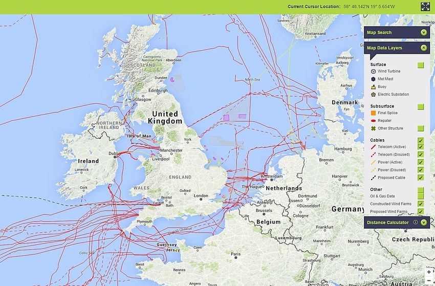
Expanding communication and ending isolation made sea divided regions to come into contact by
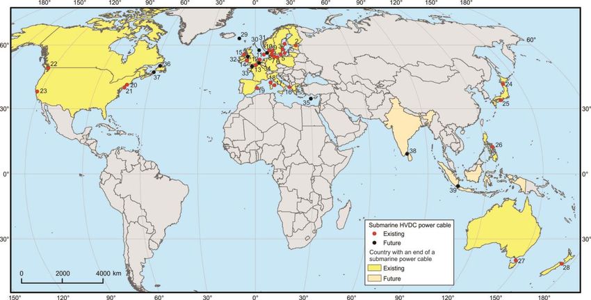
laying down cables to connect their communication and power networks. At the moment there are
almost 8000 km of HVDC submarine power cables in the world (Fig. 9) but the total length of
cables laid down on the seabed reaches a staggering number of 106 km, i.e. mainly communication
cables. However, with the continuous development at the present construction rate, submarine
cables will become an ubiquitous element in the power transmission landscape.
Existing HVDC submarine power cables 15. Moyle Future HVDC submarine power cables
1. Fenno-Skan 1 and 2 16. Italy-Greece 29. IceLink
2. Eastlink 1 and 2 17. SAPEI 30. MSNLink and NorthConnect
3. Gotland 1,2 and 3 18. SACOI 31. Nord.Link and NorGer
4. NordBalt 19. Cometa 32. UK Western Link
5. SwePol 20. Cross-Sound 33. IFA2
6. Baltic Cable 21. Neptune 34. NemoLink
7. Kontek Interconnection 22. Vancouver Island 35. Euro-Asia Interconnector
8. Storebælt 23. TransBay 36. Labrador-Island
9. Konti-Skan 1 and 2 24. Hokkaidō–Honshū 37. Maritime Link
10. Cross-Skagerrak 1, 2, 3 and 4 25. Kii Channel 38. India-Sri Lanka Interconnection
11. NorNed 26. Leyte-Luzon 39. Sumatra-Java
12. BritNed 27. BassLink
13. Cross-Channel 28. Inter-Island
14. East-West Interconnector
Fig. 9 – Submarine power cables in the world
More than 70% of the HVDC submarine cables in the world (both in terms of number and length)
are located in European adjacent seas (Fig. 10). Islands close to the shore and archipelago nations
are also places targeted by this technology. The vast majority of submarine power cables have a
17length of less than 300 km. They usually link countries separated by small to medium width water
bodies on the same continent or at its fringes. There are a small number of intercontinental links
like Spain-Morocco interconnection and the Red Sea Cable (Egypt-Jordan) but they are HVAC
interconnectors and run on short distances (up to 30 km).
Fig. 10 – Submarine power cables in Europe
The first commercial HVDC submarine cable was built and laid down in 1954 in Sweden by ABB
linking the island of Gotland with the mainland. Its voltage was 100 kV and the capacity 20 MW.
The length was 90 km. Since then the technology evolved towards higher capacity and voltage as
well as towards optimization of the flow control. A list with the main submarine power cables in the
world can be consulted in Annex 1.
3.2 Spatial context
3.2.1 Geological and path survey
Prior to any decision for laying down a cable on the seafloor (power or telecommunications) a
geological and path survey must be undertaken. This survey should offer a complete and complex
image of the bottom of the sea in terms of bathymetry (depth of the sea), depth gradient (slope
18and topographical accidents), nature of the seafloor (lithology), environment conditions
(temperature, salinity, pH and their variation) and dynamic processes that take places in the water
body (waves, sea currents, icebergs) or affect the seafloor (turbidity currents and sediment flows,
earthquakes, active faults, active submerged volcanoes, lava emergence). All these investigations
are performed and assessed by geophysicists, geologists, oceanographers by using dedicated
equipment. Since power submarine cables are big investments and long-lasting features a wrong
assessment of these conditions would lead to an improper design of the cable and hence its
malfunctioning or additional costs of maintenance.
3.2.2 Water depth and subsea bed topography
Most of the transmission power cables at the moment are laid in rather shallow waters, i.e. at less
than 500 m depth. Only three cables go beneath this depth: HVDC Italy-Greece (1000 m), Cometa
HVDC (1485 m) and SA.PE.I. (1650 m), which is the deepest in the world. The two deepest ones
were both produced by Prysmian and are of mass impregnated (MI) paper type.
The routes chosen for cable laying try to avoid deep trenches or steep slopes while maintaining the
shortest path possible. As most of the submarine power cables installed until now cross shallow
and flat-bottomed seas covered with thick Quaternary sediments (Baltic Sea, North Sea, Irish Sea,
English Channel, straits between islands of Japan, Philippines, US, Canada, Australia, New Zealand)
the depth of the water and slope haven’t been of a major concern. The threshold of 1000 m depth
has been exceeded only in the Mediterranean Sea.
In water environments special attention must be paid to hydrostatic pressure exerted by the water
column, which might become an important factor both in projecting the materials used and in
manoeuvring methods for laying or repairing the cable. The pressure increases steadily with depth
adding around one atmosphere (atm) at each 10 m depth (Table 2 and Fig. 11).
Although the cable sheath is built to resist to high mechanical stress and manoeuvres, special
attention is paid when manufacturing segments for deep waters. This is important during cable
installation when high tensile forces are applied to cables laid in deep waters.
As a recommended practice (DNV, 2012) the components in the cable cross section must be able to
withstand to a pressure not smaller than 3.5 MPa or the pressure corresponding to the maximum
water depth multiplied by a factor of 1.25. The casings for cable joints must be able to resist at
least to 3.5 MPa or to the pressure corresponding to the maximum water depth multiplied by a
factor of 1.5.
The latest generation of materials used for submarine power cables respond better to hydrostatic
pressure action. The problem is more stringent for older oil-filled insulation power cables, still in
19use but generally in shallow waters. The new generations of mass-impregnated paper or XPLE
insulations are made of high-density and high-viscosity compounds whose properties and function
are not pressure influenced.
Table 2 – Water column pressure at different depths
Depth (m) Pressure (atm) Pressure (MPa)
1 1.10 0.11
10 1.99 0.20
100 10.92 1.10
200 20.84 2.11
500 50.60 5.12
1000 100.20 10.15
1500 149.80 15.17
2000 199.40 20.20
3000 298.61 30.25
5000 497.02 50.36
Fig. 11 – Water column pressure variation with depth
10000 993.04 100.61
The power cables laid down until now cross continental seas (large bodies of salt water situated on
the continental shelf marginal to an ocean). The continental shelf is characterized by shallow
waters (up to 200 m, in some cases up to 400 m) dipping gently with an angle rarely steeper than
1° (0.1° in average) (Fig. 12).
Fig. 12 – The main components and major submarine landforms of a continental margin
There are no major or sharp geomorphological accidents or asperities. In most of the cases the sea
bottom is covered with a thick layer of Quaternary sediment which makes it rather flat. It is made
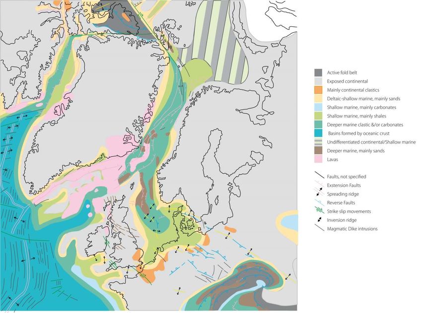
up of recent deposited particles: sand, silt, clay, gravel or of biological origin (Fig. 13). Sometimes
these can be loosely cemented which offers them a higher hardness. Most of the North Sea
20seabed, where a lot of submarine power cables are laid, has this composition. Due to the low depth
of the water which can make the cable subjected to actions from above (vessels’ manoeuvres,
anchoring, dragging) the cable is buried in a sediment layer of 0.3-1 m depth. This operation is
performed up to a depth of around 600 m.
Fig. 13 – The main geological formations in the North-East Atlantic (Norlex, 2008)
In some areas old and much harder rocks are exposed at the seabed surface. The methods used for
crossing these areas depend on the nature of the rocks and their arrangement. They can go from
cutting a trench of 0.5-0.7 m deep into the rock and bury the cable in it to laying the cable over the
rock and covering it with metallic mattresses.
The cables in the Mediterranean Sea dip beyond the continental shelf continuing on continental
slope reaching in some parts the continental rise and crossing canyons and seamounts as in the
case of the SA.PE.I. power cable (Fig. 14).
The continental slope increases the link between the continental shelf and the continental rise,
from approximately 200 to approximately 3000 m. Its slope averages 4° but this depends largely
on the local or regional geological setting. Pacific Ocean continental slopes are steep while the
Indian Ocean ones are the flattest. Although it dips at a rather small slope, local geological faults
21or tectonically active margins can cause steep drops, which can be even vertical. These slopes are
mostly covered by recent loose sediments but very often hard rock outcrops are present. In their
upper part the effect of streams from the continent is visible by the prolongation of valleys
forming submersed canyons.
Steeper slopes may determine a more accentuated rhythm of dynamic processes like submarine
landslides or turbidity flows which can impact on the cable most of the time with serious
consequences (Carter et al., 2014).
Fig. 14 – The bathymetric cross-section of the SAPEI power cable
Crossing these ups and downs would lengthen the cable, although by a small fraction. The depth
swing will also require the cable with an optimal structure, the best tradeoff between depth and
pressure related requirements, weigth and costs.
For long power cables crossing areas with great depths different materials in the cable’s cross
section were proposed for deeper and shallower segments. This is the case for NorNed in the North
Sea and SA.PE.I. in the Mediterranean. For the SA.PE.I. cable the deep sea segment required a
conductor made of aluminum while the shallow sea segment allowed for a copper conductor. The
reason for this lies mainly in reducing the weight while being able to maintain the tensile force
during installation but also in meeting the technical capabilities of the vessel used for this
operation. As it is costly and time-consuming to operate cables at great depths having a small
number of joints or even none would be advisable. That means longer one-piece segments or
22designing new cable structures in order to reduce the weight if the same vessels were to be used.
Alternatively new vessels with more carrying capacity would have to be built in order to
accommodate the longer segments.
With more ambitious plans in the Norwegian region and the Mediterranean Sea in the near future
more diverse geological settings should be met. The experience gathered from telecommunication
cables already laid in similar areas could be adapted and used to power cables.
3.2.3 Geological structure and lithology
As the submarine power cable is laid on the seafloor knowing the nature of the bedrock is of
critical importance. The lifetime of a cable is longer and its operation easier if the cable is laid in a
stable environment. The environment of the seafloor is very diverse due to its varied geology and
processes that affect it. It is also depth dependent with the more dynamic processes acting close to
the surface.
Seafloor geology can be as diverse as the nature of its structural setting (Fig. 15)
Fig. 15 – Seafloor spreading and the main geological structures
The major components of an ocean basin are:
the mid-ocean ridge – a continuous mountain chain built by rising magma;
the ocean floor – a vast expanse of older lava flows now solidified and covered by a thick
layer of sediment that takes the form of an abyssal plain crossed by ridges and trenches;
ocean trenches – deep trenches (≥ 5000 m depth) where two tectonic plates collide and
with one subduct under the other.
While most of the seafloor environment is rather stable with few dynamic processes, there are
places where changes take place at a higher rate. Mid-ocean ridges and ocean trenches are such
places. Along mid-ocean ridges lava rises at places at the surface rendering these areas
23impassable. The Mid-Atlantic ridge forms a continuous subsea mountain chain of more than 10000
km length. Submarine volcanoes pose the same problems although their lava flows are more
localized. Nevertheless the nearby accompanying phenomena (high water temperature, corrosive
substances) represent a major threat to submarine cables. However, as the location of the
volcanoes and lava eruption lines are well known this risk can be reduced by routing the path to
avoid these areas.
Other areas are affected by active faults which might not be expressed in seafloor morphology
since they might be covered by sediments but a sudden quake can cause landscape modifications
or trigger landslides.
Most of the seafloor is covered by a thick layer of sediment that averages 450 m in thickness (Fig.
16). It can be thinner on mid-ocean ridges where the bedrock formed by hard rock can be exposed,
sometimes even lava flows.
Fig. 16 – Total sediment thickness of the world’s oceans and marginal seas (Source: NOAA)
Although the predominant process under the water surface is sedimentation the water movement
can displace finer particles especially in the coastal areas causing the seafloor bathymetry to
change.
24Soft sediment (clay, mud, silt, sand) is easier to dig in to place a cable in a trench. However it is
also easier to get the cable removed or displaced by waves and currents, making it prone to
accidents. This threat is much reduced with increasing depth where the effect from waves and
currents becomes lower or negligible. Harder sediments like gravel offer a better protection since
they are heavier and less prone to displacement but more difficult to dig and hence resulting in
higher costs.
3.2.4 Geodynamic processes
On the continental slope, where the value of the slope gradient is higher, the accumulation of fine
loose sediments in large quantities might pose problems of slope stability. When this is combined
with a burden of coarser sediments arrived with the streams discharge from the continent, their
equilibrium might become instable. Water fills all spaces and pores in the sediment and can act as
a lubricant. An event like an earthquake can trigger the slide of the sediment mass, which more
often follows the path of the submarine canyons or other negative landforms. Sometimes, the own
weight of the sediment might grow beyond the stability threshold and the landslide doesn’t need
an initial shake in order to initiate.
Much information about the processes affecting submarine sediments was obtained from cables’
breaks (Carter et al., 2014). Since most of the submarine cables are telecommunication
connections the experience assembled comes from this field.
In areas close to the shore the main dynamic processes are determined by waves and sea currents
as well as sediment influx discharged by rivers. The magnitude of their actions depends on the
local topography of the coast, the depth of the water, the inland petrography and the climatic
pattern (rainfall, humidity, seasonal swing). In areas with high seasonal rainfall combined with
softer rocks (sand, soft sandstone, clay) erosion can be strong enough to grind up to 10000
tons/km2/year, which go into sea and build sediment deposits. This big quantity of material
transported over hundreds or thousands of years builds the largest sediment accumulations on
earth taking the form of submarine fans (Talling et al., 2013). Large accumulations of sediment
(>100 km3) can fail to remain still and start moving along the slope at high velocities (up to 19
m/s) reaching the deep ocean. Small volumes of sediment (0.008 km 3) found at canyon heads can
also start moving at high speed (5 m/s) for hundreds of kilometres (Carter et al., 2014). If power or
telecom cables are on their movement paths these swift displacements can break them or cover
them with sediment which can exert additional mechanical stress.
A key lesson learned from previous submarine telecom cables is that active submarine canyons,
fed by rivers with high discharge should be avoided. However this implies choosing an alternative
route, which might be longer and results in a higher cost. When this is not possible due to cost
25restraints another option would be to place the cable at greater depths in the canyon where the landslides and turbidity flows begin to decelerate and have a lesser damaging potential. Some cables are laid on a river bed before they enter the sea. A river bed may suffer important modifications in topography due to alternation of sedimentation periods with erosional ones. The difference in depth at the same place can be in some cases of a few meters. In order to secure the cable and avoid its exposure it must be buried at a higher depth than on the seafloor. For the NorNed HVDC cable laid in the Waddenzee area (North coast of The Netherlands), with a lot of moving clay sediment, a 3 to 5 m deep trench was dug in order to protect the cable against moving sediment (CEDA, 2005). Prior to cable laying, during path survey a multitude of geophysical investigations are performed in order to have a clear view on the seabed properties and stability. These investigations are performed with specialized tools, which measure the water and sediment depth. Water depth is measured by echo-sounding. This has evolved into multibeam systems (Carter et al., 2009), which offer an image over a wider swath, which can be as much as 20 km wide. The nature of the seabed and its structure is investigated by seismography. Waves at different wavelengths penetrate through water and seabed at variable depths according to their energy. The strength of the bounce sent back to the receiver gives data about the nature and depth of the reflection discontinuity. Sediment coring complements the image of the seabed and helps to assess its stability and suitability for cable burial. Another geo-dynamic process which might affect the cables is the sea-bottom scouring exerted by icebergs. These are big chunks of ice loose from the inland glaciers when they reach the sea. They are more common and larger in the waters surrounding Antarctica and Greenland but not limiting at that. Their size depends on the behaviour of the ice and its internal structure (cracks, plasticity, temperature, tensional forces). Although they usually might be just few meters (sometimes tens of meters) tall, most of the volume lies below the water surface. The biggest icebergs can reach more than 200 m deep below the sea surface. In their drift they can reach shallower waters and come in contact with the sea bottom where they can plough more than one meter into the bedrock posing threats to the submarine cables. As most of the icebergs originate from inland glaciers a special attention must be paid to areas where these enter the sea on their permanent routes. In a study mentioned by Burnett et al. (2013) most cable (telecom) damages in western Greenland coasts occurred in water depths less than 25 m from impacts with fixed and floating ice. These potential hazardous areas can be identified through a preliminary study and avoided by the cables by rerouting or applying special protection measures (deep burial, metallic cases). Deep reaching wandering icebergs can however always be a threat that is hard to overcome. 26
3.2.5 Sea currents, waves

The movement of water can affect the cable in many ways. The most important movements of the
sea water are represented by waves and currents. Waves are the result of wind blowing over a
body of water maintaining a constant direction for a period of time. The kinetic energy of the
moving air mass is transferred to the water surface forming undulations whose height and length
depend on the wind intensity and duration. Sea currents are horizontal flows of water through the
sea or ocean. They can be the result of predominantly blowing winds over large expanses of water
or part of the pattern redistributing the heat in oceans and seas.

Both types of movements can affect submarine cables by the sole strength of water action or by
redistributing the sediment. The depth of the waves and currents actions depends on the size
and/or speed of these dynamic elements of the sea. Higher waves make their action felt at higher
depths. Stronger and faster currents can displace and transport more sediment. The higher the
wave or faster the current the more power they have to move coarser particles from the seafloor.

The action of the waves is stronger on the shore or in shallow waters fading with increasing depth.
In general, the action of waves stops at around 30 m depth. Only exceptionally, during strong
storms the waves’ action is felt deeper. The coasts, especially the sandy ones suffer the most
dramatic changes from the waves’ action. When cables in such areas are not buried deeply enough
the removal of sediment may expose them to the surface (Fig. 17). In such cases a deeper trench
should be considered.

     Fig. 17 – Cable exposure due to waves’ action on a sandy beach in Great Britain (Source: aphotomarine.com)

In shallow rocky waters the waves’ action pose a threat for the cable if the cable is not well
anchored in case that a trench was not the option.

                                                                                                                  27
3.2.6 Temperature, salinity, corrosion
Sea water characteristics differ from place to place due to climatic zones, influences from inland
waters, biotic activity and depth. These characteristics orient the HVDC cable manufacturing
industry to using materials that have a neutral interaction with salt water.
Electric current running through a conductor causes its temperature to increase. If the current
becomes too high the conductor reaches a critical temperature at which parts of the insulation
cannot function properly or even start to melt. Under normal operating conditions the cable’s
temperature should not reach those critical limits. The environmental temperature also plays an
important role in keeping the functional parameters in their optimal range. As most cables are laid
in rather cold regions the lower temperature has a cooling effect on the cable improving its
efficiency.
Sea water temperature follows the general pattern of climatic zones with local influences caused
by landmasses (Fig. 18). As a general rule temperature drops with depth (Fig. 21) reaching 4 °C at
1000 m depth (Fig. 19) maintaining this temperature down to the sea bottom.
Fig. 18 – Annual temperature at the ocean’s surface (Source: NOAA)
28Fig. 19 – Annual temperature at 1000 m depth (Source: NOAA)
Salt water is a corrosive environment. Salt is present everywhere in the sea water in variable
concentrations. The average salinity in planetary ocean is 33-36‰ with large variations (Fig. 20).
Fig. 20 – Annual salinity at the ocean’s surface (Source: NOAA)
29In shallow and/or closed sea located between tropics (but not only) with strong evaporation the salinity can reach 37-40‰ as it is the case for the Red Sea, the Mediterranean Sea, the Arabian Sea or the tropical Atlantic and Pacific. A major tributary river can lower the salinity of a sea or part of it as it is the case for the Black Sea, the Baltic Sea, the North Sea, the South China Sea and the Golf of Bengal. Salinity is lower along the coasts and higher in the open sea. The North Sea has a salinity of 32-36‰ in the open sea and 15-25‰ close to the shore. Salinity is also a result of the global ocean circulation pattern which represents a complex movement driven by differences in water density and salinity and by heat accumulated and atmospheric influences (pressure, wind, temperature). Since salt has a greater specific weight than water, a higher salinity causes heavier water which dips at greater depth. Generally the salinity increases with depth (Fig. 22) but the continuous movement of water leads to mixing. Fig. 21 – Temperature decrease with depth (Source: dosit.org) Fig. 22 – Salinity increase with depth (Source: dosit.org) The cables must be protected against the corrosive effects of the salty water and this issue must be seriously tackled by the cable industry. The primary protective layer against the salty water is the armouring which is composed of zinc-coated steel wires (Worzyk, 2009). The zinc layer around steel wires is 50 µm thick. The secondary protective layer consists of a bitumen sheath, which might be eroded or removed during the installation process or afterwards. It is replaced lately by an insulation sheath of high density polyethylene. The zinc and steel remain as main barrier against the salty water. Their decay rates in natural submarine environments are 1-50 µm/year for zinc and 10 µm/year for steel. Burying the cable in the sediment reduces the amount of water in contact with the cable lowering the corrosion. Experience showed that aluminium must be avoided as component in the armouring. 30
As the cables are water proof and have a neutral interaction with salty water the natural salinity
found in planetary oceans doesn’t pose special problems (Carter et al., 2013).
3.3 Technology used and materials
3.3.1 HVDC cable
The submarine environment imposes some basic requirements to power cables that run through it
(Zaccone, 2009):
long continuous lengths
high level of reliability with practical absence of expected faults
good abrasion and corrosion resistance
mechanical resistance to withstand all laying and embedment stresses
minimized environmental impact
minimized water penetration in case of cable damage
There are many companies producing power cables in the world but just few of them have
experience in manufacturing submarine power cables for long distances and high capacity. ABB,
Alcatel, Prysmian and Nexans manufactured most of the existing submarine power cables in the
world. The latter two have also specialized vessels that allow them to install the cables at sea.
Prysmian is an Italy-based multinational company headquartered in Milan. Its main factory Arco
Felice is located in Naples, Italy. It holds also the “Giulio Verne” vessel, which was specially built and
equipped for laying power cables at sea.
Nexans is a French cable manufacture company headquartered in Paris. The submarine power
cable factory is located in Halden, Norway. Nexans lays down the cables at sea with its purpose-
built vessel Skagerrak.
If for an overhead HVDC power line a simple conductor is required, manufacturing a power cable
for submarine use implies meeting the technical requirements stated above. A train of processes
aimed at strengthen, insulate and protect the cable makes its manufacturing a high specialized skill
(Fig. 23).
31Fig. 23 – Sketch of the main processes for producing a power cable by Prysmian (Source: pesicc.org)
3.3.1.1 Cable arrangements
There are different possibilities to arrange the cables’ layout depending of the system
configuration (monopolar or bipolar):
Two separate single-core cables
Two single-core cables bundled
Single-core cable with metallic return
Two single-core cable with metallic return
Concentric cable
The two first layouts are used in bipolar system configurations while the last three in monopolar
configurations.
3.3.1.2 Voltage and capacity
Electricity transfer over long distances and for high power is made at high or very high voltages. By
increasing the voltage the losses become lower and the capacity of the line increases (see above).
Over the years the voltage has gradually increased from 100-250 kV for the first commercial
power cables in the ’50s-’70s to 300-400 kV ten years later. Most of the newer submarine power
cables in the world operate at 450-500 kV. Prysmian and Siemens are currently constructing the
32first submarine HVDC link with a voltage of 600 kV, i.e. the highest in the world between Wales and
Scotland (UK Western Link).
3.3.1.3 Joints
It is preferable that submarine power cables consist of a minimum number of segments, ideally
one. While for shorter cables this is possible, for longer ones more segments must be linked
together into a longer piece. The segments are connected by using joints which are pieces of
equipment that ensure the conductors, sheaths and armours on both parts are properly in contact
(Fig. 24).
Fig. 24 – Sketch of a cable joint (Source: campbellwhite.com)
Joints can be rigid or flexible depending on the local environmental conditions.
3.3.2 Cable structure, materials and properties
The structure of the cable must ensure a high efficiency in electrical transmission, a good
insulation and magnetic shielding along with a strong mechanical resistance. The structure may
differ in materials and layout depending on manufacturers and environmental conditions.
The cables’ structure includes a set of layers around the conductor – mainly copper to ensure the
physical insulation, impermeability, mechanical strength but also flexibility and electrical and
magnetic shielding.
HVDC submarine cables consist of one primary conductor by which the current is transmitted and a
return path represented by another conductor or via seawater using an anode/cathode. In HVAC
cables the current is transmitted using three conductors.
The conductors must be insulated against any external contact for the whole length of the cable.
There are three main solutions for insulation that are widely used:
Self-contained fluid-filled cables
SCFF/SCOF (self-contained fluid-filled / self-contained oil-filled)
33You can also read