Red Sea MAXC-Series ENG DE
←
→
Page content transcription
If your browser does not render page correctly, please read the page content below
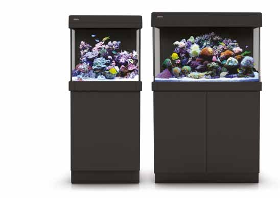
Plug & Play®
Aquarium

Red Sea MAX® C-Series
               Complete Coral Reef Systems

          Installation and Operation Manual

                     ENG    DE   FR
ENG 2-24 DE 28-51 FR 54-77
ENG

Red Sea MAX® C-Series
   Complete Coral Reef Systems

 Installation and Operation Manual
Red Sea MAX C-Series

    MAX® C Installation & Operation Manual

    Safety......................................................................4
    Location...................................................................5
    Unpacking the MAX®C System................................6
    Components............................................................7
    Assembly.................................................................8
    Installation of Sump Components.................................10
    Installation of optional Chiller................................15
    Installation of Lighting Hood..........................................16
    Operation of Power Center.....................................18
    Initial Fill..................................................................18
    Operation of the Protein Skimmer.........................19
    General Aquarium Maintenance.............................20
    Trouble shooting.....................................................22
    Warranty..................................................................24

2
ENG
Congratulations on your purchase of the
Red Sea MAX® C-Series complete reef
system.
Red Sea developed the MAX® to provide a complete reef spec system
so that from the beginning, you can focus on the aquarium's inhabitants
rather than the hardware.
The Red Sea MAX® approach to the coral reef experience is to create
an environment that is specifically attuned to the needs of coral and
all reef inhabitants on an artificial reef. In the ocean coral reefs flourish
only where specific physical conditions prevail, such as sufficient light,
adequate current, stable temperature and water quality.
The Red Sea MAX® system provides the conditions that enable you to keep
a thriving, healthy reef in your own home.
This manual contains the installation and operational instructions for all of
the MAX® C-Series aquariums.
We hope that you enjoy your MAX® and wish you happy reefing.
To benefit from product update information and exclusive special offers to
registered MAX® owners, please register your MAX® on-line at redseafish.com
3Red Sea MAX C-Series
1 Safety
Please read and follow all safety instructions. d. To avoid injury, do not contact moving parts.
e. Always unplug an appliance from an outlet when not in use, before
DANGER: To avoid possible electric shock, special care should be
putting on or taking off parts, and before cleaning. Never pull the cord
taken when handling a wet aquarium. For each of the
itself to remove the plug from the outlet. Grasp the plug and pull to
following situations, do not attempt repairs yourself; return
disconnect.
the appliance to an authorized service facility for service or
f. Do not use an appliance for anything other than its intended use.
discard the appliance.
The use of attachments not recommended or sold by the appliance
manufacturer may cause an unsafe condition.
WARNING: To guard against injury, basic safety precautions should be
g. Do not install or store the appliance where it will be exposed to the
observed, including the following:
weather or to temperatures below freezing point.
a. Do not operate any appliance if it has a damaged cord or plug, if it is h. Make sure an appliance mounted on a tank is securely installed before
malfunctioning, or if it is dropped or damaged in any manner. operating it.
If the external cable is damaged, it shall only be replaced by the
Read and observe all the important notices on the appliance.
manufacturer.
b. To avoid the possibility of the appliance plug or receptacle getting NOTE: A cord rated for less amperes or watts than the appliance rating
wet, position the aquarium stand and tank to one side of a wall may overheat. Care should be taken to arrange the cord so that
mounted receptacle to prevent water from dripping onto the it cannot be tripped over or pulled accidentally.
receptacle or plug. You should create a "drip loop" (Figure 1) for each
cord connecting an aquarium appliance to a receptacle. The "drip
loop" is that part of the cord below the level of the receptacle, or
the connector. Use an extension cord, if necessary, to prevent water
traveling along the cord and coming into contact with the receptacle.
If the plug or receptacle does get wet, DO NOT unplug the cord.
Disconnect the fuse or circuit breaker that supplies power to the
appliance. Then unplug the device and examine for presence of water
in the receptacle.
c. Close supervision is necessary when any appliance is used by or near
children. Drip Loop
figure 1
4ENG
2 Location
The first step in setting up the MAX® C is to choose a suitable location. Accessibility
• Back: Ensure that there is at least 10cm (4") of clearance behind the
Electric Supply MAX® to allow for sufficient air circulation for a chiller and general ease
of operation.
Ensure that the electric power supply outlet used for the MAX® C is
correctly rated for the system (C-130 325W / C-250 500W), plus • Sides (Rear): Ensure that there is sufficient room (approximately
whatever additional equipment (such as a chiller) you plan on 60cm/24”) between both sides of the aquarium and any adjacent walls
adding. The power supply outlet must be grounded and connected to or furniture for access to the rear of the tank. This is required for the
a circuit protected by a RCD/RCCB (residual current device or residual regular maintenance of the surface skimmer, protein skimmer, flow
current circuit breaker) also known as a GFI/GFCI (ground fault circuit pumps and filter media as well as installing/removing cables to power
interrupter). center.
• Sides (Front): Ensure that there is approximately the length of the
Floor tank free on at least one of the sides. This is to enable the installation/
replacement of the color trim on the tank.
The floor directly below the legs must be level and rated for a static
loading of at least 30kg/cm2 (425 lbs/square inch).
General considerations
Room temperature Ensure that the area surrounding the aquarium is waterproof and
consider moving away anything that water might damage or which may
Site selection is important for correct temperature maintenance.
be corroded by salt.
We recommend that you keep the ambient room temperature a
comfortable and stable 22°C / 72°F. Avoid placing the tank in front of
an air conditioner, heating vents or direct sunlight. A well ventilated
room with moderate light is the best place to position the aquarium.
5Red Sea MAX C-Series
3 Unpacking the MAX® C System
Please read this section carefully before proceeding.
NOTE: Every precaution has been taken to ensure the safe arrival of the
1. Remove the protective packaging from around the hood. MAX® C aquarium system, however before installing a new glass
aquarium it is advisable to inspect it for damage or leaks.
2. Remove the hinge pins from either side of the central opening in the
hood and set aside for later assembly.
Place the aquarium in a suitable location and fill the tank and
3. Placing one hand under the hood from the center opening at the rear,
rear sump to approximately 2.5cm (1”) below the top of the
carefully lift the hood out of the box and place on a flat surface.
glass. Leave the water standing for 15 minutes and inspect for
4. Remove the light tubes, components and any packaging materials
leaks.
that are packed inside the aquarium.
5. Open the accessory box and remove all of the parts for later Syphon all of the water out before moving.
assembly.
Removing the aquarium
CAUTION: The aquarium has a bare glass bottom. Before removing the
aquarium from the box prepare a smooth, soft, clean flat
surface that can hold its weight.
With one person positioned at either side of the box, grasp the upper
rim of the aquarium and gently lift it out and place on the designated
surface.
Remove the Cabinet top board from the bottom of the aquarium.
Approximate weights of Aquarium (empty)
Model Metric (kg) Imperial (lb)
C-130 25 55
C-250 40 90
6ENG
4 Components
MAX® C system main components C-130 C-250
MAX® C type glass aquarium with integral rear sump 130L 250L
MAX® C Cabinet Self-assembly Self-assembly
Power Center Cabinet Unit Cabinet Unit
MAX® C T5 closed top lighting hood with timer 2 x 55W 6 x 39W
Color trim pack for aquarium Type-C Type-C
MSK Protein Skimmer MSK600 MSK900
Circulation pumps 1 x 1550lph 2 x 2150lph
Heater 150W 150W
Media Rack 4 shelf 4 shelf
Filter sponges 1 2
Carbon media 1 bag 2 bags
Water Cooling Fan Dual Fan Dual Fan
Accessory/Chiller Kit. Type-C Type-C
7Red Sea MAX C-Series
5 Assembly
Perform the assembly and installation of all of the components in the PTO. The door should spring open. If the door does not spring open
order described below before adding the water to the system. adjust the position of the PTO by rotating the front end of the shaft
anticlockwise half a turn. Repeat this adjustment until pressing the door
NOTE: Left and Right designations in this manual are when looking causes the PTO to operate.
from the front of the Aquarium.
After assembly, place the cabinet in the desired location.
5.1 Cabinet assembly 5.2 Cabinet mounted Power Center
WARNING: If you are not experienced in the construction of self Remove the Splash Cover from the Power Center by sliding it towards the
assembly furniture, seek suitably qualified assistance. front.
Align the mounting holes on the base of the Power Center with the
Detailed instructions for the assembly of the MAX® C cabinet can be found threaded plastic inserts on the internal wall of the cabinet.
in the accompanying graphic manual.
Use the 4 long M4 screws and 1 short M4 screw as indicated to attach the
The assembly of the cabinet requires the use of a regular crosshead Power Center to the wall. Do not over-tighten the screws.
screwdriver. Do not use an electric screwdriver.
Pass the main cable through the hole in the rear of the cabinet and check
Hardware for the assembly of the cabinet may be found in the Accessory that it is able to reach the electric wall outlet. Do not plug the power
Parts box packed inside the aquarium. center into the wall outlet until instructed at the appropriate time in the
assembly process. Check that
Adjustment of the Push-To-Open (PTO) all of the switches are in the
door opening unit. “off” position.
Pressing the end of the PTO unit by 1.5mm (1/16”) will spring the shaft Stick the socket identification
forward by 5cm (2”) to the open position. label (showing the connection
Pushing the PTO shaft back inside the cabinet will lock it in the closed between sockets and switches)
position. inside the cabinet, above the
power center.
After assembling the cabinet door, make sure that the PTO is in the
closed position and allow the soft close hinges to fully close the door.
With the door in the closed position press the door in the region of the
Cabinet mounted Power Center
8ENG
5.3 Cable Channels 5.5 Color Trim
Attach the 2 cable channels to the rear wall The color trim pack contains a set of plastic parts for the upper and lower
of the aquarium. rim of the aquarium that are painted to the designated color.
The color trim for the upper and lower trim are fitted by sliding them on
5.4 Placing Aquarium to their corresponding black rim that is located along top and bottom
edges of the aquarium.
Lifting the glass aquarium onto the cabinet
will require at least 2 people. The top of the
Cable Channels
cabinet is approximately 85cm (33”) from
the floor. Ensure that anyone lifting the aquarium is physically suitable
for such an operation and has been instructed in the correct methods of 2 3 4
1
lifting heavy objects.
Aquarium must be lifted from the bottom.
Take care not to damage the plastic rim on the front and sides at the
top and bottom of the glass. Slight damage to the rim will not affect the
First assemble the top and bottom sides by sliding in from the front and
assembling of the external color trim.
initially push them until they protrude about 75mm (3”) out the back
Before lifting aquarium, place the assembled cabinet in the final side of the aquarium. Note that the corner connector on the side sections
operating position (see location above) and set the glass aquarium in should be facing the front.
position on top.
Slide the top and bottom front sections and assemble the corners on the
The back of the glass should be flush with the rear edge of the cabinet corner connectors. Adjust the trim so that the small gap between the trim
top board. The front and sides of the glass should protrude slightly and the corner is even on both sides.
beyond the edges of the cabinet board such that the protrusion is
Slide the side sections forward into the correct position.
approximately even on both sides. Incorrect positioning of the aquarium
on the cabinet will interfere with the assembly of the color trim. Insert the rear trim covers into the back of the side sections.
Once the aquarium is correctly aligned with the cabinet, check that the
cabinet has not moved. If necessary readjust the position of the cabinet.
9Red Sea MAX C-Series
6 Installation of Sump Components
The MAX® C-Series aquariums are divided into 2 parts, Aquarium and the Rear Sump that houses all of the filtration and circulation systems.
1. Detachable Surface Skimmer
2. Protein Skimmer 9
10
3. Media Rack
4. Carbon 1
5. Circulation Pump
6. Pump Outlet Nozzle
7. Filter Sponge 6
8. Heater
9. Water Cooling Fan
10. Accessory Pipe Unit 8 2
11. Chiller Pump (not supplied) 3
7
11
4
5
C-130 sump component assembly diagram
shows position of optional chiller pump and piping
10ENG
10 9
1
6 6
8
2
3
7 4 7
4
11
5 5
C-250 sump component assembly diagram
shows position of optional chiller pump and piping
11Red Sea MAX C-Series
Overview of the MAX® C rear sump filtration and Water loss due to evaporation will cause a drop in the water level of the
circulation system rear sump which can be monitored through the viewing slot at the top
of the side panels on both sides. In order to achieve the optimal filtration
The water flows from the aquarium to the rear sump via a detachable performances, the water level inside the filtration chamber should be
surface skimmer located across the top of the dividing glass wall that kept at the optimum levels.
directs the organics laden water from the upper surface of the tank into
the sump. The circulation pumps located at the bottom of the sump NOTE: Before connecting any components to the Power Center ensure
return the filtered water back to the tank through multidirectional outlet that all of the power switches are in the “off” position
nozzles.
The MAX® C-Series sumps contain multistage filtration consisting of a 6.1 Protein Skimmer:
reef-spec protein skimmer, activated carbon and mechanical filtration
materials. The sump has dedicated space available for additional The MSK protein skimmers consist of
chemical filter media as well as the addition of an optional chiller pump. three parts: skimmer body, collection
cup and skimmer pump.
Water circulation is set at 10 to 15 times the entire water volume per
hour with forced flow through the mechanical and chemical filter media Familiarize yourself with the
while the protein skimmer treats the water at the SPS spec of at least 3 skimmer pump by disassembling and
times per hour. reassembling all of the component
parts. Ensure that the impeller a
The performance of the filtration system is directly related to the water
chamber cover is correctly positioned
level inside the aquarium and the rear sump however the MAX® C-Series
and properly secured by the bayonet
sump and skimmer design allows for the fluctuations in water height due
ring. Before use check that the pump
to the daily evaporation of water from the system.
and power cable are not damaged.
When all pumps are running, the water in the aquarium will be
maintained just below the bracing bars but above the external trim so
the water line in the aquarium will never be visible from the outside. Diagram key : b
The water level in the rear should be maintained at least 40mm (1½”) a. skim adjuster
below the water level in the aquarium to ensure a positive surface b. venturi inlet
skimming action at all times. c. air pipe
d. small air pipe
MSK 600 skimmer
12ENG
Assemble the skimmer as shown in the diagram.
6.2 Surface Skimmer:
1. Set the skim adjuster to its lowest position.
The comb sections of the surface
2. Connect the air pipe from the venturi inlet of the skimmer pump to
skimmer are easily removed for
the outlet of the silencer.
regular cleaning. Put your hand over
3. Connect the small air pipe on the inlet of the silencer. the surface skimmer. Hold the comb
4. An optional air valve is provided for use with the skimmer. Initially do (not the frame) between thumb and
not attach the air valve; it is only to be used if required as described fingers and pull upwards.
in the operation instructions (chapter 11; page 19).
5. Slide the skimmer into the skimmer compartment. Note the position
of the skimmer guides located on the inner wall of the rear sump.
6.3 Media Rack: Surface Skimmer / comb
6. Feed the power The media rack is supplied pre-
cable out of the assembled and placed in its normal
opening in the operating position within the media
d compartment of the rear sump.
right hinge bracket
above the rear Familiarize yourself with the media
wall, thread the rack by removing and reinserting it to
c
cable through the the media compartment.
cable channel and
plug the power 6.4 Carbon:
cable into the
Wash the carbon filter material
designated socket
under running water several times
on the power
to remove residual dust. It is
center.
recommended to soak it in water for
7. Remove the
24-72 hr. before usage otherwise
collection cup
during the first 3 days after set-up the Media Rack
from the skimmer
carbon may float and release micro air
body until after
bubbles from inside its pores.
assembling the
hood on the Place the washed carbon onto the designated shelves on the media rack.
aquarium. MSK 600 skimmer Ensure that the bag does not protrude outside the frame of the rack.
13Red Sea MAX C-Series
6.5 Circulation Pumps:
Familiarize yourself with the multidirectional 4. Screw the outlet onto the threaded connector and tighten against the
outlet by disassembling and reassembling it a glass. Initially adjust the nozzle to the downward position.
few times. 5. Feed the power cable out
When dry the nozzle does not rotate freely in of the opening in the hinge
the socket. Once assembled in the aquarium it bracket above the rear wall,
will move as required and will remain in the thread the cable through
desired position. the cable channel and plug
the power cable into the
Familiarize yourself with the circulation pump designated socket on the
by disassembling and reassembling all of the power center.
component parts. Ensure that the impeller
6. With the circulation pump
chamber cover is correctly positioned and
secured in position, push
properly secured by the bayonet ring. Screw
the black filter sponge into
the hose barb provided into the outlet of the
the pump chamber so that
pump.
the slit in the sponge is in
1. Before use, check that the pump and power cable are not damaged. line with the flexible pipe,
2. Assemble the flexible pipe to as shown in the complete
the pump so that the threaded sump assembly diagram.
connector for the outlet nozzle
is perpendicular to the pump as
6.6 Heater:
shown in the drawing.
3. Ensure that the rubber washer Inspect the heater for damage or cracks.
is in place on the connector, Set the thermostat to 26°C (78.8°F), insert the heater into the rear sump
lower the complete assembly in the position shown in the diagrams above and attach securely to the
into the pump chamber so that wall using the suction cup provided.
the threaded connector goes Place the heater cord over the back wall of the sump, thread through the
through the hole provided in cable channel and plug the power cable into the designated socket on
the glass wall. the power center.
14ENG
6.7 Water Cooling Fan Unit: 7 Installation of optional Chiller
The water cooling fan will be most effective to maintain the correct
temperature for a reef aquarium by evaporative cooling if the ambient
(not provided):
temperature around the aquarium is between 23-25°C / 73-77°F. For the long-term safety and vitality of reef inhabitants Red Sea
recommends the use of chillers with all reef aquariums. Both the
Place the water cooling fan unit on the rear wall of the sump close to the
aquarium and cabinet of the MAX® C systems are provided “Chiller Ready”.
right hinge bracket and tighten the screw so that the fan unit is secured
in position, do not over tighten. The 12Vdc power cable (part of the The MAX® C cabinet has air ventilation openings both at the front and
MAX® C lighting hood) should be connected to the socket on the back side rear to providing the free convection cooling necessary for the efficient
of the fan unit. Once connected the water cooling can be turned on and operation of aquarium chillers.
off as required by a switch located in the timer compartment of the hood. Use the Accessory/chiller kit to connect a pump and return pipes to a
chiller.
1. Attach approximately 30cm (4”) of 17mm (3/4”) flexible pipe to
NOTE: Evaporative water cooling by the use of fans such as the unit
the outlet of a submersible pump (the MAX® C circulation pumps are
provided with the MAX® C will increase the rate of evaporation.
suitable for this application) and attach one of the hose barbs to the
When using the water cooling fan monitor the water
free end of the pipe such that the hose barb is perpendicular to the
temperature and the water level in the rear sump.
pump.
2. Lower the pump and tube assembly into the sump so that the hose
barb is facing the rear of the sump. Feed the power cable out of
the opening in the hinge bracket above the rear wall, thread the
cable through the cable channel and plug the power cable into the
designated socket on the power center.
3. Connect the required length of 17mm (¾”) flexible tubing to connect
the inlet and outlet ports of the chiller to the hose barbs on the back
of the accessory pipe unit. Lock the tubes to the hose barbs with the
lock nuts.
15Red Sea MAX C-Series
4. Insert the accessory pipe unit into the window in the hinge bracket
and click it into position. Make sure that pump cables are positioned
8 Installation of Lighting Hood
in the recess provided on the sides of the pipe unit. Using the protective packaging from the top of the box as a cushion,
5. Push the hose barb of the pump into one of the connectors and screw place the hood upside down on a level surface.
the lock nut to hold it in position. 1. Remove the plastic screws from the transparent lens and open the
6. Connect the required length of 17mm (¾”) flexible pipe to the other light tube compartment.
hose barb. Insert the free end of this pipe into the sump as shown 2. Insert all of the light tubes, rotating them through 90 degrees until
and connect the bayonet to the other connector on the pipe unit. they are seated correctly in the lamp holders.
7. When first operating the chiller pump, check that the water is 3. Replace the lens, ensuring that the gasket around its inner edge is
circulating through the chiller without leaks at any of the connections properly positioned and secure in place with the plastic lens screws
in the piping. cover. Remove the protective film from the lens.
8. If connecting the chiller to an operating system pay attention to the 4. The hood is now ready to be placed on the aquarium.
drop in water level and refill the tank with freshly mixed salt water at
the same salinity, pH and temp. NOTE: After initial assembly, replacing the light tubes can be performed
with the hood attached to the aquarium
5. Check that the hood support is set in position as shown in the
diagram.
6. Feed both the hood power cable and the fan cable out of the opening
in the right hinge bracket and place
the hood on top of the aquarium.
Hood supports Skimmer - flap open
16ENG
7. Make sure that the hood fits securely around the rim of the tank; it supports together and position the hole at the top of the upper arm
may be necessary to adjust the position of the hood support to do in the recess provided in the hood. Insert the upper support pin to
this. connect the support to the hood. If you experience difficulty, check
8. Place the timer cover onto the hood. the alignment of the pins with the hole and try again.
9. Hold the skimmer cover in the "open" position over the skimmer 4. Lower the hood until the lower support arm is resting on the glass.
chamber, lining up its hinge holes with those of the hood. This intermediate position provides good access to most of the
10. Insert the hood pins (that were removed for unpacking), attaching aquarium with the light mainly directed across the water surface.
both the skimmer panel, timer panel and hood to the hinge brackets. 5. To obtain full access to the aquarium raise the hood to the full extent
Both panels should open and close easily with the pins securing the of the hood support arms. Push the lower join of the arms towards
hinge. the hood and gently lower the hood until it is supported in an almost
11. Thread the hood power cable through the cable channel and plug the upright position (figure c). It is advisable to make sure that the lights
power cable into the designated socket on the power center. are switched off before raising the hood to the full open position.
12. Plug the fan cable into the receptacle on the water cooling fan. 6. To close the hood first lower the hood to the intermediate position,
then unlock the middle and upper support arms and gently lower the
13. Raise the skimmer panel to the upright position and reassemble the
hood to rest on the color trim.
skimmer collection cup on the skimmer body.
Securing the hood and switching between the 3 NOTE: To disassemble the hood from the aquarium, raise the hood to
opening positions the intermediate position remove the upper hood support pin by
inserting the end of a small flathead screwdriver into the small
a b c recess in the head of the pin. Thereafter, remove the hood pins
from the hood hinges at the back.
DO NOT attempt to remove the hood support by prizing open the
support joint.
1. Make sure you have the upper hood support pin at the ready and fold
back the front section of the hood so that it lays on the main body
(figure a). When removing the hood from the aquarium make sure that the
power cable or fan cable do not fall in the water.
2. With one hand, raise the hood approximately to a 30° angle and hold
it open in this position (figure b).
3. With your free hand, snap the upper and middle arms of the hood
17Red Sea MAX C-Series
Lighting and Fan control 9 Operation of Power Center
The timer has a 3-position switch:
With all of the electrical components now installed and plugged into the
“I” (ON position) – daylights on, moonlights off Power Center, slide the Splash cover along the length of the sockets,
“O” (OFF position – daylights off, moonlights on allowing the recess in the bottom of the cover to collect the cables and
moving them towards the back of the cabinet. With the splash cover in
Clock symbol – automatically changes between the “I” and “O” settings
position, ensure that the individual switches are in the off position and
according to the timer setting.
plug the Power Center to the wall outlet.
Each black segment switch around the face of the timer represents ¼ of
The Power Center is protected by a resettable circuit breaker which
an hour (15 minutes). Move the segment switches to the outer position
will switch off the power to the complete power center in the event of
for the time period you want the daylights to be on. Move the segment
a short circuit in one of the components. In the event that the circuit
switches to the inner position for the time period you want the daylights
breaker is activated, locate the faulty item, disconnect it from the power
to be off.
center and depress the circuit breaker reset switch.
Rear switch (next to the timer) turns off the moonlights in the event that
you do not want them on automatically when the daylights are off.
Front switch (next to the timer) on/off for the water cooling fan unit. 10 Initial Fill
Set the actual time by rotating the dial until the arrow is pointing to the
Follow the mixing instructions for mixing your artificial sea water. It is
current time. This should only be done after the hood has been switched
advisable to place any substrate or live rocks in the tank before adding
on at the Power Center.
the water as this will significantly affect the overall volume of water
required.
Maximum
Optimum
Minimum
18ENG
Add the seawater to the main tank, rear sump and directly into the gradually raise the Skim Adjuster until the desired foam consistency is
skimmer (to prevent it floating instead of filling with water) until the achieved. If the foam is too wet, lower the Skim Adjuster.
water is at the level of the circulation pump outlet nozzles. Turn on the
skimmer pump, circulation pump/s and chiller pump if installed and add Over-Skimming
more water to the system until the water level in the rear sump is at the An uncontrollable flow of aerated water into the collection cup.
optimum water level as indicated by the bar across the viewing slot in
the side panel. In the event of over-skimming the excess water will flow back into the
sump from the overflow slot located at the top of the collection cup.
NOTE: If you have mixed your saltwater for the initial fill inside the
To control the over-skimming make sure that the Skim Adjuster is set in
aquarium wait until the salt is fully dissolved and that the water
its lowest position, add the air valve to the top of the air inlet pipe and
has reached the desired salinity and temperature before trying
reduce the air intake until the foam stabilizes. Continue controlling the
to set the final water level.
skimmer by adjusting the air intake. When the skimmer is stable with the
air valve fully open, remove the valve and control the skimmer with the
Skim Adjuster.
11 Operation of the Protein
Skimmer New Skimmers or Set-ups
Adjustment of the skimmer will be necessary from time to time due to Skimmers only produce foam if the water contains the proteins that
the constant changes in density and organic material in the water. bind to the surface of the air bubbles and give the bubbles the structural
rigidity they need to ascend the neck of the skimmer and settle in the
The function of the skimmer will not be affected by the normal
collection cup. In a new aquarium
fluctuation of the water level in the rear sump (due to evaporation)
set-up the bio-load is low and the
however the water level must be maintained between the maximum
amount of proteins is negligible.
and minimum levels shown.
New skimmers sometimes need
The consistency of the foam produced by the MSK protein skimmers is
a short break-in period of a
controlled by raising and lowering the Skim Adjuster.
few days before they begin to
The foam will be formed in the upper part of the skimmer body and function efficiently. Over-skimming
will build and climb up the neck of the collection cup. Set the position is common while harmless
of the Skim Adjuster so that the water level in the skimmer body is chemical residues that affect the
approximately at the base of the neck. surface tension of the water are
If the foam is too dry or it starts to accumulate lower in the neck, neutralized.
19Red Sea MAX C-Series
Feeding and Supplementing 12 General Aquarium
Skimmers are very susceptible to the effect of surface active compounds
such as foods and supplements that are added regularly to the aquarium.
Maintenance
Such materials can significantly affect the foam production and in some The long-term success and health of the inhabitants of your MAX®
cases cause over-skimming. Immediately before adding such materials aquarium depends on you. Proper planning makes reef care easier to
switch the skimmer off and leave off for 30 minutes or however long it manage and quicker to perform. This will leave you more time for the
takes until the skimmer will return to its normal foaming action without real goal: enjoying your aquarium. Care of the tank should follow a
repositioning the Skim Adjuster. regular, logical pattern. Divide the tasks into daily, weekly and monthly
procedures, including equipment checks, feeding, water parameter
Collection Cup testing and adjustments.
Monitor the amount of skimmate that accumulates in the collection cup You may find it helpful to make a systematic checklist of care activities
and empty the cup on a regular basis. When emptying the cup, clean the and keep a log of the activities performed. Your log does not need to be
inside of the neck by rinsing it with water, as the build-up of skimmate in complicated; you will need to track the following:
the neck will adversely affect the skimmer performance. If you wash the • The tank’s parameters – pH, salinity, temperature, etc.
cup with detergent make sure to rinse it thoroughly before returning it to • The general appearance of the tank and individual species.
the skimmer. • Equipment changes – when you changed light tubes or replaced
heaters, etc.
• Replacement of carbon or other filter media.
• Information specific to each animal – when they were added, moved
or removed, their approximate size, any signs of stress or ill health etc.
Water levels
Check the water level in the rear chamber on a daily basis and add fresh
water as required to compensate for any evaporation. Do not allow the
water level in the sump to remain outside of the min/max water levels.
If the water in the aquarium is too high check that the combs of the
surface skimmer are not blocked.
20ENG
Surface Skimmer To clean the pumps:
Remove and clean the combs of the surface skimmer at least once a • Unplug the power cord of the pump from the electric supply and
week to allow proper water flow and stable water level differentiation remove it from the aquarium.
between the aquarium and the rear sump. Periodically soak the combs • Remove the impeller housing and take out the impeller.
in a weak acidic solution (vinegar, citric acid) until any calcium carbonate • Clean all of the parts, impeller housing, impeller and the impeller
deposits have dissolved. chamber of the motor by wiping with a soft cloth or brush. To remove
calcium carbonate deposits soak the parts in a weak acidic solution
Protein skimmer (vinegar, citric acid) until deposits have dissolved.
Check the foam production in the collection cup and reposition the Skim • Rinse all parts thoroughly, reassemble the pump, ensuring that all
Adjuster or air flow as required to maintain a stable dry foam. Empty and pipes are connected securely and return to the aquarium before
clean the neck of the collection cup as required. reconnecting the power cable to the electric supply.
Pumps NOTE: If the pump makes mechanical noise after cleaning, replace
the impeller. The impeller is a wear item and may need to be
Checking that the circulation pumps are working well and are pointed in
replaced periodically.
the right directions. If you notice any regression in currents, check each
pump and the outlet nozzles for any obstructions (snails, crabs, carbon
chips, etc.). Water temperature control
To ensure proper function of skimmer and circulation pumps they should For optimum conditions a reef aquarium should be maintained at a stable
be cleaned on a regular basis. water temperature in the range of 24-28°C / 76-82°F (the stability of
the temperature being more important than the exact value). Slightly
NOTE: Aquariums with higher levels of Calcium and Alkalinity will higher temperatures can be tolerated for short periods of time as long
require more frequent maintenance. as the change in temperature is steady and not sudden. Monitor the
temperature at least twice a day, looking for dramatic fluctuations.
Avoid temperature differences of more than 2°C / 7°F during the day.
During season changes and when heating or cooling the house, monitor
the tank temperature more frequently, adjusting the heater/chiller as
necessary.
21Red Sea MAX C-Series
Change the carbon filter 13 Trouble shooting
Replace the active carbon filter every two months.
Q. My set up is new and the skimmer doesn’t seem to be skimming.
Lighting tube replacement A. Check that the salinity of the water is within the correct range for
Over 6-12 months, the intensity of the fluorescent tubes will decrease as reef aquariums. If the setup is new or if you have just cleaned your
much as 50% and the spectrum will narrow towards the red end, which skimmer, rinse thoroughly with water and return to the sump. The
can promote algae bloom. skimmer should start foaming within a few days. Skimmers react to
Refer to the installation instructions (chapter 8; page 16) for inserting changes in water density and other harmless chemical residue from
replacement tubes. Always switch off the complete lighting controller at the production process. While this is safe for your aquarium, it will
the Power Center before doing any maintenance work on the lights. impede the skimmer’s efficiency for a couple of days. Remember that
your skimmer will work only if the water contains proteins, as these
Lighting Compartment Lens proteins bind to the surface of the air bubbles and give the bubbles
the structural rigidity they need to ascend the neck of the skimmer
Wipe the lens regularly with a soft cloth. and settle in the collection cup.
Hood Fans Q. My skimmer is new and is producing a lot of weak, watery foam
Ensure that the air vents on either side of the hood are clean and free (over-skimming).
from dust. The cooling fans inside the hood are a wear item and may A. Production of an excessive amount of weak, watery foam – also
need replacing from time to time. Mechanical noise from the fans is an referred to as over-skimming indicates the presence of chemical
indication that they need replacing. substances that need to be removed by the skimmer. Lower the
position of the Skim Adjuster as necessary to reduce the water level in
the skimmer neck and if necessary reduce the air flow by adding the
air valve to the air inlet and restrict the air flow until you get a stable
foam production. It may take a few days for the skimmer to remove
all of the chemicals.
22ENG
Q. My set up is not new and skimmer isn’t producing foam or it is too super-saturating the water with air, i.e. dissolving more gas into
dry and builds on the neck. the water than is normal for the given temperature and pressure.
A. During a new set-up the bio-load is low and the amount of organics Once the super-saturated water leaves the skimmer, it “relaxes”
is negligible. If your MAX® is fully stocked, increase the height of the and releases the extra gas in the form of micro-bubbles. In the
skimmer shutter as necessary and open the air valve. Check the water MAX® C-Series the pumps are located near the bottom of the
level in the rear filtration chamber and raise it to the optimal line. If sump and are pre-filtered by a sponge that should prevent any
you still get light foam production inspect for blockage in the airline or air bubbles from reaching the pump inlet. There may be a buildup
skimmer inlet. of air trapped inside the sponge. Remove the sponge, rinse and
return it to the sump. You might be getting micro-bubbles if you
Q. My skimmer is not new and is over-skimming after feeding and/or are using tap water with water conditioners or natural seawater.
supplementing. Many conditioners, some synthetic salt formulae and impurities
found in natural seawater increase the surface tension of the water
A. See Feeding and Supplementing in chapter 11 (page19).
and cause a small proportion of the bubbles to escape out of the
skimmer chamber and flow out through the pumps. We strongly
Q. The water level in the aquarium is too high.
recommend NOT using tap water. If you are using tap water DO NOT
A. Check the surface skimmer comb for restrictions such as algae or snails add conditioners or de-chlorinators.
and clean the comb as instructed above. Allow the water to settle for 24 hours to let the chlorine evaporate
naturally before introducing to the aquarium.
Q. A pumps has stopped working or is making mechanical noise.
A. Disassemble and clean the pump as instructed above.
Q. The circulation pumps are injecting micro-bubbles into the
aquarium.
A. Make sure that you have added freshwater to compensate for
evaporation and that the water level in all compartments of the
rear sump is correct and that there are no blockages in the surface
skimmer or in filter media preventing the pumps from being fully
submerged. A low level of micro-bubbles in marine aquariums is
normal and should be expected. Intense skimming is the secret of
great water quality, as it both removes organic waste before it can
break down AND maintains a high redox level. This is achieved by
23Red Sea MAX C-Series
14 Warranty
Red Sea Aquarium Products Limited Warranty. USA
Some states do not allow the exclusion or limitation of incidental or
The limited warranty sets forth all Red Sea Aquatics (HK) Ltd (Red Sea)
consequential damages, or limitations on how long an implied warranty
responsibilities regarding this product. There are no other express or
lasts, so the above exclusion or limitations may not apply.
implied warranties from Red Sea.
Red Sea warrants your product against defects in materials and
workmanship for a period of 12 months, valid from the date of original
purchase and will repair this product free of charge (not including
shipping costs) with new/rebuilt parts. Damage to the aquarium glass or
to the florescent tubes is not included. The precondition for the warranty
is that the stipulated set-up routine is observed. In the event that a
problem develops with this product during or after the warranty period,
contact your local dealer or Red Sea (at the company address indicated)
for details of your nearest authorized service center.
The warranty is extended only to the original purchaser. Proof of date of
purchase will be required before warranty performance is rendered. This
warranty only covers failures due to defects in materials or workmanship
which occur during normal use. It does not cover damage which occurs
in shipment or failures which result from misuse, abuse, neglect,
improper installation, operation, mishandling, misapplication, alteration,
modification or service by anyone other than an authorized Red Sea
service center. Red Sea shall not be liable for incidental or consequential
damages resulting from the use of this product, or arising out of any
breach of this warranty. All express and implied warranties, including the
warranties of saleability and fitness for particular purpose, are limited to
the applicable warranty period set forth above. To benefit from product update information and exclusive special offers to
These statements do not affect the statutory rights of the consumer. registered MAX® owners, please register your MAX® on-line at redseafish.com
24ENG 25
DE

Red Sea MAX® C-Serie
    Korallenriff-Komplettsysteme

Installations- und Bedienungsanleitung
Red Sea MAX C-Series
Red Sea MAX® C-Serie
Installations- und Bedienungsanleitung
Sicherheit................................................................................ 30
Standort...................................................................31
Das Auspacken des MAX®C Systems.......................32
Bauteile...................................................................33
Montage..................................................................34
Installation der Bauteile im Filterbereich ..............36
Installation eines optionalen Kühlgerätes.............41
Monatge der Beleuchtungsabdeckung...................42
Betrieb der Stromzentrale......................................44
Erstbefüllung...........................................................44
Betrieb des Eiweißabschäumers.............................45
Allgemeine Wartungsarbeiten am Aquarium .......46
Hinweise zur Fehlerbehebung................................48
Garantie...................................................................50
28ENG
Herzlichen Glückwunsch zu Ihrem Kauf des
Riff-Komplettsystems Red Sea MAX®-C DE
Red Sea hat das MAX® entwickelt, um ein Komplettsystem speziell für die
Riffaquaristik anzubieten, das es Ihnen ermöglicht, sich von Anfang an auf
die Aquarienbewohner statt auf die Technik zu konzentrieren.
Das Erleben eines Korallenriffs mit dem Red Sea MAX® bedeutet, dass eine
Umgebung geschaffen wird, die speziell auf die Bedürfnisse von Korallen
und allen Lebewesen in einem künstlich geschaffenen Riff abgestimmt
ist. Im Ozean gedeihen Korallenriffe nur dort, wo spezielle physikalische
Bedingungen herrschen, dazu gehören ausreichendes Licht, eine geeignete
Strömung sowie eine stabilie Wassertemperatur und -qualität.
Das Red Sea MAX® ist ein System, das genau die Bedingungen schafft, die
Ihnen den Betrieb eines gedeihenden, gesunden Riffs bei sich zu Hause
ermöglichen.
Dieses Handbuch enthält Anleitungen zum Aufbau und Betrieb aller
MAX® -Aquarien der Baureihe C.
Wir hoffen, dass Sie an Ihrem MAX® viel Freude haben und wünschen
Ihnen viel Spaß mit Ihrem Riff.
Um in den Genuss von Informationen zu Produkt-Updates und exklusiven
Sonderangeboten für registrierte MAX® -Besitzer zu kommen, registrieren Sie
bitte Ihr MAX® online unter redseafish.com.
29Red Sea MAX C-Series
1 Sicherheit c. Wenn das Gerät von Kindern oder in der Nähe von Kindern benutzt
BITTE LESEN UND BEFOLGEN SIE ALLE HIER AUFGEFÜHRTEN wird, müssen diese gut beaufsichtigt werden.
SICHERHEITSHINWEISE. d. Zur Vermeidung von Verletzungen keine Teile berühren, die sich in
Bewegung befinden.
GEFAHR: Zur Vermeidung von Stromschlägen sollten Sie beim Umgang e. Ziehen Sie immer den Netzstecker eines Gerätes, wenn dieses nicht in
mit einem nassen Aquarium besonders vorsichtig sein. Gebrauch ist, bevor Sie Teile anbringen oder entfernen und vor dem
Reinigen. Ziehen Sie nie am Netzkabel, um den Netzstecker aus der
Versuchen Sie in keiner der im Folgenden beschriebenen
Steckdose zu lösen. Fassen Sie den Netzstecker an und ziehen sie ihn
Situationen, Reparaturen selber durchzuführen. Geben Sie heraus.
das Gerät statt dessen zur Reparatur an eine autorisierte f. Benutzen Sie ein Gerät immer nur für den vorgesehenen
Kundendienststelle oder entsorgen Sie das Gerät. Verwendungszweck. Die Verwendung von Anbauteilen, die nicht vom
Gerätehersteller empfohlen oder verkauft werden, kann zu einem
unsicheren Betriebszustand führen.
WARNUNG: Zum Schutz vor Verletzungen sollten grundlegende g. Installieren oder lagern Sie das Gerät nicht dort, wo es der Witterung
Sicherheitsvorkehrungen beachtet werden, einschließlich oder Temperaturen unter dem Gefrierpunkt ausgesetzt ist.
der folgenden Hinweise: h. Vergewissern Sie sich, dass ein an ein Becken montiertes Gerät sicher
installiert ist, bevor Sie es in Betrieb nehmen
a. Betreiben Sie kein Gerät mit beschädigtem Netzkabel oder
Netzstecker oder wenn dieses nicht richtig funktioniert oder Lesen und befolgen Sie alle wichtigen Hinweise auf dem Gerät.
heruntergefallen oder anderweitig beschädigt ist. Wenn das äußere
Kabel beschädigt ist, soll es nur vom Hersteller ausgetauscht werden. HINWEIS: Ein Kabel, das für eine geringere Ampere- oder Wattzahl als
b. Um ein Nasswerden des Gerätesteckers oder der Steckdose zu die des Gerätes ausgelegt ist, kann sich überhitzen. Achten
vermeiden, stellen Sie Gestell und Becken des Aquariums neben Sie darauf, dass das Kabel so verlegt wird, dass man nicht
einer Wandsteckdose so auf, dass kein Wasser auf die Steckdose darüber stolpern oder es versehentlich herausziehen kann.
oder den Netzstecker tropfen kann. Sie sollten eine „Tropfschleife“
(Abbildung 1) für jedes Netzkabel bilden, das ein Gerät des Aquariums
mit der Steckdose verbindet. Die „Tropfschleife“ ist der Teil des
Netzkabels, der unterhalb der Steckdose oder der Anschlussdose
liegt. Verwenden Sie nötigenfalls ein Verlängerungskabel um zu
vermeiden, dass Wasser am Kabel entlangläuft und mit der Steckdose
in Berührung kommt. Wenn der Netzstecker oder die Steckdose nass
wird, Netzkabel NICHT aus der Steckdose ziehen. Schalten Sie die
Sicherung oder den Sicherungsschalter des Stromkreises für das Gerät
aus. Ziehen Sie erst danach das Netzkabel des Gerätes heraus und
überprüfen Sie die Steckdose auf das Vorhandensein von Wasser.
Abbildung 1:
Tropfschleife
30ENG
2 Standort
Der erste Schritt beim Aufbau des MAX® C ist die Wahl eines geeigneten Zugangsmöglichkeiten
DE
Standortes.
• Rückseite: Stellen Sie sicher, dass hinter dem MAX® ein Freiraum von
mindestens 10 cm für die für ein Kühlgerät (nicht im Lieferumfang
Stromversorgung enthalten) benötigte Luftzirkulation und für eine allgemein bequeme
Bedienung verbleibt.
Stellen Sie sicher, dass die für das MAX® C verwendete Steckdose genau
für das System ausgelegt ist (C-130: 325W / C-250: 500W), sowie für • Seiten hinten: Sorgen Sie für genügend Platz (ca. 60 cm)
jegliche Zusatzgeräte (z.B. Kühler), die sie anzubringen planen. Die zwischen beiden Seiten des Aquariums und benachbarten Wänden
Steckdose muss geerdet und mit einem Stromkreis verbunden sein, der oder Möbelstücken, damit Sie Zugang zur Beckenrückseite
durch eine Fehlerstromschutzeinrichtung (RCD, FI-Schalter) oder einen haben. Diesen benötigen Sie für die regelmäßige Wartung
Fehlerstromschutzschalter (RCCB), geschützt ist. des Oberflächenabschäumers, des Eiweißabschäumers, der
Strömungspumpen und der Filtermedien sowie für das Anbringen bzw.
Entfernen von Stromkabeln an der Stromzentrale.
Fußboden • Seiten vorne: Sorgen Sie dafür, dass mindestens auf einer der Seiten
Der Boden direkt unter den Füßen des Aquariums muss eben und für eine ein Freiraum von etwa einer Beckenlänge bleibt. Dieser ermöglicht die
statische Belastung von mindestens 30 kg/cm2 ausgelegt sein. Anbringung oder den Austausch der farbigen Blenden am Becken.
Raumtemperatur Allgemeine Überlegungen:
Die Wahl des Standortes spielt eine wichtige Rolle für die Stellen Sie sicher, dass die Umgebung des Aquariums wasserfest
Aufrechterhaltung der richtigen Temperatur. Wir empfehlen Ihnen, ist und entfernen Sie alle Gegenstände, die durch Wasser Schaden
eine konstante und angenehme Umgebungstemperatur von 22°C
beizubehalten. Vermeiden Sie es, das Aquarium vor Klimaanlagen und nehmen oder vom Salz angegriffen werden könnten.
Heizlüfter oder in direktes Sonnenlicht zu stellen. Ein gut belüfteter,
mäßig heller Raum ist der beste Standort für ein Aquarium.
31Red Sea MAX C-Series
3 Das Auspacken des
MAX® C Systems Ungefähres Gewicht des Aquariums (leer)
Bitte lesen Sie diesen Abschnitt sorgfältig durch, bevor Sie beginnen. Modell Metrisch (kg) Britisch (lb)
1. Entfernen Sie die Schutzverpackung um die Abdeckung herum. C-130 25 55
2. Entfernen Sie die Scharnierstifte von beiden Seiten der
C-250 40 90
Abdeckungsöffnung und legen Sie diese für die spätere Montage
beiseite.
3. Halten Sie Ihre Hand von der mittleren Öffnung auf der Rückseite aus
unter die Abdeckung, heben Sie die Abdeckung vorsichtig aus der Box
und stellen Sie sie auf eine ebene Oberfläche. HINWEIS: Es wurden alle Vorsichtsmaßnahmen getroffen, damit das
4. Nehmen Sie die im Becken befindlichen Leuchtröhren, Bauteile und MAX® -Aquariumsystem sicher beim Empfänger ankommt. Es
das gesamte Verpackungsmaterial aus diesem heraus. ist jedoch ratsam, ein neues Glasaquarium vor der Installation
5. Öffnen Sie den Pappkarton mit den Bauteilen und nehmen Sie alle auf Beschädigungen oder undichte Stellen zu untersuchen.
darin befindlichen Teile für die spätere Montage heraus.
Platzieren Sie das Aquarium an einer geeigneten Stelle und
So packen Sie das Aquarium aus:
füllen Sie das Becken und den rückseitigen Filterbereich bis
zu einer Höhe von 2,5 cm unterhalb des oberen Glasrandes
ACHTUNG: Das Aquarium hat einen reinen Glasboden. Bereiten Sie,
mit Wasser. Warten Sie 15 Minuten und untersuchen Sie das
bevor Sie das Aquarium aus dem Karton nehmen, eine glatte,
befüllte Becken auf undichte Stellen.
weiche, saubere und ebene Unterlage zum Abstellen vor, die
das Gewicht halten kann.
Entleeren Sie das Becken, bevor Sie es bewegen, indem Sie
das Wasser mit einem Schlauch absaugen.
Greifen Sie, mit je einer Person an jeder Kartonseite, die Oberkante des
Aquariums, heben Sie es vorsichtig aus der Box, und stellen Sie es auf
den vorgesehenen Untergrund.
Nehmen Sie das obere Brett des Unterschranks aus dem Karton.
32ENG
4 Bauteile
DE
Haupt-Bauteile des MAX® C Systems C-130 C-250
MAX® -Glasaquarium Baureihe C mit integriertem Filterbereich 130L 250L
MAX® -C Unterschrank Selbstmontage Selbstmontage
Stromzentrale Unterschrank-Einheit Unterschrank-Einheit
MAX® -C Beleuchtungsabdeckung mit Zeitschaltuhr 2 x 55W Power Compact 6 x 39W T5
Farbblenden-Set für das Aquarium Typ C Typ C
MSK Eiweißabschäumer MSK600 MSK900
Strömungspumpen 1 x 1550 lph 2 x 2150 lph
Thermostatheizer 150W 150W
Filterkorb 4-stufig 4-stufig
Filterschwämme 1 2
Aktivkohle 1 Beutel 2 Beutel
Wasserkühlungsgebläse Doppelgebläse Doppelgebläse
Anschluss-Set für Zubehör, z.B. Kühlgerät Typ C Typ C
33Red Sea MAX C-Series
5 Montage geschlossene Tür. Die Tür sollte dann aufspringen. Wenn die Tür nicht
aufspringt, passen Sie die Position des Drucktüröffners durch eine halbe
Gehen Sie bei der Montage und Installation aller Zubehörteile in der Drehung des vorderen Endes des Einstellstabs gegen den Uhrzeigersinn
unten beschriebenen Reihenfolge vor, bevor Sie das System mit Wasser an. Wiederholen Sie diese Feineinstellung, bis ein Druck gegen die Tür ein
befüllen. Öffnen derselben bewirkt.
Hinweis: Die Bezeichnungen Links und Rechs beziehen sich auf die
Betrachtung von der Aquarienvorderseite aus. Stellen Sie den Unterschrank nach dem Zusammenbau an die
vorgesehene Stelle.
5.1 Montage des Unterschranks 5.2 Am Unterschrank montierte Stromzentrale
Entfernen Sie die Spritzschutzabdeckung von der Stromzentrale, indem
Warnung: Wenn Sie keine Erfahrung im Zusammenbau von Möbeln
Sie sie nach vorne schieben.
zur Selbstmontage haben, sollten Sie sich qualifizierte Hilfe
suchen.
Bringen Sie die Montage-Löcher am Fuß der Stromzentrale mit den
Genaue Beschreibungen für die vollständige Montage des Gewinde-Einsätzen aus Plastik an der Unterschrank-Innenwand in eine
Linie.
MAX®- C -Unters-chrankes finden Sie in der mitgelieferten grafischen
Aufbauanleitung. Verwenden Sie die 4 langen M4-Schrauben und eine kurze M4-Schraube
wie angezeigt, um die Stromzentrale an der Wand anzubringen. Die
Schrauben dürfen nicht zu fest angezogen/überdreht werden.
Für die Montage des Unterschranks benötigen Sie einen normalen
Kreuzschlitz-Handschraubendreher. Verwenden Sie keinen elektrischen
Schrauber. Führen Sie das Hauptkabel
durch das Loch in der
Kleinteile für die Montage der Unterschranks befinden sich in der im
Unterschrank-Rückwand und
Aquarium befindlichen Box für Zubehörteile.
stellen Sie sicher, dass es
bis an die Wandsteckdose
reicht. Verbinden Sie die
Einstellung des Drucktüröffners . Stromzentrale nicht mit der
Wenn Sie das Ende der Drucktüröffner-Einheit 1,5 mm andrücken, lässt Wandsteckdose, bevor Sie
sie den Einstellstab 5 cm nach vorne in die Position „geöffnet“ springen. mit der Montage an den
Punkt der Anleitung kommen,
Wird der Drucktüröffner-Stab zurück ins Innere des Unterschranks
der Sie dazu auffordert.
gedrückt, rastet er in der Position „geschlossen“ ein.
Sorgen Sie dafür, dass alle
Schließen Sie die Tür durch sanften Druck gegen den Drucktüröffner. Schalter auf „off“ stehen, also
Drücken Sie erneut im Bereich des Drucktüröffners gegen die ausgeschaltet sind. Am Unterschrank montierte Stromzentrale
34You can also read