Telecommunications Standards October 2020 Edition Revision 1 - July 2021 - 2020 University of Florida Information Technology - Planning, Design ...
←
→
Page content transcription
If your browser does not render page correctly, please read the page content below

Telecommunications Standards

    October 2020 Edition
    Revision 1 – July 2021

    © 2020 University of Florida Information Technology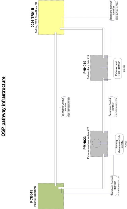
University of Florida Telecommunications Standards
                                                          October 2020 Ed. – Rev. 1 July 2021

      University of Florida Telecommunication Standards
                               October 2020 Edition
                              REVISION 1 (July 2021)

This document is designed to assist certified Information Transport System (ITS)
designers such as Professional Engineers and Registered Communications
Distribution Designers (RCDD®) in the preparation of telecommunications documents
in the appropriate Construction Specifications Institute (CSI) format that will
accompany a full set of Telecommunications drawings for new construction projects,
major renovation projects, and minor renovation projects on the University of Florida
Campus. This document is also intended as a standard by which all low voltage
telecommunications infrastructure shall be installed University wide.

Within University of Florida Information Technology, Infrastructure and
Communication Technology (ICT) is responsible for the maintenance of this
document. Changes to this document shall be made using the change process
specified in the University of Florida Design and Construction Standards, of which this
document is an appendix. Suggested changes to this document or variances from
this standard must be coordinated through the Associate Director of UF IT’s
Infrastructure and Communication Technology at 352-273-1113.

                                                                                 1|Page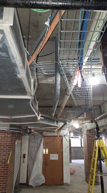
University of Florida Telecommunications Standards
                                                                                                 October 2020 Ed. – Rev. 1 July 2021

                                                       TABLE OF CONTENTS

1.0 INTRODUCTION ........................................................................................................................... 3

2.0 ENTRANCE FACILITY ................................................................................................................. 7

3.0 MAIN TELECOMMUNICATIONS ROOM (MTR) ....................................................................... 10

4.0 TELECOMMUNICATIONS ROOMS .......................................................................................... 13

5.0 BACKBONE PATHWAYS .......................................................................................................... 15

6.0 HORIZONTAL PATHWAYS ....................................................................................................... 17

7.0 WORK AREAS ........................................................................................................................... 19

8.0 BACKBONE CABLE................................................................................................................... 20

9.0 HORIZONTAL CABLE ............................................................................................................... 22

10.0 GROUNDING AND BONDING ................................................................................................ 25

11.0 DELIVERABLES ...................................................................................................................... 26

12.0 VIDEO SPECIFICATIONS GUIDELINES ................................................................................ 29

13.0 OUTSIDE PLANT ..................................................................................................................... 30

14.0 AERIAL PATHWAYS ............................................................................................................... 32

15.0 UNDERGROUND PATHWAYS ............................................................................................... 33

16.0 VAULTS AND PEDESTALS .................................................................................................... 38

17.0 BLUE LIGHT EMERGENCY TELEPHONES ........................................................................... 42

18.0 MASS NOTIFICATION SYSTEM (MNS) ............................................................................... 444

19.0 WIRELESS NETWORKS ........................................................................................................ 466

APPENDIX #1 – UF LABELING AND NAMING CONVENTIONS IN ACCORDANCE WITH
ANSI/TIA-606-B ................................................................................................................................. 48

APPENDIX #2 - GROUNDING AND BONDING .............................................................................. 71

APPENDIX #3 -TELECOMMUNICATIONS ROOM DESIGN EXAMPLES ...................................... 73

APPENDIX #4 - STANDARDS VARIANCE FORM........................................................................... 79

APPENDIX #5 – BLUE LIGHT EMERGENCY PHONE TOWER INSTALLATION........................... 80

APPENDIX #6 – UF ICT, UF HEALTH AND OTHER UF DEPARTMENT SPECIFIC
GUIDELINES ..................................................................................................................................... 81

                                                                                                                                  2|Page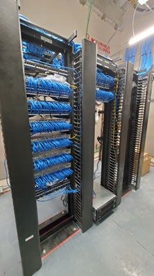
University of Florida Telecommunications Standards
                                                          October 2020 Ed. – Rev. 1 July 2021

1.0 Introduction

1.1 Overview: Communication technologies are a critical element in the design of
all new and renovation building projects. Whether it be voice, data and video
transmission, security and fire alarm systems, building automation systems,
audio/visual systems, or other communication technologies, it is important that a team
of experienced professionals be involved in the design of these complex systems.

A Structured Cabling Plant is a key concept in enabling Information Technology for
UF’s community. In order to maximize network functionality, and to minimize labor and
materials costs, a common set of network codes and standards shall be complied with.
To accomplish this, UF has adopted a policy in which these codes and standards are
managed and administered centrally.        The University of Florida Information
Technology (UF IT) is charged with this responsibility. Specific UF entities have
additional requirements and should be consulted to ensure standards are maintained
(refer to Appendix 6).

1.1.1 Definitions
UF IT: University of Florida Information Technology
UF ICT: University of Florida Infrastructure and Communication Technology
UF ICT Construction Management: These ICT project managers interact with UF
PD&C, architects, and engineers as the owner representative in regards to
Information Technology infrastructure design and construction for renovation and
new construction projects.
UF PD&C: University of Florida’s Planning, Design, and Construction oversees all of
the University’s major and minor construction and renovations.
OSP Manager: the UF outside plant manager is part of the UF ICT Construction
Management team.
UFEM: University of Florida Emergency Management

1.1.2 Old Definitions or Unit Names
UF NS: University of Florida Information Technology’s Network Services unit
UF NS-TNI: University of Florida, Information Technology, Network Services,
Telecommunication and Network Infrastructure group
UF NS-TNI Construction Management: UF IT’s Network Services Construction
Management group. These project managers interact with UF PD&C, architects and
engineers as the owner representative in regards to Information Technology
infrastructure design and construction.
UF NS-TNI Building Network = UF IT’s Network Services Building Network. These
field engineers and technicians actually connect the building wiring to the UF
Network, activate ports, activate wireless access points and maintain the
documentation.

                                                                                 3|Page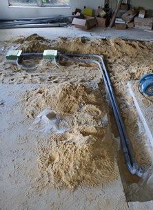
University of Florida Telecommunications Standards
                                                           October 2020 Ed. – Rev. 1 July 2021

1.2    General: Designers shall verify that all applicable portions of these standards
are incorporated into the project’s design, drawings, specifications and final
construction. Requests for variances from these standards shall be submitted in
writing to UF ICT Construction Management. Use the Standards Variance Request
Form found in Appendix 4.

1.3     Telecommunications Projects Eligibility Requirements: All projects
designed by an architect/consulting engineer, shall have the telecommunications
infrastructure designed by the consultant team (Designer) and installed by the
Contractor. This infrastructure shall include all pathways, cabling, terminations,
testing and telecom room construction related to the telecommunications systems.
The Designer shall provide these services in accordance with these standards and as
directed by the UF ICT Construction Management.

1.4     University of Florida’s Final Provisioning Work for all Projects: For all
construction projects for the University of Florida, construction budgets are required
to fund all internal and external telecommunications assets. This includes all wiring,
telecom rooms, connectivity products, electronics, handsets, etc. Furthermore, the
construction budget is required to pay for any additions to outside plant infrastructure
that is needed to support the operation of the building. Designers and Contractors
shall be required to develop construction schedules that allow adequate time for UF
IT or other responsible organizations to complete this final provisioning work, prior to
Substantial Completion and the Owner's occupancy of each part of a project.

1.4.1 Contractors shall be required to cooperate with UF IT personnel and allow them
equal access to the jobsite to inspect and complete any work necessary in the
completion of the project, concurrent with other work underway by the Contractor.

1.5    Codes and Standards: UF’s communications systems shall follow the codes
and standards set forth in the following: NEC, NESC, NFPA, ANSI/TIA
Telecommunications Building Wiring Standards, FCC, IEEE and BICSI’S
Telecommunications Distribution Methods Manual. These codes and standards are
to be used as references when designing telecommunications systems.

1.5.1 The University of Florida promotes the use of widely accepted industry
standards in deploying the University telecommunications infrastructure. Employees
of the university, consultants and contractors working on behalf of the university
should have a working knowledge of these standards prior to performing work for the
university and should follow the university preferred standards and practices while
deploying telecommunications infrastructure. University employees, consultants and
contractors should contact UF ICT Construction Management for clarification and
interpretation of these standards. The following standards are practiced at the
University of Florida:

       •   ANSI/TIA-568-C.0. Generic Telecommunications Cabling for
           Customer Premises
                                                                                  4|Page
University of Florida Telecommunications Standards
                                                             October 2020 Ed. – Rev. 1 July 2021

       •   ANSI/TIA-568-C.1 Commercial Building Telecommunications
           Cabling Standard
       •   ANSI/TIA-568-C.2 Balanced Twisted-Pair
           Telecommunications Cabling and Components Standard
       •   ANSI/TIA-568-C.3 Optical Fiber Cabling Components
       •   ANSI/TIA-569-D- Commercial Building Standard for
           Telecommunications Pathways and Spaces
       •   ANSI/TIA-606-B Administration Standard for the
           Telecommunications Infrastructure. See Appendix 1 for the
           current UF Labeling standard based on ANSI/TIA/EIA-606-B
       •   ANSI/TIA-607-B Generic Telecommunications Bonding and
           Grounding (Earthing) for Customer Premises
       •   ANSI/TIA/-758-B Customer-Owned Outside Plant
           Telecommunications Infrastructure Standard
       •   ANSI/TIA/-862-A Building Automation Systems Cabling
           Standard for Commercial Buildings
       •   ANSI/TIA-942-A Telecommunications Infrastructure
           Standard for Data Centers
       •   NECA 1-Standard Practices for Good Workmanship in
           Electrical Contracting

1.5.2 These standards can be obtained through BISCI at www.bicsi.com as well as
www.tiaonline.org. This manual is based on the version of the standards indicated.
In practice, the most recent version should be used.

1.5.3 These standards are not intended to be used as the final specification or bid
document for any specific new construction. The standards are to be used as a starting
point in a process of collaboration between the architect/designer, the occupant, and
UF IT.

1.5.4 The design team shall include the resources needed to fully develop a complete
scope of work for all telecommunications, information technology and audio/visual
systems and components. The design team must consist of BICSI / RCDD qualified
staff.

1.5.5 All outside plant telecommunications connecting into the UF network conduit
system managed and maintained by UF ICT shall be coordinated with UF ICT
Construction Management. Telecommunications outside plant work (exterior of
facility) must be purchased by the project and coordinated with OSP manager. Any
outside plant work associated with communications shall be provided by the UF ICT
approved and designated underground services contractor. The architect/engineer
shall coordinate with the UF Planning, Design and Construction Project Manager to
eliminate conflicts with other utilities, landscaping, etc., shall include all such work "by
others" in the construction documents, and shall ensure that no gaps exist between
the contractors’ scope of work and the scope(s) of work “by others.”

                                                                                    5|Page
University of Florida Telecommunications Standards
                                                        October 2020 Ed. – Rev. 1 July 2021

1.5.6 Building interior telecommunication installation must be performed by a
contractor who is qualified by UF Infrastructure and Communication Technology and
UF Purchasing under UF Purchasing bid # ITB21KO-103. UF Purchasing maintains
a list of pre-qualified Low-Voltage Contractors.

Follow UFHealth/HealthNet guidelines for low-voltage contractor procurement as
noted in Appendix 6.

1.5.7 Bid Documents: The expected outcome of this collaboration with the design
team is a detailed bid-quality document that contains commonly accepted and
standard language of the industry. These documents are to include a set of
appropriate division specifications per Divisions 25, 27, and 28 of the CSI Master
Format as well as Telecommunications Drawings or Sheets (a.k.a. T-Drawings or T-
Sheets).

                               END OF SECTION

                                                                               6|Page
University of Florida Telecommunications Standards
                                                            October 2020 Ed. – Rev. 1 July 2021

2.0 Entrance Facility

2.1 Overview: The Entrance Facility (EF) is the main telecommunications building
service entrance. It is the area where the demarcation between the inter-building and
intra-building cabling systems is affected. This securable room is to be dedicated to
this purpose with no other building services sharing the space except as noted below.
This room can be collocated with the Main Telecommunications Room (MTR). In the
case of collocation of the Entrance Facility and the Main Telecommunications Room,
the Entrance Facility square footage must be added to that of the Main
Telecommunications Room to accommodate for the entrance conduit, cable, and
breakout.

2.2 Size: A minimum of 35 square feet must be provided to house the Entrance Facility
of a new building. This space may be expanded for larger buildings. If incorporated
into the MTR, allow for the minimum, dedicated Entrance Facility space in the MTR.

2.2.1 Minimum ceiling height is 9' 6", with the bottom of the exposed structure
considered the ceiling. The wall shall extend to the bottom of the exposed structure.
There shall be no suspended ceiling.

2.2.2 All rooms shall be square or rectangular with walls at right angles to each other.
No triangular rooms or walls with curves shall be allowed. No columns shall be allowed
inside the room.

2.3 Location: The service entrance room location shall be as close as practicable to
the point where the electrical facilities enter the building. This room shall be completed
early in the construction phase, so the copper, fiber and broadband feeder cables to
the room can be installed. The room shall be dedicated to Telecommunications
Services.

2.4 Casework in an Entrance Facility: When installing a floor-mounted rack or
cabinet, without panels, fasten the rack or cabinet to the floor and bond the rack or
cabinet to the ground bus. Location of the rack or cabinet will be identified during the
design phase. Two post racks shall be secured to the wall behind them with a ladder
rack.

2.5 Disconnect Modules: The OSP Manager shall coordinate with the public utility
on the installation of the building entrance terminal protectors when the feeder cables
are installed.

2.6 Door: Rooms shall have a fully opening, lockable door opening into an indoor
publicly accessible area. The door shall be at least 36" wide and 80" in height. The
door shall be keyed to match UF’s 5150 key.

2.7 Electrical: Along all walls there shall be one 120Vac/20A electrical duplex outlet
NEMA 520R every 6 ft at 6” AFF per NEC requirements. This should be below the
listed and fire rated backboard.

                                                                                   7|Page
University of Florida Telecommunications Standards
October 2020 Ed. – Rev. 1 July 2021
2.7.1 Along the rear wall of the Entrance Facility or on the ladder connecting the rack
to the back wall (preferred) where the equipment that uses the service will be located,
shall be one 120Vac/20A quad outlet and one 120Vac/30A outlet NEMA L530R. Each
of these outlets shall be on a dedicated circuit and connected to emergency power if
available.
2.7.2 Every electrical outlet shall be labeled with printed labels to indicate the serving
power panel and breaker.
2.7.3 The designers should avoid placing an electrical panel(s) within the wall cavity
adjacent to the telecommunications room.
2.7.4 Electrical panels, except those exclusively for telecommunications equipment,
shall not be located within the telecommunication rooms.
2.8 Grounding: Provide a building ground cable, with bus bar, to the room. Locate
the bus bar at the lower left corner of the listed and fire rated backboard. Refer to
Grounding section of these standards. (See Grounding and Bonding – Appendix 2)
2.9 Identification: The Entrance Facility shall be identified and labeled per UF
Planning, Design, & Construction standard procedures. Room numbers only should
be used where required by applicable security regulations.
2.10 Interior Finishes: To minimize dust, floors shall be of vinyl composition tile or
sealed concrete. All exposed concrete, brick and gypsum board walls shall be painted
or sealed.
2.11 HVAC: Per TIA/EIA Standard. If active electronics are installed in this space,
environmental control system shall maintain temperature between 64 degrees F and
75 degrees F with a relative humidity between 30% and 55%.
2.12 Lighting: Provide a minimum equivalent of 500 lux (50 foot candles) measured
at 1 m (3 ft) above finished floor
2.13 Pathways entering the Entrance Facility: The number and type of
telecommunications circuits that will be brought into the building shall determine the
number and size of inter-building conduits entering this room. The minimum number
and size of conduits to a building is four (4) 4” conduits, with one of the conduits having
four (4) 1” innerducts or a multi-cell fabric innerduct. All service entrance conduits
shall terminate in the service entrance room. For Telecommunications bonding
backbone, a 1” sleeve or conduit is required for proper grounding pathway. All
conduits are required to be fire stopped per NEC.
2.13.1 If the Service Entrance Facility is not serving as the Main Telecommunications
Room for the building then an equal number of 4” conduits must be installed to connect
these rooms. One (1) of these 4” conduits shall contain four (4) 1” innerducts or multi-
cell fabric innerduct equivalent. All service entrance conduits shall terminate in the
service entrance room.
8|PageUniversity of Florida Telecommunications Standards
October 2020 Ed. – Rev. 1 July 2021
2.14 Pathways in the Entrance Facility: A 12 inch, or greater, cable ladder style
tray shall be installed that will encircle the room at 8.5’ AFF. Additionally, trays shall
be installed to service equipment rows, cross-connect areas, and conduits entering
the room. Waterfalls must be installed where cables drop from the cable ladder tray.
2.14.1 Bond each section of the cable tray to the ground bus, or bond each section
to the next and then to the ground bus per NEC. There must be a path from each
section to ground. Location of the cable tray shall be identified by UF ICT Construction
Management during the design phase of the project.
2.15 Plumbing: Entrance Facility shall not have any water pipes within the room's
interior space, routing horizontally on the floor directly above the room, or within the
floor slab below the room.
2.16 Backboard Panels: Each wall shall have listed and fire rated backboard
consisting of 3/4" X 4' X 8' sheets of A-C Grade plywood installed on them for
anchoring termination strips and other devices. The listed and fire rated backboard
panels shall be gray in color with 100% acrylic latex primer/sealer applied to front and
sides of plywood substrate. Labels must clearly indicate the listing and fire resistivity
and be affixed to the backboard.
2.16.1 The backboard shall reach from corner to corner. Install the backboard
vertically at 12" AFF and anchor securely to wall substrate with a minimum of five (5)
equally spaced fasteners along each vertical edge and down the centerline of each
panel. Backboard kits shall include fasteners for masonry, hollow block, steel frame
and wood frame walls. Fasteners must be flush with surface of backboard. Fasteners
shall be of the appropriate type for each substrate. Provide blocking or additional studs
in framed walls to receive backboard panel fasteners.
2.17 Card Key Access and Security: UF Security Policy calls for the protection of
all IT infrastructure, equipment, and hardware located within a building. If a new or
renovated building includes integration of an access control system,
telecommunications rooms shall also be integrated into the access control system for
secure entry and monitoring. Systems employed must match those currently being
deployed throughout campus. UF’s IT Security Policy can be found at
http://www.it.ufl.edu/policies/security/.
END OF SECTION
9|PageUniversity of Florida Telecommunications Standards
October 2020 Ed. – Rev. 1 July 2021
3.0 Main Telecommunications Room (MTR)
3.1.1 Overview: This space provides for the demarcation between inter-building and
intra-building telecommunications service. This area contains the electronic
equipment that transitions between the core campus data, voice and video backbones
and the building backbone. This securable room is to be dedicated to this purpose
with no other building services sharing the space. This space may be co-located with
the Entrance Facility, provided the room is sized for both functions. Main
Telecommunications Rooms are generally considered to be building serving rooms.
3.1.2 A Main Telecommunications Room shall meet all the basic requirements as
those previously indicated for the Entrance Facility. In addition, Main
Telecommunications Rooms will have additional requirements as noted below.
3.2 Size: Each Main Telecommunications Room shall have the minimum size
restrictions based on the overall square footages of the total building area being
served. The following are minimum guidelines – consult UF ICT Construction
Management for approval on final design:
In larger buildings, the size of the TR size should be increased in increments of 10 ft2
for every increase of 100,000 ft2 in gross building area.
Total Building Size in Gross Sq. Ft. Minimum MTR Size
up to 500,000 10' x 12'
Coordinate all final telecom room and space sizing with UF ICT Construction
Management during the design process for the project.
3.2.1 Where a Main Telecommunications Room will also provide service as an
Entrance Facility or Telecommunication Room, the minimum size of the room shall be
determined by summing the square footage requirements of all services that will be
supplied by that room.
3.2.2 Security access control panels: Where a Main Telecommunications Room
may house security access control panels, the minimum size of the room shall be
provided, in fact, larger rooms may be needed depending on the amount of equipment
proposed. Coordinate wall mounting of access control panels with UF ICT
Construction Management prior to installation. No servers or other ancillary security
equipment shall be installed in Telecommunication Rooms. Security panels shall have
their own power source and additional power should be designed into
Telecommunications Rooms that house access control panels. Submit variance
request (Appendix 4) to mount security access control panels into Telecommunication
Rooms as a means to confirm adequate space is available.
3.3 Location: The Main Telecommunications Room shall be located to ensure that
the room has access to the intra- and inter-building backbone pathway, is accessible
for delivery of equipment, away from potential sources of EMI, away from machinery
10 | P a g eUniversity of Florida Telecommunications Standards
October 2020 Ed. – Rev. 1 July 2021
that causes vibration, and away from steam pipes, drains, and clean-outs. If the Main
Telecommunications Room is on a different floor than the Entrance Facility, it should
be vertically aligned above the Entrance Facility Room.
3.4 Casework in the Main Telecommunications Room: Install 7’ racks or cabinets,
without panels, to support video, voice and data network termination devices and
electronics. All data equipment shall be rack-mounted and the infrastructure design
should reflect this. The amount of service required to support the building might
require more than one rack or cabinet to be installed. Fasten the rack(s) or cabinet(s)
to the floor and bond the rack or cabinet to the ground bus.
3.4.1 Number and location of the racks or cabinets shall be supplied during the design
phase of the project (see Telecommunications Room Examples – Appendix 3). Two
post racks shall be secured to the wall behind them with a ladder rack. A good working
environment for a telecommunications room includes at least three feet of clear space
extending out from the front of the equipment mounted on a wall and at least three
feet out from the front and back of equipment mounted in a rack with two feet of
clearance on each side.
3.4.2 All racks and cabinets shall be provided with cable management for horizontal
and backbone cabling. (See Telecommunications Room Examples Appendix 3).
3.5 Disconnect Modules: As per Entrance Facility.
3.6 Door: As per Entrance Facility.
3.7 Electrical: For every rack included in the design, there shall be one 120Vac/20A
quadplex outlet and one 120Vac/30A electrical outlet NEMA L530R at 90" AFF behind
the proposed rack location(s) or installed on the rack (preferred). Each of these outlets
shall be on a dedicated circuit.
3.7.1 Along all walls there should be one 120Vac/20A electrical duplex outlet every 6
ft at 6” AFF. This should be below the listed and fire rated backboard.
3.7.2 A dedicated circuit shall serve every outlet that provides electrical service to
networking equipment, such as switches or power supplies. This is not necessary for
the general service outlets 6” AFF. Every electrical outlet shall be labeled with printed
labels to indicate the serving power panel and breaker.
3.7.3 If standby power is or will be available, the electrical circuits for the racks shall
be included in optional standby power design.
3.9 Grounding: As per Entrance Facility.
3.9 HVAC: Equipment Rooms that house electronics shall have a HVAC source to
maintain continuous control of temperature and humidity (24 hours per day, 365 days
per year). The ITS designer must consider the heat produced by each piece of
11 | P a g eUniversity of Florida Telecommunications Standards
October 2020 Ed. – Rev. 1 July 2021
equipment (the BTU rating) that will be placed in each Equipment Room. The final
Equipment Room design must accommodate any special or specific requirements for
heating and cooling. Temperature and humidity shall be controlled at 64 to 77 degrees
(F) and 40% to 55% RH respectively. Additionally, design as needed heat dissipation
of 5000 BTU/hr per cabinet to accommodate installed electronics. Consider a
dedicated HVAC source for the Telecommunications Room if more energy efficient to
operate than using the building’s general HVAC system.
• Temperature: 18 – 27°C (64 – 81°F)
• Maximum relative humidity (RH): 60%
• Minimum dew point: 5.5°C (42°F)
• Maximum dew point: 15°C (59°F)
3.9.1 HVAC Location: The installed location of the HVAC unit and pipes feeding the
unit shall be designed to minimize risk of dripping fluids on the network electronics
and shall not be above the network electronics rack.
3.10 Identification: As per Entrance Facility.
3.11 Interior Finishes: As per Entrance Facility.
3.12 Lighting: Provide a minimum equivalent of 500 lux (50 foot candles)
measured at 1 m (3 ft) above finished floor.
3.13 Pathways entering the Main Telecommunications Room: If the Entrance
Facility room is not serving as the Main Telecommunications Room for the building
then an equal number of 4” conduits must be installed to connect these rooms. One
(1) of these three (3) 4” conduits shall contain four (4) 1” innerducts.
3.13.1 A minimum of three (3) 4” conduits shall be installed between each
Telecommunications room and the Main Telecommunications Room.
For Telecommunications bonding backbone, a 1” sleeve or conduit is required for
proper grounding pathway. All conduits are required to be fire stopped per NEC.
3.14 Pathways in the Main Telecommunications Room: As per Entrance Facility.
3.15 Plumbing: As per Entrance Facility.
3.16 Listed and Fire Rated Backboard Panels: As per Entrance Facility.
3.17 Card Key Access and Security: As per Entrance Facility.
END OF SECTION
12 | P a g eUniversity of Florida Telecommunications Standards
October 2020 Ed. – Rev. 1 July 2021
4.0 Telecommunications Rooms
4.1 Overview: These rooms provide for demarcation between the per-floor horizontal
service distribution cabling and the building video, data, and voice backbone cabling.
A Telecommunications Room provides the connection point between the building
backbone and horizontal distribution pathways. These securable rooms are to be
dedicated to this purpose with no other building services sharing the spaces (except
as noted below in paragraph 4.2.1 for the security panels). A Telecommunications
Room may be co-located with the Entrance Facility and/or Main Telecommunications
Room provided the room is sized for both functions.
4.2 Size: For new construction the preferred size is a 10' x 12' room with one door
opening into a major publicly accessible hallway. For renovations where the preferred
design is not possible, a 5' x 14' room with two sets of double doors with each set
providing a 6’ opening on the 14' wall of a major publicly accessible hallway (the doors
must swing into the hallway) may be used. The second design uses the hallway as
temporary space during times of maintenance and is most practical in low traffic
hallways such as office areas.
4.2.1 Security access control panels: As per Main Telecommunications Room.
4.3 Location: A Telecommunications Room shall be centrally located in reference to
the area it serves. This is to minimize the horizontal cable lengths and duplication of
electronic equipment.
4.3.1 At a minimum, a Telecommunications Room shall be provided for each floor of
the building. The Telecommunications Rooms should be located above each other
on the different floors. If the Telecommunications Rooms are not stacked, the
Telecommunications Room shall have a means to access the Telecommunications
Rooms on the floor above and below via metal conduits or sleeves.
4.3.2 Maximum distance between the Telecommunications Room on each floor and
a telecommunications work area data outlet is 295 feet, as measured per the cable
pathway.
4.4 Casework: As per Main Telecommunications Room.
4.5 Disconnect Modules: As per Entrance Facility.
4.6 Door: As per Entrance Facility unless a special room size is approved.
4.7 Electrical: As per Main Telecommunications Room.
4.8 Grounding: As per Entrance Facility.
4.9 HVAC: As per Main Telecommunications Room.
4.10 Identification: As per Entrance Facility.
13 | P a g eUniversity of Florida Telecommunications Standards
October 2020 Ed. – Rev. 1 July 2021
4.11 Interior Finishes: As per Entrance Facility.
4.12 Lighting: As per Entrance Facility.
4.13 Pathways Entering the Telecommunication Room: If the Telecommunications
Rooms are stacked one above another, three (3) 4” sleeves shall be installed between
each Telecommunications Room. Should Telecommunications Rooms not be
stacked, a minimum of three (3) 4” conduits shall be installed between each
Telecommunications Room and the Main Telecommunications Room. For
Telecommunications bonding backbone, a 1” sleeve or conduit is required for proper
grounding pathway. All conduits are required to be fire stopped per NEC.
4.14 Pathways in the Telecommunication Room: As per Main Telecommunications
Room.
4.15 Plumbing: As per Entrance Facility.
4.16 Listed and Fire Rated Backboard Panels: As per Entrance Facility.
END OF SECTION
14 | P a g eUniversity of Florida Telecommunications Standards
October 2020 Ed. – Rev. 1 July 2021
5.0 Backbone Pathways
5.1.1 Overview: Communications conduit requirements depart from that for “normal”
electrical power distribution. Communications conduit sizing does not follow NEC in
terms of the maximum number of conductors allowed per unit volume. Due to the need
for facilitating frequent additions, moves and changes to the telecommunications
systems, communications conduits are generously sized larger.
5.1.2 Conduits serving as a backbone pathway for telecommunications cables are a
minimum of 4”. Conduits serving as a pathway for grounding conductors are a
minimum of 1”.
5.1.3 Conduits shall be used to feed the Entrance Facility from the Outside Plant
(OSP). Conduits or sleeves shall be used to connect the Entrance Facility to the Main
Telecommunications Room. Conduits or sleeves shall be used to connect the Main
Telecommunications Room and the Telecommunications Rooms.
5.2 Entrance Facility Conduits: Reference the Outside Plant section (of this
standard for complete design guidelines. The following shall only act as a general
guide for initial backbone pathway considerations.
5.2.1 A minimum of four (4) 4” conduits shall be used to provide connections from the
Outside Plant into the Entrance Facility. One of these conduits shall be supplied with
four (4) 1” innerducts.
5.2.2 Conduits entering the building are a minimum of 4" in size with some type of
sub-space partitioning.
5.2.3 Conduits shall terminate 1” to 3” inside the Entrance Facility per TIA-569-B and
be reamed and bushed.
5.2.4 All Entrance Facility conduits shall be sealed so as to be water and gas tight
after installation.
5.2.5 Conduits shall not contain more than two 90-degree bends and be placed with
a minimum of ¼ inch per foot slope, away from the Entrance Facility, to allow proper
water drainage from the ducts.
5.2.6 If the Main Telecommunications Room is not also functioning as an Entrance
Facility, conduits or sleeves of equal number and size shall be installed from the
Entrance Facility into the Main Telecommunications Room.
5.2.7 An additional 1” conduit or sleeve shall also be provided from the Entrance
Facility to the Main Telecommunications Room to provide a pathway for the
Telecommunications Bonding Backbone cable.
15 | P a g eUniversity of Florida Telecommunications Standards
October 2020 Ed. – Rev. 1 July 2021
5.3 Main Telecommunications Room Conduits: A minimum of three (3) 4” conduits
or sleeves shall be installed between the Main Telecommunications Room and each
individual Telecommunications Room.
5.3.1 One (1) 1” conduit or sleeve shall be installed between the Main
Telecommunications Room and the Telecommunications Room. The
Telecommunications Bonding Backbone cable shall use this conduit or sleeve.
5.4 Telecommunications Room Conduits: A minimum of three (3) 4” conduits or
sleeves shall be installed between the Main Telecommunications Room and each
individual Telecommunications Room.
5.4.1 One (1) 1” conduit or sleeve shall be installed between each
Telecommunications Room and the one above. The Telecommunications Bonding
Backbone cable shall use this conduit or sleeve.
5.4.2 Conduits between building telecom rooms shall be a minimum of 4" in size.
END OF SECTION
16 | P a g eUniversity of Florida Telecommunications Standards
October 2020 Ed. – Rev. 1 July 2021
6.0 Horizontal Pathways
6.1 Overview: The standards adopted by this University provide that a clear and
accessible pathway for horizontal telecommunications cabling be provided. These
pathways are located between the Telecommunications Rooms and the rooms
containing the telecommunications outlets. The Design Team shall prepare
Telecommunications drawings and specifications that ensure a clear and accessible
pathway for telecommunications cabling. Any pathway that is not accessible or does
not provide a clear and workable pathway will be rejected.
6.1.2 There are several methods available for providing a pathway for supporting
telecommunications cables. The architectural design of each building is unique and
requires an analysis of which method(s) are best suited for that building.
6.1.3 Only conduits run directly from the Telecommunications Room to the Work Area
Outlet or Cable Trays with Work Area feeding conduits are accepted for horizontal
pathways. “J hooks” or other similar types of cable pathway devices shall not be used
in any new construction or major renovation project design. MUTOA’s, CP’s, and TP’s
must be approved through UF ICT Construction Management before installation.
6.2 Cable Trays: Cable Trays are the preferred pathways for supporting horizontal
telecommunications cables. Cable trays shall be provided from the
Telecommunications Rooms to support the horizontal cabling.
6.2.1 The minimum cable tray width is 12” and minimum cable tray depth is 4”. The
actual cable tray size(s) shall be determined during the design phase of the project.
The cable tray shall be installed in accordance with the applicable electrical code. The
cable tray is to be dedicated for use only by low-voltage cabling systems. Cable tray
should be trapeze supported or wall mounted. If wall mounted, additional threaded
rod supports should be provided from the ceiling to the outer edge of the wall mounted
tray. Center support cable trays shall not be accepted.
6.2.2 Cable Trays should have devices installed at all inside corners to prevent
minimum cable bending radius from being exceeded.
6.2.3 The specification for this cable tray shall be provided along with the design
layout.
6.2.4 Cable tray clearances shall follow ANSI/TIA 569-D Standards.
6.3 Horizontal Conduit: Conduit may feed WAO boxes directly from the
Telecommunications Room (home-run). Conduits shall not run continuously for more
than 100’ before installing a pull box.
6.3.1 Conduits shall not contain more than two 90-degree bends without a pull box.
Directional changes shall be made outside pull boxes. At no time shall a pull box be
accepted in favor of a bend in the conduit.
17 | P a g eUniversity of Florida Telecommunications Standards
October 2020 Ed. – Rev. 1 July 2021
6.3.2 Label all conduits as per UF Labeling Standard. (See UF Labeling Standard in
Appendix 1) Label all pull and junction boxes with the letters IT (See UF Labeling
Standard in Appendix 1).
6.3.3 A minimum of one (1) 1” conduit shall connect from the work area outlet box to
the nearest cable tray. Conduits connecting a Work Area Outlet and the Cable Tray
shall terminate within 4” and above the cable tray. Conduit fills shall not exceed 40
percent of the conduit capacity.
6.3.4 Conduits shall be reamed and bushed.
6.3.5 Each conduit shall contain a nylon pull cord with a 200 LB pulling tension.
6.4 Prohibited Components: No LB type fittings of any size are to be used for
communication conduit. No PVC conduit or PVC sleeves are to be used for
communications conduit within the confines of a building.
6.5 Conduit Grounding: Horizontal pathway conduits shall be grounded to the cable
tray to ensure a proper grounding path. This may be accomplished by bonding the
conduit to the cable tray, using a grounding strap, and/or a grounding bushing.
END OF SECTION
18 | P a g eUniversity of Florida Telecommunications Standards
October 2020 Ed. – Rev. 1 July 2021
7.0 Work Areas
7.1 Overview: Design of Work Area Outlets (WAO) change more often than any
other piece of the design process. Different needs demand different solutions. As
such, this section details only the most basic requirements and innovative designs
that keep these minimal standards in mind are acceptable.
7.2 WAO Cable Count: A Work Area Outlet must be able to support at least two
unshielded twisted pair (UTP) cables to support telecommunications needs.
Customer and department needs will dictate the number of connections needed;
however, the minimum is two cables per WAO. WAO dedicated to serving a wireless
access point (WAP) need two cables as well. IP cameras and emergency notification
speakers may have a single cable.
7.3. WAO Rough-in: Telecommunications outlet boxes installed in drywall, plaster,
or concrete block wall must be at least 4 X 4 inches and 2.5 in. deep. All work-area
outlet boxes should have a single-gang ring.
7.3.1 Floor boxes pose several future issues. The design team should plan a pathway
to the floor box that allows future accessibility while following horizontal pathway bend
radius and pull box requirements. Floor boxes have proprietary inserts for data
communications parts that need to be purchased by the project and furnished to the
UFIT qualified low-voltage contractor.
7.3.2 Modular furniture also poses an issue if the data cables are to be integrated into
the furniture. A permanent pathway between the wall or floor and the furniture needs
to be designed and installed in accordance with horizontal pathway bend radius and
pull box requirements. The use of “whips” is fine but must be coordinated up front to
ensure that no scope gaps occur.
7.4 WAO Room Count: All office areas should have at least two Work Area Outlets.
These outlet boxes shall be installed on opposing walls. Customer and department
needs may require additional locations to meet the users’ needs.
7.5 WAO for Wireless: In conjunction with UF IT, the design team should conduct
a wireless survey and design the wireless system. One work area outlet (with a
minimum of 2 cables) shall be dedicated to each wireless access point location. See
Section 19.0 Wireless Networks for additional design requirements.
7.6 WAO Conduit: See Horizontal Pathway section of this standard for conduit
requirements.
7.7 WAO Labeling: Label all work area outlets (WAO) and WAO terminations.
(See UF Labeling Standard in Appendix 1).
7.8 WAO Video Needs: See Video section of the standard for details on video
cabling and pathways requirements.
END OF SECTION
19 | P a g eUniversity of Florida Telecommunications Standards
October 2020 Ed. – Rev. 1 July 2021
8.0 Backbone Cable
8.1 Overview: The building backbone system connects Telecommunications Rooms
to each other, to the Main Telecommunications Room and the Main
Telecommunications Room to the Entrance Facility. UF specifies several separate
cable systems to provide for the data, video and voice needs of the building occupants.
Riser-rated twisted-pair copper multi-pair cables, coax, and both single-mode and
multi-mode fiber along with their termination systems are specified.
8.2 Entrance Facility to Main Telecommunications Room Backbone Cable:
Where an Entrance Facility is not collocated with the Main Telecommunications Room
the backbone cables connecting these two rooms shall be equal in content to the
cables provided to the Entrance Facility from the Outside Plant. These cables may
differ in composition (i.e., rated for interior use) than the entrance backbone cable
shall have a pair count, strand count and so on, sized for the needs of the building.
8.3 Copper Cable Backbone: UF is migrating away from analog telephone signal
distribution. Installation of a copper cable backbone will be decided on a case-by-
case basis. Please consult the ICT project manager to determine if installation is
necessary. If necessary, a minimum of one 25-pair category-5e or better riser cable
shall be installed from the Main Telecommunications Room to each
Telecommunications Room. Building design, use and/or services may dictate
additional pairs for riser cable needs.
8.4 Copper Cable Testing & Records: The contractor shall provide the following
electrical test records per the Deliverables section of this document for all backbone
copper cables:
a. Continuity tests on all pairs (test for opens).
b. Test for crosses and shorts, on all pairs.
c. Test for loss at 100.4 MHz, on all pairs.
d. Test for noise metallic and noise to ground, sampling can be used.
e. Test for insulation resistance, sampling can be used.
8.5 Fiber Optic Cable Backbone: A minimum fiber optic intra-building backbone
cable consisting of 12-strand 50-micron OM-4 laser optimized and a 12-strand single-
mode shall be installed from the Main Telecommunications Room to each individual
Telecommunications Room.
8.6 Installation: The fiber-optic backbone cables shall be terminated at all locations
in a rack-mounted fiber panel. There shall be 10 ft. of jacketed cable slack managed
outside of the fiber panel to facilitate future re-terminations. This is typically placed in
the cable tray. There shall be 3 ft. of slack (with the outer jacket removed) managed
inside the fiber panel.
8.6.1 Terminate all fiber strands via fusion splicing and pig-tail style connectors.
20 | P a g eUniversity of Florida Telecommunications Standards
October 2020 Ed. – Rev. 1 July 2021
8.7 Fiber Optic Cable Testing: The contractor on all backbone fiber cables shall
provide the following documentation and tests records for each fiber-optic cable
installed:
a. Identifier as specified by UF Labeling standard (See Appendix 1)
b. Termination fiber panel identifiers for both sides of the cable.
c. Total fiber-strand type and count in the cable
d. Distance in meters for actual cable length
e. Test for end-to-end dB loss, both directions, at 850 nm and 1300 nm
for multimode and 1310 nm and 1550 nm for single mode for each
individual fiber strand.
8.7.1 End to end loss measurements shall be made with a power source and light
meter. Multi-mode fiber measurements shall be tested in accordance with ANSI/TIA/-
526-14-A method B. Single mode fiber measurements shall be tested in accordance
with ANSI/TIA/-526-7 method A.1. Maximum allowable loss:
Maximum allowable loss for splices is .15 dB
Maximum allowable loss for connectors is .5 dB per pair
8.8 CATV Backbone: See Video Specification Guidelines, Section 12.0.
END OF SECTION
21 | P a g eUniversity of Florida Telecommunications Standards
October 2020 Ed. – Rev. 1 July 2021
9.0 Horizontal Cable
9.1 Overview: To satisfy today’s telecommunications requirements, the horizontal
cabling shall be planned to reduce on-going maintenance and relocation. It shall also
accommodate future needs since horizontal cabling is often much less accessible than
the backbone cabling. In keeping with this effort, Category6A unshielded twisted pair
(UTP) cabling or better shall be installed in all new construction and major renovations
university wide. The cable must also be certified by UL with the limited power (LP)
rating. The time, effort, and skills required for changes can be extremely high. In
addition, access to the horizontal cabling frequently causes disruption to occupants
and their work. These factors make the choice and layout of horizontal cable types
very important to the design of the building cabling. Consideration should be given to
accommodating a diversity of user applications in order to reduce or eliminate the
probability of requiring changes to the horizontal cabling as user needs evolve.
9.2 Cabling Distance: The cable run from the Telecommunications Room to the
WAO, consisting of a minimum of two cables, shall not exceed 295 feet and contain
no splices. These cables are to provide service for both voice and data
communications as an integrated telecommunications system.
9.3 Cable Installation: Installation and physical protection of Category 6A cable is a
critical element for the cable to deliver its rated bandwidth. A "kink", "pinch", a bend
radius less than 1.25 inches in diameter, or the manufacturers specified bend radius,
or stretching of the cable by exceeding the 25 pound maximum pulling tension during
installation will damage the cable to the point that it will not meet rated specifications
and shall be replaced.
9.3.1 No open or exposed wiring or conduits shall be permitted below finished
ceilings.
9.4 Cable Termination: All UTP horizontal cable should be terminated to T568A
pinout. Requirements for terminating Category 6A cable requires that no more than
the minimum amount of the common sheath be removed than is required for
termination and no more than 1/2 inch of untwisting of conductors.
9.4.1 Horizontal cables shall terminate in a rack-mounted patch panel in the
Telecommunications Room. Horizontal cables reserved specifically for non IP-based
telephone systems shall terminate into a 110-field termination block. An example
would be elevator phone, fire alarm phone, and blue light phone wires.
9.4.2 When designing the layout of the Telecommunications Rooms rack-mounted
patch panels, racks, UPS’s, etc., reference the example provided in this standard.
(See Telecommunications Room Example in Appendix 3).
22 | P a g eUniversity of Florida Telecommunications Standards
October 2020 Ed. – Rev. 1 July 2021
9.5 Cable Slack: At the Work Area Outlet, there shall be 12” of slack after termination
to facilitate future re-terminations.
9.5.1 In the Telecommunications Room, the cable shall reach the punch-down patch
panel and have 10’ of slack. Coordinate with UF ICT Construction Management on
the placement of the managed slack.
9.6 Cable Type: All data and voice horizontal cables shall be unshielded twisted-pair
cable, each consisting of four twisted pairs of solid conductors type CMR or CMP (as
specified by code, the plans, or engineer of record), Category 6A or better for all new
construction and major renovation projects (as specified by UF ICT). The preferred
type of communication cable shall be approved by the UF IT Representative during
the design phase of each project.
9.7 Clearances: The installation of these data and voice cables shall conform to the
following clearances:
a. At least 127 millimeters (5 inches) from power lines carrying 2KVA or
less
b. At least 305 millimeters (12 inches) from power lines carrying from 2 to
5KVA
c. At least 915 millimeters (36 inches) from power lines carrying more
than 5KVA
d. At least 127 millimeters (5 inches) from all fluorescent lights and other
sources of electromagnetic interference
9.8 Conference Rooms: (See Video Specification Guidelines, Section 12)
9.9 Horizontal cable testing and records: Each cable shall have a permanent link
test performed. For Category-6A-rated links a level IIIe tester must be used to certify
the cable to 500 MHz. All testers shall be manufacturer certified annually to ensure
accuracy.
9.10 Identification: Each cable shall be labeled on each end with an appropriate
cable identifier (i.e., 1A-1A01) (See UF Labeling Standard in Appendix 1).
9.11 Elevator Communications: A single horizontal UTP cable shall be installed to
support elevator telephone and emergency communications. There shall be a means
of disconnecting and testing the telephone line at or adjacent to the elevator control
panel.
9.12 Energy Management Systems: Those energy management systems
employing the campus data network for communication shall install their physical
infrastructure in accordance with these University Telecommunications standards.
23 | P a g eUniversity of Florida Telecommunications Standards
October 2020 Ed. – Rev. 1 July 2021
9.13 Other low voltage cabling systems: Other low voltage cabling systems must
adhere to the telecommunications standards as well. These cables may share the use
of common cable trays as needed. These types of cables include, but are not limited
to, HVAC control cables, fire control cables, and security systems cables.
9.13.1 If other low voltage systems are to use the campus data network for
communicating, these systems must also conform to the campus telecommunications
standards. All low voltage systems using the UF network shall be inspected by UF
ICT Construction Management for compliance with these standards.
END OF SECTION
24 | P a g eUniversity of Florida Telecommunications Standards
October 2020 Ed. – Rev. 1 July 2021
10.0 Grounding and Bonding
10.1 Overview: All cabling systems and electronics-distribution equipment shall be
grounded for both safety and minimization of electromagnetic interference.
Specifications for this are found in this section. Telecommunications grounding
systems are composed of Telecommunications Bonding Backbones (TBB) and
Telecommunications Grounding Bars (TGB). Bonding requirements for
Telecommunications at the University of Florida follow the ANSI/TIA607-B standard.
10.2 TBB Grounding Wire: The TBB shall be a green insulated grounding wire with
a minimum size of 6 AWG.
END OF SECTION
25 | P a g eUniversity of Florida Telecommunications Standards
October 2020 Ed. – Rev. 1 July 2021
11.0 Deliverables
11.1 Overview: Architects and contractors have come to accept the rigid industry
standards that data communications / information transport systems impose. To a
large degree, specialized skill sets are required for the design and installation of these
systems and the technology of telecommunications cabling continues to advance
dramatically. For this reason UF requires a Registered Communications Distribution
Designer (RCDD) on the installation team. Additionally, the installed systems must be
documented in a way that allows for minimal ongoing labor in the maintenance and
management of the installed system.
11.2 Telecommunication Contractor's Obligations: If not owner procured, the
contractor shall furnish all material required for a complete structured cabling system,
including installation of communication cables, installation of communication outlets,
and termination of all cables in the Entrance Facility, the Main Telecommunications
Room, and Telecommunications Rooms. The contractor shall install all of this
material per these standards.
11.2.1 The contractor shall test and certify all cable and provide documented results
of the testing. If any cable run tests defective, the contractor shall replace defective
cable.
11.2.2 A one-year materials and labor warranty shall be provided on all cable and
hardware installed by the telecommunications contractor. This shall be in addition to
any and all factory warranties that can be provided.
11.3 As-Built Drawings and Information: The Contractor shall prepare and submit
record drawings at an appropriate scale (1/16” or 1/8” preferred in PDF -- follow UF
Design Services Guide) using an acceptable electronic media format. The record
drawings shall convey the following information:
a. Locations and Identifiers of all work area outlets.
b. All horizontal pathway elements including but not limited to cable tray
and conduit.
c. Location and identifiers of all Entrance Facilities, Main
Telecommunications Rooms, Telecommunications Rooms.
d. All backbone pathway elements.
e. Emergency speakers, emergency phones, and wireless access points.
11.4. Test Results and Documentation Required: As a condition of Substantial
Completion, the Contractor shall be responsible for providing the following information:
26 | P a g eUniversity of Florida Telecommunications Standards
October 2020 Ed. – Rev. 1 July 2021
11.4.1 Concerning the horizontal cable installation:
a. Complete test results for each horizontal cable. This test information
shall be delivered in electronic, Fluke® Linkware™ compatible format.
b. A cable record for each horizontal cable including the following
information:
i. Cable identifier as per UF labeling standard (see Appendix 1)
ii. Termination point on the host end identified as per UF labeling
standard (see Appendix 1)
iii. Termination point on the user end identified as per UF labeling
standard (see Appendix 1)
iv. Termination hardware used at the host end (patch panel type)
v. Termination hardware used at the user end (outlet jack type)
vi. Cable type and manufacturer’s specification sheet for the cable
vii. Presence of a CP, TP, or MUTOA
11.4.2 Concerning the backbone and entrance fiber cable installation:
a. Complete test results for each backbone fiber cable strand. This test
information shall be delivered in electronic, Fluke® Linkware™
compatible format.
b. Provide complete path record for newly installed backbone OSP cable
per Appendix 1.
c. An electronic copy of every insert supplied with every fiber panel
d. A cable record for each fiber cable including the following information:
i. Cable identifier as per UF labeling standard (See Appendix 1)
ii. Termination point on the first end identified as per UF labeling
standard (see Appendix 1)
iii. Termination point on the second end identified as per UF
labeling standard (see Appendix 1)
iv. Length of the fiber cable
v. Fiber strand count in the individual cable
e. Cable manufacturer’s specification sheet for the cable
11.4.3 Concerning the terminals of UF-owned entrance copper cable:
a. Each terminal identifier
b. Quantity and type of protectors
c. Quantity and type of termination blocks
d. Cable identifier and pairs entering or leaving
(section continued next page)
27 | P a g eYou can also read