PROLASER ELECTROTA Model No. 8991 - Self-leveling Rotary Laser Level - Kapro
←
→
Page content transcription
If your browser does not render page correctly, please read the page content below
PROLASER® ELECTROTA™
                  Self-leveling Rotary Laser Level
                  Model No. 8991
                     User Manual
                     Manual del usuario
                     Manuel d'utilisation

                             Rechargeable   4 x C type
Up to 300m/980'                batteries
       165'/50m                              included
with detector                   included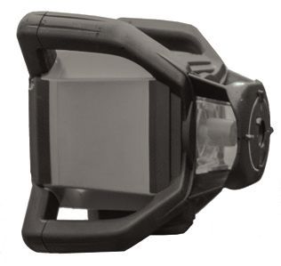
EN

    Thank you for purchasing the Prolaser® Electrota™ 8991 Self-
    Leveling Rotary Laser Level. You are now the owner of one of
    our innovative, state of the art tools. These tools incorporate
    new laser technology, enabling the professional user and the
    serious DIY enthusiast to achieve accurate results and reduce
    valuable work time.

    APPLICATIONS
    The Prolaser® Electrota™ 8991 has been designed for use in
    most areas of construction, for example:
    • Laying foundations
    • Wall and fence construction
    • Laying sloped water and sewage lines
    • Laying flooring
    • Hanging acoustic ceilings
    • Installing partitions and drywall

                                       Rechargeable   4 x C type
    Up to 300m/980'                      batteries
           165'/50m                                    included
    with detector                         included

              NOTE

       Keep this user manual for future reference.

2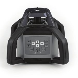
CONTENTS
•   Features                            4
•   Safety instructions                 5-6
•   Overview                            7-8
•   Operating Instructions              9-16
    Horizontal Plane (Automatic Mode)   9
    Inclined Plane                      10
    Manual Mode                         11
    Vertical Setup                      12
    Plumb Down                          13
    Scan Function                       13
    Manual Rotation                     14
    Automatic Drift System              14
    Laser Detector                      15
    Using the Laser Detector            15
    Using the Remote Control            16
•   Power Supply                        17-18
•   Care and Maintenance                19
•   Field Calibration Test              20-21
•   Specifications                      22
•   Warranty                            23
                                                3
FEATURES
• Self-leveling electronic mechanism on slopes of ±5°
• 360° rotation generates a horizontal or vertical level plane
• Generates an inclined plane of up to ±5° in both the X and
Y planes
• Five variable speeds (0, 60,120, 300, 600 rpm)
• Scan modes create visible laser lines
• Supplied with rechargeable batteries and battery
Charger-AC/DC Converter
• IP-65 rated for water and dust resistance
• Plumb Down/Plumb Up point
• Rugged design with protective handles.
• Freestanding or fits onto standard tripod (5/8" thread)
• Remote control included
• Laser Detector included
• Shockproof protective case included
• Laser beam enhancement Beamfinder® glasses included
NOTE
This device contains precision components
that are sensitive to external shock, impact or
falls which may compromise its functionality
–handle with care to maintain its accuracy.
4SAFETY INSTRUCTIONS
WARNING
This product is emitting radiation that is classified
as class II according to EN 60825 -1
The laser radiation can cause serious eye injury
• Do not stare into the laser beam
• Do not position the laser beam so that it unintentionally
blinds you or others.
• Do not operate the laser level near children or let children
operate the laser level.
• Do not look into a laser beam using magnifying optical
devices such as binoculars or a telescope, as this will
increase the level of eye injury.
WARNING: This product contains lead in solder and
certain electrical parts contain chemicals which are
known to the State of California to cause cancer, birth
defects or other reproductive harm.
(California Health & Safety Code Section 25249.6- Proposition 65)
NOTE
The red goggles are intended to enhance the
visibility of the laser beam. They will not
protect your eyes against laser radiation.
5• Do not remove or deface warning labels on the laser level.
• Do not disassemble the laser level.
• Do not drop the laser.
• Do not use solvents to clean the laser.
• Do not use in temperatures below -20°C or above 50°C
(-4°F / 122°F)
• Do not operate the laser in explosive atmospheres such as
flammable liquids, gases or dust. Sparks from the tool can
cause ignition.
• When not in use remove the batteries, engage the
pendulum lock and place the laser in the carrying case.
• Make sure the pendulum lock mechanism is engaged
before transporting the laser.
NOTE
If the laser level is not in use for a prolonged
period of time, remove the batteries from the
battery compartment to prevent leakage or/
and corrosion damage.
If the pendulum lock mechanism is not
engaged before transportation, internal
mechanical damage may occur.
6OVERVIEW
Main body
1. Laser Diode.
2. Plumb Up Beam window.
3. Control Panel.
4. Carrying Handle.
5. Charger socket.
7Control Panel
1. Rotation left
2. Rotation right
3. Manual/Auto (in manual mode the self leveling is disabled)
4. Power On/Off
5. Automatic drift system
6. Rotation Speed Control
7. Direction Scanning
8. Y-AXIS
9. X-AXIS
8OPERATING INSTRUCTIONS
To get the most out of your Prolaser® Electrota™ 8991, please
adhere carefully to the following instructions.
Note: Avoid setting up the laser near heavy machinery or sources
of vibration that may adversely affect the leveling of the laser.
Horizontal Plane (Automatic Mode)
Place the Rotary Laser on a dry, flat, vibration free surface or or
on a standard 5/8" tripod (not included) or ceiling to floor leveling
pole (not included) or on any wall mount accessory (not included).
1. Set up the Rotary Laser approximately level; the instrument
can compensate for up to ±5° from the horizontal plane.
2. Press the On/Off button. The power indicator will light up
and the laser beam will blink. If the instrument is set up outside
the ±5° limit, the manual indicator will blink and rotation will not begin.
3. Verify that the Rotary Laser is in automatic mode - the manual
indicator must be unlit.
4. The Rotary Laser is ready to work when the laser beam no
longer flashes. The instrument is now level and the laser
head will rotate at 600 rpm.
5. To make the beam more visible, change the rotating speed
(see page 13), change scanning mode (see page 14), or
use the Laser Detector to detect the laser beam (see page 15).
6. You can use the remote control to control the Rotary Laser
(see page 16). This option is very useful for trench work or
when laying concrete.
7. To turn the Rotary Laser off, press the On/Off button.
9Inclined Plane
The Rotary Laser can be set up to create a single or dual
directional inclined planed at ±5° from the horizontal plane. This
is very helpful for laying inclined concrete surfaces, ensuring run-
off pathways as well as laying water and sewage lines.
1. Set up the Rotary Laser approximately level; the instrument
can compensate for up to ±5° from the horizontal plane.
2. Press the On/Off button. The power indicator will light
up and the laser beam will blink. If the instrument is set
up outside the ±5° limit the manual indicator will blink and
rotation will not begin.
3. The Rotary Laser is ready to work when the laser beam no
longer flashes. The instrument is now level and the laser
head will rotate at 600 rpm.
4. Press the Manual/Automatic button to change the rotating
laser to Manual Mode.
5. Verify that the Manual
indicator is lit.
6. For X direction slope:
Position X axis parallel
to plane requiring slope
setup. Press to raise
X1 and lower X2. Press to raise X2 and lower X1.
For Y direction slope:
Position Y axis parallel to plane requiring slope setup.
Press to raise Y2 and lower Y1. Press to raise Y1 and
lower Y2.
107. To make the beam more visible, change the rotating speed (see
page 13), change scanning mode (see page 14), or use the
Laser Detector to detect the laser beam (see page 15).
8. You can use the remote control to control the Rotary Laser (see
page 16). This option is very useful for trench work or when
laying concrete.
9. To turn the Rotary Laser off, press the On/Off button.
Manual Mode
If the Manual/Auto button is pressed and the LED indicator, next
to it, is lit then the self-leveling is disabled and the laser beam will
rotate regardless of the position of the level. The level can be set as
required and used to mark the line at any angle.
11Vertical Setup The Rotary Laser can be set up to create a vertical laser line, to check the vertical alignment of a wall or fence pole. 1. Position the Rotary Laser on its side on a dry, flat, vibration free surface or on a standard 5/8" tripod (not included) or ceiling to floor leveling pole (not included) or on any wall mount accessory (not included). Set up the Rotary Laser approximately level; the instrument can compensate for a variance of up to ±5° from the vertical plane. 2. Press the On/Off power button to turn the Rotary Laser on. The power indicator will light up and the laser beam will start to blink. 3. Verify that the Rotary Laser is in Automatic mode - the manual indicator must not be lit. 4.The Rotary Laser is ready to work when the laser beam has stopped flashing. The instrument is now level and the laser head will rotate at 600 rpm. 5.If the laser beam is not sufficiently visible, adjust the rotation speed (see page 13), or use the Laser Detector to detect the laser beam (see page 15). 6.You can use the remote control to control the Rotary Laser (see page 16). This option is very useful when working at heights or on scaffolding. 7.To turn the Rotary Laser off, press the On/Off button. 12
Plumb Down
The Plumb Down feature enables you to center the Rotary
Laser onto a selected point. It is much easier to use this
feature if you set up the Rotary Laser on a tripod with a
hollow connecting bolt.
1. Set up the Rotary Laser on a tripod.
2. Move the tripod and Rotary Laser so that they are
   approximately above the selected point.
3. Level the Rotary Laser as in Horizontal Setup.
4. Turn the Rotary Laser On.
5. Move the Plumb Down beam onto the selected point on
   the ground by raising and lowering the tripod legs.
6. Level the Rotary Laser again and adjust the Plumb Down
   beam with the tripod legs as in step 5.
7. Repeat step 6 until the Plumb Down beam is sufficiently
   accurate for your purposes.
8. If you wish to transfer a point to the ceiling, use the Plumb
   Up beam once the Rotary Laser is accurately centered.
Changing Rotation Speed
The laser beam is more visible when the rotation speed is slower.
Change the speed of the rotating laser head by pressing the
Speed control button. The default option is 600 rpm. Pressing
on the Speed control button moves the speed cycle a step
forward (600 0 60 120 300 600 rpm)
To transfer a level mark over long distances or in poor
visibility, the rotation can be stopped (speed = 0 rpm). The
laser beam can then be accurately positioned using the
Rotation Left and Rotation Right buttons.
                                                                    13
Scan Function
The Scan function is used to limit the area covered by the laser
beam, for safety reasons or to improve visibility and sensitivity.
A smaller scan segment will be more visible than a larger one.
The default mode is a 360° rotation, which provides a
horizontal or inclined beam throughout the work area or room.
The scan button changes the mode from a 360° rotation to a
10° 45° 90° 180° 360° rotation. Press the scan button
until the laser is set at the desired scan mode. The scan mark
can then be accurately positioned using the clockwise and
counterclockwise rotation controls.
Manual rotation
When the laser beam is at 0° rpm or in scan mode you can
manually rotate the beam using Rotation left and Rotation right
keys.
Automatic drift system
Use this function to prevent misaligning the laser level while in
automatic mode.
Press the Automatic drift system key after turning the laser
level on automatic mode. The LED indicator, near the key, will
flash, engaging the automatic drift system. The laser level will
not re-level itself or spin again after any displacement while
on automatic mode. If the laser level does not rotate while the
LED indicator near the Automatic drift system key flashes more
frequently, then the level was shifted during its operation.
Check the position of the laser beam and readjust it, if needed,
before turning it on again. Disengage the automatic drift
system, check / readjust the position of the device and turn it
on again.
14Laser Detector
The Prolaser® Electrota™ 8991 is effective up to 300m (980ft)
when used together with the Laser Detector.
Use the Laser Detector when it is hard to see the light beam,
such as outdoors or in bright rooms.
Attach the Laser Detector to a rod if the laser unit is positioned
above head height.
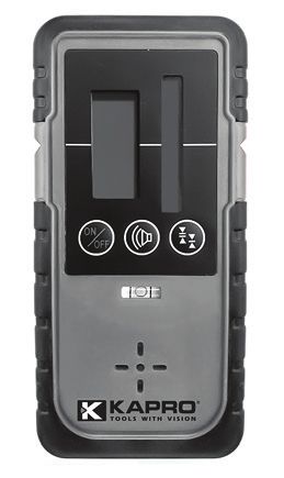
Using the Laser Detector
1. Press the On/Off button.
2. Press to select the fine or coarse detection mode (a symbol
appears on the right of the LCD, displaying which mode was
selected).
3. Select the sound or mute mode. The sound symbol
appears on the display when you select the sound option.
No symbol, indicates that you are in mute mode.
4. Turn the detection window towards the laser beam and
move the detector up and down following the direction of
the arrow on the LCD.
• Lower the Laser Detector if the arrow points down
(beeping sound).
• Raise the Laser Detector if the
arrow points up (beeping sound).
5. The level marks on the sides
of the Laser Detector are level
with the laser beam when the
horizontal beam is displayed
on the LCD (continuous sound).
1. Sound/mute mode
2. On/Off button
3. Fine adjustment button
15Using the Remote Control The laser can be operated by an infra-red remote control. The remote control will only work if there is an uninterrupted line of sight between the infra-red control and the remote control sensor, on the control panel. The effective range of the remote control is 20m. The Remote Signal Indicator flashes when a signal has been sent. 1. Remote Signal Indicator 2. Rotation speed control button 3. Scanning mode control button 4. Rotation right button 5. Rotation left button 6. Manual/Automatic mode button 7, 8. X-AXIS 9, 10. Y-AXIS 16
POWER SUPPLY
Rotary Laser
The Prolaser® Electrota™ 8991 is supplied with on-board internal
rechargeable batteries and a battery charger (AC/DC Converter).
Note: A bracket and a set of four regular type C batteries are
also supplied for optional use.
1. Recharge the batteries when the
   power indicator on the
   control panel starts to flash.
2. Plug the battery charger into a
   power source.
3. Insert the plug of the battery
   charger into the socket on the laser
   level or on the battery pack.
1. Battery charger
2. Bottom of laser
3. Rechargeable batteries
Note: You can charge the rechargeable battery pack inside or
outside of the laser level. The Rotary Laser can be operated
while recharging. It takes approximately seven hours to fully
charge the batteries. Brand new or unused rechargeable
batteries require three recharge / discharge cycles to attain full
capacity.
4. The indicator LED on the battery charger lights steady red
   while charging and steady green when fully charged. The
   indicator LED will flash if not connected to the batteries.
5. The battery pack can be removed from the Rotary Laser by
   unscrewing the locking nut, holding the battery pack in place.
Note: If the laser level is not in use for a long period of time,
remove the battery pack from the battery compartment. This will
prevent leakage or/and corrosion damage.
                                                                17
Laser Detector 1. Press the battery compartment lock and open the battery compartment cover. 2. Remove the 9V alkaline battery. 3. Replace with a new 9V alkaline battery. 4. Re-close the cover. Remote Control 1. Slide off the battery compartment cover. 2. Remove the spent batteries. 3. Replace them with two "AAA" batteries. 4. Replace the cover. External Power Supply The Prolaser® Electrota™ 8991 can use an external DC power source. This will minimize the risk of battery failure during operation. Use only the combined Battery Charger-AC/DC Converter supplied with the Rotary Laser, otherwise irreparable damage will be caused to the instrument and your warranty will be invalid. The suitable power range of the combined Battery Charger-AC/ DC Converter is 50 - 60Hz, 100VAC-240VAC. 18
CARE AND MAINTENANCE
Preventative Maintenance
• Store in a clean dry place.
• If the Rotary Laser is wet, dry off with a dry cloth.
• Do not seal the laser in the carrying case until completely dry.
• Do not attempt to dry the Rotary Laser by fire or with an electric dryer.
• Do not drop the Rotary Laser, avoid rough treatment, and avoid
  constant vibration.
• Periodically check the calibration of the Rotary Laser.
• Clean with a soft cloth, slightly dampened with a soap and water
  solution. Do not use harsh chemicals, cleaning solvents or strong
  detergents.
• Keep the laser aperture of the Rotary Laser clean by wiping it
  with a lint-free cloth moistened with isopropyl (rubbing) alcohol.
• Keep the Detection window of the Laser Detector clean by wiping
  it with a soft cloth moistened with glass cleaner.

Repairs
• See the Warranty section at the end of this manual.
• Do not take the Prolaser® Electrota™ 8991 apart or permit
  any unqualified person to take the laser level apart. Unauthorized
  servicing may cause bodily injury, irreparably damage the Rotary
  Laser and invalidate the warranty.

                                                                      19
FIELD CALIBRATION TEST The Rotary Laser leaves the factory fully calibrated. Kapro recommends that the level be checked regularly and especially after the unit has been dropped or mishandled. Horizontal Plane Calibration Test 1. Set up the Rotary Laser approximately 50m (165ft) from a wall or measuring staff. 2. Position the Rotary Laser so that the X-axis is pointing in the direction of the measuring staff or wall. 3. Turn on the Rotary Laser. 4. Mark the height of the laser beam on the wall or measuring staff (h1). 5. Rotate the Rotary Laser 180°. 6. Mark the height of the laser beam on the wall or measuring staff (h2). The difference between the heights should not exceed 10mm (3/8 inch). 7. Repeat the procedure for the Y-axis. 20
Horizontal Line Calibration Test
1.Set up the Rotary Laser on a level surface, between two walls
  or measuring staffs that are about 100ft (30m) apart.
2. Position the laser about 0.5m (1.5ft) from 1st wall/staff.
3. Position the laser on vertical leveling side.
4. Turn on the Rotary Laser, with the Plumb up/Plumb down
   projecting onto walls. Check and mark points (hA and hB) on
   both walls.
5. Reposition the laser 0.5m (1.5ft) from 2nd wall/staff, pointing in
   opposite direction. Check and mark points (hA' and hB') on
   both walls.
6. Δ1=hA-hA'
   Δ2=hB-hB'
7. The difference between Δ1 and Δ2 should be less than 6mm
   (1/4 inch).

                                                                  21
SPECIFICATIONS
Horizontal/Vertical Beam ± 0.1mm/m (0.0001"/")
Accuracy
Self Leveling Range ±5°
Waterproof / Dustproof Standard IP 65 (International
Electrotechnical Commission)
Recommended Working Indoor 50m (160 ft)
Range Outdoor 300m (980 ft) with Laser Detector
Laser Source 635 ± 5nm laser diode
Plumb down point 650 ±5nm laser diode
Classification Laser Class II
Rotational Speed (rpm) 0 (stationary point), 60,120, 300, 600 rpm
Rotational Coverage 0° (stationary point), 10°,45°, 90°,180°, 360°
(scanning function)
Setting slope ±5° (dual axis)
Effective Working -4°F —122°F (-20°C — 50°C)
Temperature
Remote Control Distance Approx. 20m
Remote Control Power Supply 2 x "AAA" batteries
Laser Power Supply DC 4.8-6V Ni-MH Rechargeable
or 4 C type alkaline
Laser Battery Life Approx. 20 hours of continuous use
Laser Detector Power Supply One 9V alkaline battery
Laser Detector Battery Life 50 hours of continuous use
Weight 2.45 kg ±0.1kg with batteries
Dimensions (LxWxH) 206(L) X 206(W) X 211(H)mm
22WARRANTY
This product is covered by a two-year limited warranty against
defects in materials and workmanship. The warranty does not
cover products that are used improperly, altered or repaired
without Kapro Tool's approval. In the event of a problem with the
laser level, please return the product to the place of purchase
with proof of purchase.
Model #8991
The serial number sticker is positioned inside the battery
compartment.
CE CONFORMITY CERTIFICATE
This product meets the standards of the Electromagnetic
Compatibility (EMC) established by the European Directive
2014/30/EU and the Low Voltage Directive (LVD) 2014/35/EU
EC DECLARATION OF CONFORMITY
We declare under our responsibility that the product 8991 is in
accordance with the requirements of the Community Directives
and Regulations:
2014/30/EU
2011/65/EU
EN60825-1: 2014
EN61326-1: 2013
23SP
Gracias por comprar el nivel láser rotativo autonivelante
Prolaser® Electrota™ 8991. Acaba de adquirir una de nuestras
herramientas innovadoras de última generación. Esta
herramienta incorpora la nueva tecnología láser que permite
tanto al usuario profesional como al particular, obtener unos
resultados precisos y ahorrar tiempo de trabajo.
APLICACIONES
El Prolaser® Electrota™ 8991 ha sido diseñado para su uso en
la mayoría de ámbitos de la construcción, por ejemplo:
• Colocación de cementos
• Construcción de muros y vallas
• Pendiente del agua y alcantarillado
• Colocación de suelos
• Suspensión de techos acústicos
• Instalación de tabiques y paneles de yeso
Pilas pilas tipo C 4
Hasta 300 m/980' recargables
165'/50m
con detector incluidas incluidas
NOTA
Conserve este manual del usuario para futura
consulta
24CONTENIDO
• Funciones 26
• Instrucciones de Seguridad 27-28
• Descripción General 29-30
• Instrucciones de Funcionamiento 31-38
Plano Horizontal (modo automático) 31
Plano Inclinado 32
Modo Manual 33
Configuración Vertical 34
Plomada 35
Función de Escaneo 36
Rotación Manual 36
Sistema de Deriva Automático 36
Detector Láser 37
Uso del Detector Láser 37
Uso del Control Remoto 38
• Fuente de Alimentación 39-40
• Cuidado y Mantenimiento 41
• Prueba de Calibración sobre el Terreno 42-43
• Especificaciones 44
• Garantía 45
25FUNCIONES
• Mecanismo electrónico autonivelante ±5°
• La rotación de 360° genera un plano horizontal o vertical
• Genera un plano inclinado de hasta ±5° en los planos X e Y
• Cinco velocidades variables (0, 60,120, 300, 600 rpm)
• Modos de escaneo crean líneas láser visibles
• Pilas recargables y convertidor de CA/CC-cargador de pilas
incluidos.
• Clasificación IP65: resistente al polvo y al agua
• Punto de plomada descendente/ascendente
• Diseño robusto con asas protectoras
• Independiente o colocado en un trípode estándar (rosca de
5/8")
• Control de remoto incluido
• Detector láser incluido
• Estuche con protección antigolpes incluido
• Incluye gafas Beamfinder® para una mejor visión del haz
láser
NOTA
Este aparato contiene componentes de
precisión sensibles a golpes externos,
impactos o caídas que pueden comprometer
su funcionalidad.- Manipular con cuidado
para mantener su exactitud.
26INSTRUCCIONES DE SEGURIDAD
ADVERTENCIA
Este producto emite radiación clasificada como clase II
según la norma EN 60825 -1
La radiación láser puede causar lesiones
oculares graves.
• No mire directamente al haz láser.
• No coloque el haz láser de modo que le pueda cegar
involuntariamente a usted u otras personas.
• No utilice el nivel láser si hay niños alrededor ni permita que
los niños utilicen el nivel láser.
• No mire un haz láser con dispositivos ópticos de aumento,
como por ejemplo, binoculares o un telescopio, ya que con
ello aumentará la gravedad de las lesiones oculares.
ADVERTENCIA: este producto contiene plomo de
soldar, y ciertas partes eléctricas indicadas por el estado de
California como causante de cáncer, defectos o daños al feto.
(Apartado 25249.6 del Código de Salud y Seguridad de
California - Proposición 65)
NOTA
Las gafas rojas especiales están destinadas
a mejorar la visibilidad del haz láser. No
protegerán sus ojos contra la radiación láser.
27• No quite ni estropee las etiquetas de advertencia sobre el
nivel láser.
• No desmonte el nivel láser.
• No deje caer el láser.
• No utilice disolventes para limpiar el láser.
• No utilice el láser en temperaturas inferiores a -20° C o
superiores a 50° C.
• No utilice el láser en atmósferas explosivas como líquidos
inflamables, gases o polvo. Las chispas de la herramienta
pueden causar ignición.
• Cuando no esté en uso, retire las pilas, bloquee el
péndulo y coloque el láser en el estuche.
• Asegúrese de que el mecanismo de bloqueo del péndulo
esté activado antes de transportar el láser.
NOTA
Si el nivel láser no se utiliza durante un período
prolongado, retire las pilas del compartimento
para evitar fugas y/o daños por corrosión.
Si el mecanismo de bloqueo del péndulo no
está activado antes del transporte, pueden
producirse daños mecánicos internos.
28DESCRIPCIÓN GENERAL
Dispositivo
1. Diodo láser.
2. Orificio de plomada.
3. Panel de control.
4. Asa de transporte.
5. Toma de cargador.
29Panel de Control
1. Rotación a la izquierda
2. Rotación a la derecha
3. Manual/Auto (en el modo manual, la autonivelación está
deshabilitada)
4. ON/OFF
5. Sistema de deriva automático
6. Control de la velocidad de rotación
7. Dirección de escáneo
8. Eje Y
9. Eje X
30INSTRUCCIONES DE FUNCIONAMIENTO
Para aprovechar al máximo de vuestro Prolaser® Electrota™ 8991,
por favor siga las siguientes instrucciones cuidadosamente.
Nota: evite instalar el láser cerca de maquinaria pesada o
fuentes de vibración que puedan afectar negativamente la
nivelación del láser.
Plano Horizontal (Modo automático)
Coloque el láser rotativo sobre una superficie seca, plana, sin
vibraciones, sobre un trípode estándar de 1,58 cm (5/8 in) (no
incluido),sobre o en cualquier soporte de pared (no incluido).
1. Configure el láser rotativo aproximadamente a nivel. El instrumento
puede compensar hasta ±5° con respecto al plano horizontal.
2. Pulse el botón de ON/OFF. El indicador de encendido se
iluminará y el haz láser parpadeará. Si el instrumento
está instalado fuera del límite de ±5°, el indicador manual
parpadeará y la rotación no comenzará.
3. Verifique que el láser rotativo esté en modo automático. El
indicador manual debe estar apagado.
4. El láser rotativo está listo para funcionar cuando el haz láser
ya no parpadea. El instrumento ahora está a nivel y el
cabezal del láser girará a 600 rpm.
5. Para hacer el haz más visible, cambie la velocidad de
rotación (consulte la página 13), cambie el modo de
escaneo (consulte la página 14) o utilice el detector láser
para detectar el haz láser (consulte la página 15).
6. Puede utilizar el control remoto para controlar el láser
rotativo (consulte la página 16). Esta opción es muy útil en la
excavación de zanjas o en la colocación de cemento.
7. Pulse el botón de ON/OFF para apagar el láser rotativo.
31Plano Inclinado
El láser rotativo se puede configurar para crear un plano
inclinado direccional simple o doble a ±5° con respecto al
plano horizontal. Esto es muy útil para colocar superficies
de cemento inclinadas, asegurando las vías de vertido, así
como también para colocar tuberías de agua y alcantarillado.
1. Configure el láser rotativo aproximadamente a nivel. El
instrumento puede compensar hasta ±5° con respecto al
plano horizontal.
2. Pulse el botón de ON/OFF. El indicador se iluminará y
el haz láser parpadeará. Si el instrumento está instalado
fuera del límite de ±5°, el indicador manual parpadeará y
la rotación no comenzará.
3. El láser rotativo está listo para funcionar cuando el haz
láser ya no parpadea. El instrumento ahora está a nivel y
el cabezal del láser
girará a 600 rpm.
4. Pulse el botón Manual/
Automático para cambiar
el láser rotativo al modo
manual.
5. Verifique que el
indicador Manual esté encendido.
6. En el caso de pendiente en dirección X:
Coloque el eje X paralelo al plano que se va a configurar
en pendiente.
32Pulse para subir X1 y bajar X2. Pulse para subir X2 y
bajar X1.
En el caso de pendiente en la dirección Y:
Coloque el eje Y paralelo al plano que se va a configurar en
pendiente.
Pulse para subir Y2 y bajar Y1. Pulse para subir Y1 y bajar
Y2.
7. Para hacer el haz más visible, cambie la velocidad de rotación
(consulte la página 13), cambie el modo de escaneo (consulte
la página 14) o utilice el detector láser para detectar el haz láser
(consulte la página 15).
8. Puede utilizar el control remoto para controlar el láser rotativo
(consulte la página 16). Esta opción es muy útil en la excavación
de zanjas o en la colocación de cemento.
9. Pulse el botón de ON/OFF para apagar el láser rotativo.
Modo Manual
Si se presiona el botón Manual/Auto y el indicador led que está al
lado está prendido, se desactiva la autonivelación y el haz láser
girará independientemente de la posición del nivel. El nivel se puede
configurar según sea necesario y se utiliza para marcar la línea en
cualquier ángulo.
33Configuración Vertical El láser rotativo se puede configurar para crear una línea de láser vertical y de este modo verificar la alineación vertical de una pared o el poste de una valla. 1. Coloque el láser rotativo de lado sobre una superficie seca, plana, sin vibraciones o sobre un trípode estándar de 5/8" (no incluido) o sobre cualquier soporte de pared (no incluido). Configure el nivel aproximado del láser rotativo. El instrumento puede compensar una variación de hasta ±5° con respecto al plano vertical. 2. Pulse el botón de ON/OFF para prender el láser rotativo. El indicador de ON se iluminará y el haz láser comenzará a parpadear. 3. Verifique que el láser rotativo esté en modo automático. El indicador manual debe estar apagado. 4. El láser rotativo está listo para funcionar cuando el haz láser ha dejado de parpadear. El instrumento ahora está a nivel y el cabezal del láser girará a 600 rpm. 5. Si el haz láser no es lo suficientemente visible, ajuste la velocidad de rotación (consulte la página 13), o utilice el detector láser para detectar el haz láser (consulte la página 15). 6. Puede utilizar el control remoto para controlar el láser rotativo (consulte la página 16). Esta opción es muy útil cuando se trabaja en altura o en andamios. 7. Pulse el botón de ON/OFF para apagar el láser rotativo. 34
Plomada
La función de Plomada le permite centrar el láser rotativo en
un punto seleccionado. Es mucho más fácil utilizar esta función
si configura el láser rotativo sobre un trípode con un perno de
conexión hueco.
1. Instale el láser rotativo sobre un trípode.
2. Mueva el trípode y el láser rotativo para que queden
   aproximadamente por encima del punto seleccionado.
3. Nivele el láser rotativo según se indica en la configuración
   horizontal.
4. Encienda el láser rotativo.
5. Mueva el haz de plomada hacia abajo sobre el punto
   seleccionado en el suelo subiendo y bajando las patas del
   trípode.
6. Nivele otra vez el láser rotativo y ajuste el haz de plomada
   con las patas del trípode como en el paso 5.
7. Repita el paso 6 hasta que el haz de plomada sea lo
   suficientemente exacto para sus objetivos.
8. Si desea transferir un punto al techo, utilice el haz de
   plomada una vez que el láser rotativo esté centrado con
   exactitud.
Cambio de la Velocidad de Rotación
El haz láser es más visible cuando la velocidad de rotación es
más lenta. Cambie la velocidad del cabezal del láser rotativo
pulsando el botón de Control de velocidad. La opción por
defecto es 600 rpm. Si pulsa el botón de Control de velocidad,
la velocidad de rotación avanza un ciclo (600 0 60 120
300 600 rpm).Para establecer una marca de nivel a largas
distancias o en condiciones de baja visibilidad, la rotación
se puede detener (velocidad = 0 rpm). El haz láser se puede
colocar con precisión utilizando los botones Rotación a la
izquierda y Rotación a la derecha.
                                                                35
Función de Escaneo La función de escaneo se utiliza para limitar el área cubierta por el haz láser, ya sea por motivos de seguridad o para mejorar la visibilidad y la sensibilidad. Un segmento de escaneo más pequeño será más visible que uno más grande. El modo por defecto es una rotación de 360°, que proporciona un haz horizontal o inclinado en toda la zona de trabajo o habitación. El botón de exploración cambia el modo de rotación de 360° a una rotación de 10° 45° 90° 180° 360°. Pulse el botón de exploración hasta que el láser se configure en el modo de escaneo deseado. La marca de escaneo se puede posicionar con exactitud usando los controles de rotación en sentido horario y en sentido antihorario. Rotación Manual Cuando el haz láser está a 0° rpm o en modo de escaneo, puede girar manualmente el haz con las teclas de Rotación a la izquierda y a la derecha. Sistema de Deriva Automático Utilice esta función para evitar la desalineación del nivel láser mientras está en modo automático. Pulse la tecla del sistema de deriva automática después de activar el nivel láser en el modo automático. El indicador led junto a esta tecla parpadeará y el sistema de deriva automático se activará. En modo automático, el nivel láser no se volverá a nivelar ni a girar después de cualquier desplazamiento. Si el nivel láser no gira y el indicador led junto a la tecla del sistema de deriva automática parpadea con más frecuencia, quiere decir que el nivel se ha desplazado mientras estaba en funcionamiento. Verifique la posición del haz láser y ajústelo, si es necesario, antes de volver a prenderlo. Desconecte el sistema de deriva automática, compruebe/reajuste la posición del dispositivo y vuelva a prenderlo. 36
Detector Láser
El Prolaser® Electrota™ 8991 es efectivo hasta 300 m (980
pies) cuando se utiliza junto con el detector láser.
Utilice el detector láser cuando sea difícil ver el haz de luz,
como por ejemplo en exteriores o en habitaciones luminosas.
Coloque el detector láser en una varilla si la unidad láser está
por encima de la altura de la cabeza.
Uso del Detector Láser
1. Pulse el botón de ON/OFF.
2. Pulse para seleccionar el modo de detección fina o gruesa
   (un símbolo que aparece a la derecha de la pantalla LCD y
   que muestra el modo seleccionado).
3. Seleccione el modo de sonido o mudo. El símbolo del
   sonido aparece en la pantalla cuando selecciona la opción
   de sonido. Si no hay símbolo, significa que está en modo mudo.
4. Gire la ventana de detección hacia el haz láser y mueva el
   detector hacia arriba y hacia abajo siguiendo la dirección de
   la flecha en la pantalla LCD.
• Baje el detector láser si la flecha apunta hacia abajo (se
   escuchará un pitido).
• Levante el detector láser si la
      flecha apunta hacia arriba (se
   escuchará un pitido).
5. Las marcas de nivel en los lados
   del detector láser están a nivel
   con el haz láser cuando el haz
   horizontal se muestra en la
   pantalla LCD (sonido continuo).
1. Modo de sonido/silencio
2. Botón de ON/OFF
3. Botón de ajuste fino
                                                                37
Uso del Control Remoto El láser puede funcionar mediante un control remoto de infrarrojos. El control remoto solo funcionará si hay una línea de visión ininterrumpida entre el control de infrarrojos y el sensor de control remoto en el panel de control. El alcance efectivo del control remoto es de 20m. El indicador de señal remota parpadea cuando se envía una señal. 1. Indicador de señal remota 2. Botón de control de la velocidad de rotación 3. Botón de control del modo de escaneo 4. Botón de rotación a la derecha 5. Botón de rotación a la izquierda 6. Botón de modo Manual/Automático 7, 8. Eje X 9, 10. Eje Y 38
FUENTE DE ALIMENTACIÓN
Láser Rotativo
El Prolaser® Electrota™ 8991 se suministra con pilas internas
recargables y un cargador de pilas (convertidor de CA/CC).
Nota: también se suministran un
soporte y un conjunto de cuatro pilas
tipo C normales para uso opcional.
1. Recargue las pilas cuando el
   indicador de alimentación en el panel
   de control comience a parpadear.
2. Conecte el cargador de pila a
   una fuente de alimentación.
3. Introduzca el enchufe del
   cargador en la toma del nivel
   láser o en el paquete de pilas.
1. Cargador de pila
2. Parte inferior del láser
3. Pilas recargables
Nota: puede cargar el paquete de pilas recargables dentro o
fuera del nivel láser. El láser rotativo puede funcionar mientras
se está cargando. Las pilas tardan unas siete horas en
recargarse por completo. Las pilas nuevas o recargables -sin
uso- necesitan tres ciclos de carga/descarga para alcanzar la
máxima capacidad.
4. El indicador led en el cargador de pila se ilumina en rojo
    mientras está cargando y en verde cuando está completamente
    cargado. El indicador LED parpadeará si no está conectado a
    las pilas.
5. Para sacar el paquete de pilas del láser rotativo desatornille
   la tuerca de bloqueo y sujete el paquete de pilas en posición.
Nota: si no usa el nivel láser durante un período prolongado,
retire el paquete de pilas del compartimento. Así evitará fugas
y/o daños por corrosión.
                                                               39
Detector Láser 1. Pulse el bloqueo del compartimento de pilas y abra la tapa. 2. Retire la pila alcalina de 9 V. 3. Sustitúyala por una pila alcalina de 9 V nueva. 4. Vuelva a cerrar la tapa. Control remoto 1. Deslice la tapa del compartimento de pilas. 2. Retire las pilas gastadas. 3. Sustitúyalas por dos pilas “AAA". 4. Vuelva a colocar la tapa. Fuente de Alimentación Externa El Prolaser® Electrota™ 8991 puede usar una fuente de alimentación de CC externa. De este modo se minimiza el riesgo de fallo de la pila durante el funcionamiento. Utilice solo el convertidor de CA/CC-cargador de pila suministrado con el láser rotativo. En caso contrario, se producirán daños irreparables en el instrumento y su garantía no será válida. El intervalo de potencia adecuado del convertidor de CA/CC-cargador de pila combinado es de 50 – 60 Hz, 100 V AC-240 V AC. 40
CUIDADO Y MANTENIMIENTO
Mantenimiento Preventivo
• Guarde el láser en un lugar limpio y seco.
• Si el láser rotativo está mojado, séquelo con un paño seco.
• No cierre el láser en el estuche hasta que esté completamente seco.
• No intente secar el láser rotativo con fuego ni con un secador
  eléctrico.
• No deje caer el láser rotativo, evite manipularlo de forma brusca
  y evite las vibraciones constantes.
• Compruebe periódicamente la calibración del láser rotativo.
• Límpielo con un paño suave, humedecido ligeramente con una
  solución de jabón y agua. No utilice productos químicos agresivos,
  ni disolventes de limpieza o detergentes fuertes.
• Mantenga limpia la abertura del láser rotativo limpiándola con un
  paño (que no deja pelusa) humedecido , humedecido con alcohol
  isopropílico (frotando).
• Mantenga limpia la ventana de detección del detector láser
   limpiándola con un paño suave, humedecido con limpiador de
   vidrio.
Reparaciones
• Consulte la sección de Garantía al final de este manual.
• No desmonte el Prolaser® Electrota™ 8991 ni permita que
  personas no cualificadas desmonten el nivel láser. La reparación
  por parte de un servicio no autorizado, puede causar lesiones
  corporales, daños irreparables en el láser rotativo e invalidar la
  garantía.
                                                                 41
PRUEBA DE CALIBRACIÓN
SOBRE EL TERRENO
El láser rotativo sale de fábrica totalmente calibrado. Kapro
recomienda que se compruebe el nivel regularmente y
especialmente después de que la unidad se haya caído o
manipulado incorrectamente.
Prueba de Calibración de Plano Horizontal
1. Instale el láser rotativo a aproximadamente 50 m (165 pies)
de una pared o escala de medida.
2. Coloque el láser rotativo de modo que el eje X apunte en la
dirección de la pared o escala de medida.
3. Encienda el láser rotativo.
4. Marque la altura del haz láser en la pared o escala de medida
(h1).
5. Gire el láser rotativo 180°.
6. Marque la altura del haz láser sobre la pared o escala de medida
(h 2). La diferencia entre las alturas no debe exceder 10 mm
(3/8 pulgadas).
7. Repita el procedimiento para el eje Y.
aprox 50 m aprox 50 m
42Prueba de Calibración de Línea Horizontal
1. Instale el láser rotativo en una superficie a nivel, entre
dos paredes o escalas de medida que estén separadas
aproximadamente 30 m.
2. Coloque el láser aproximadamente 0,5 m (1,5 pies) de la
primera pared/escala de medida.
3. Coloque el láser en el lado de nivelación vertical.
4. Encienda el láser rotativo con la plomada proyectando hacia
arriba/hacia abajo sobre las paredes. Compruebe y marque los
puntos (hA y hB) en ambas paredes.
5. Vuelva a colocar el láser a 0,5m de la segunda pared/escala
de medida apuntando en la dirección contraria. Compruebe y
marque los puntos (hA’ y hB’) sobre ambas paredes.
6. Δ1=hA-hA' Δ2=hB-hB'
7. La diferencia entre Δ1 y Δ2 debe ser inferior a 6 mm
aproximadamente 30 m aproximadamente 30 m
Pared 1 Pared 2 Pared 1 Pared 2
43ESPECIFICACIONES
Precisión del haz horizontal/ ± 0.1mm/m (0.0001"/")
vertical
Alcance de autonivelación ±5°
Norma de impermeabilidad/ IP 65
antipolvo (Comisión Electrotécnica Internacional)
Rango de trabajo 50 m en interiores
recomendado 300 m en exteriores con el detector láser
Fuente láser Diodo láser de 635 ±5 nm
Punto de plomada Diodo láser de 650 ±5 nm
Clasificación del láser Clase II
Velocidad de rotación (rpm) 0 (punto estacionario), 60, 120, 300, 600 rpm
Cobertura de rotación 0° (punto estacionario), 10°, 45°, 90°, 180°,
(función de escaneo) 360°
Pendiente de ajuste ±5° (doble eje)
Temperatura de trabajo eficaz -20°C — 50°C (-4°F —122°F)
Distancia del control remoto Aprox. 20 m
Fuente de alimentación del 2 baterías "AAA"
control remoto
Fuente de alimentación del Batería recargable de Ni-MH 4,8-6V CC o 4
láser pilas alcalinas tipo C
Duración de la pila del láser Aprox. 20 horas de uso continuo
Fuente de alimentación del Una pila alcalina de 9 V
detector láser
Duración de la pila del detector 50 horas de uso continuo
láser
Peso 2,45 kg ±0,1 kg con las pilas
Dimensiones (LxWxH) 206(L) X 206(A) X 211(A)mm
44GARANTÍA
Este producto está cubierto por una garantía limitada de dos
años contra defectos de materiales y mano de obra.
No cubre los productos que se utilicen inadecuadamente, se
modifiquen o se reparen sin la aprobación de Kapro.
En caso de problemas con el nivel láser que ha adquirido, por
favor devuelva el producto al lugar de compra presentando el
comprobante de compra.
Modelo #8991
La etiqueta con el número de serie está colocada en el interior
del compartimiento de pilas.
CERTIFICADO DE CONFORMIDAD CE
Este producto cumple con las normas de Compatibilidad
Electromagnética (CEM) establecido por la Directiva Europea
2014/30/EU y el Reglamento para baja tensión 2014/35/EU.
DECLARACIÓN DE CONFORMIDAD CE
Declaramos bajo nuestra responsabilidad, que el producto:
8991 está en acuerdo con los requisitos de las directivas y
reglamentos siguientes:
2014/30/EU
2011/65/EU
EN60825-1: 2014
EN61326-1: 2013
45FR
Merci d'avoir acheté le niveau laser rotatif autonivelant Prolaser®
Electrota™ 8991. Vous venez d'acquérir un de nos outils de
pointe. Cet outil intègre la dernière technologie laser permettant
au professionnel et à l'adepte du bricolage d'atteindre des
résultats précis tout en gagnant un temps précieux.
APPLICATIONS
Le Prolaser® Electrota™ 8991 est conçu pour être utilisé dans
la plupart des domaines de la construction, par exemple :
• Pose de fondations
• Construction de murs et de palissades
• Pose de conduites inclinées d'eau et d'évacuation
• Pose de sol
• Mise en place de plafonds acoustiques
• Installation de séparations et de cloisons sèches
Piles 4x type C
Jusqu'à 300 m/980' rechargeables
165'/50m
avec détecteur incluses comprises
REMARQUE
Conservez ce manuel pour référence future.
46TABLE DES MATIÈRES
• Caractéristiques 48
• Consignes de sécurité 49-50
• Présentation 51-52
• Mode d'emploi 53-60
Plan Horizontal (mode automatique) 53
Plan Incliné 54
Mode Manuel 55
Configuration Verticale 56
Projection de Haut en Bas 57
Fonction de Balayage 58
Rotation Manuelle 58
Système de Mouvement Automatique 58
Détecteur Laser 59
Utilisation du Détecteur Laser 59
Utilisation de la Commande à Distance 60
• Alimentation 61-62
• Soins et Maintenance 63
• Essai d'Étalonnage sur le Terrain 64-65
• Spécifications 66
• Garantie 67
47CARACTÉRISTIQUES
• Mécanisme électronique autonivelant sur les pentes de ±5°
• Formation du plan horizontal ou vertical par rotation à 360°
• Plan incliné jusqu'à ±5° sur l'axe des abscisses et des ordonnées
• Cinq vitesses variables (0, 60,120, 300, 600 tr/min)
• Les modes de balayage créent des lignes laser visibles
• Piles rechargeables et chargeur-convertisseur CA/CC
fournis
• Protection IP-65 contre la poussière et l'eau
• Point de projection de la verticale de haut en bas/de bas en haut
• Conception robuste avec poignées de protection.
• Structure indépendante ou fixation sur trépied standard
(filetage 5/8")
• Commande à distance incluse
• Détecteur laser inclus
• Housse de protection contre les coups incluse
• Lunettes Beamfinder® d'amélioration du faisceau laser
incluses
REMARQUE
Cet appareil contient des composants de
précision sensibles aux chocs extérieurs,
aux coups ou aux chutes qui pourraient
compromettre ses prestations. Veuillez le
manipuler avec soin pour assurer sa précision.
48CONSIGNES DE SÉCURITÉ
AVERTISSEMENT
AVERTISSEMENT
Ce produit émet des rayonnements
de classe II selon la norme EN 60825 -1
Les rayonnements laser peuvent provoquer de
graves blessures aux yeux.
• Ne regardez pas directement dans le faisceau laser.
• Ne placez pas le faisceau laser de sorte qu'il puisse vous
aveugler, ou aveugler d'autres personnes, accidentellement.
• Ne manipulez pas le niveau laser à proximité d'enfants et ne
laissez pas les enfants manipuler le niveau laser.
• Ne regardez pas le faisceau laser à l'aide de dispositifs
optiques grossissants de type télescope, car cela augmente le
risque de blessure à l'œil.
AVERTISSEMENT: ce produit du contient du plomb dans
les soudures et certaines parties électriques contiennent
des produits chimiques reconnues dans l'État de Californie
comme pouvant causer le cancer, des malformations à la
naissance ou d'autres troubles de l'appareil reproducteur
(Code de santé et de sécurité de la Californie, Section
25249.6- Proposition 65).
REMARQUE
Les lunettes rouges sont conçues pour
améliorer la visibilité du faisceau laser.
Elles ne protègent pas vos yeux contre les
rayonnements laser.
49• Ne retirez pas et ne détériorez pas les étiquettes
d'avertissement collées sur le niveau laser.
• Ne démontez pas le niveau laser.
• Ne faites pas tomber le laser.
• N'utilisez pas de solvants pour nettoyer le laser.
• N'utilisez pas le laser à des températures inférieures à -20° C
ou supérieures à 50° C
• Ne manipulez pas le laser dans des atmosphères
explosives, par exemple en présence de liquides, de gaz ou
de poussières inflammables. Les étincelles de l'outil peuvent
provoquer l'inflammation.
• Lorsqu'il n'est pas utilisé, retirez les piles, enclenchez le
verrouillage et rangez le laser dans sa housse de protection.
• Assurez-vous que le mécanisme de verrouillage est
enclenché avant de transporter le laser.
REMARQUE
Si le niveau laser n'est pas utilisé pendant une
longue période, retirez les piles du logement
prévu à cet effet afin d'éviter les fuites et/ou
la corrosion. Si le mécanisme de verrouillage
n'est pas enclenché avant le transport, cela
peut provoquer du dommage mécanique
interne
50PRÉSENTATION
Corps Principal
1. Diode laser
2. Voyant de la projection de bas en haut
3. Panneau de commande
4. Poignée de transport
5. Prise du chargeur
51Panneau de Commande 1. Rotation gauche 2. Rotation droite 3. Manuel/Auto (système autonivelant désactivé en mode manuel) 4. Alimentation On/Off 5. Système de mouvement automatique 6. Commande de vitesse de la rotation 7. Sens du balayage 8. Axe ordonnées 9. Axe des abscisses 52
MODE D'EMPLOI
Pour tirer le maximum de profit de votre Prolaser® Electrota™
8991, veuillez lire attentivement les instructions suivantes.
Remarque: Éviter d'installer le laser à proximité d'équipements
lourds ou de sources de vibration pouvant nuire aux
performances du laser.
Plan Horizontal (mode automatique)
Placez le laser rotatif sur une surface sèche, plate et sans
vibrations ou sur un trépied 5/8" standard (pas inclus) ou sur
une perche de nivellement plafond/sol (pas incluse) ou sur
quelconque accessoire de montage mural (pas inclus).
1. Installez le laser rotatif au niveau approximatif ; l'outil peut
   compenser jusqu'à ±5° à partir du plan horizontal.
2. Appuyez sur le bouton On/Off l'indicateur d'alimentation
    s'allume et le faisceau laser clignote. Si l'appareil est configuré
    en dehors de la tolérance de ±5°, l'indicateur manuel
    clignote et la rotation ne démarre pas.
3. Vérifiez que le laser rotatif est en mode automatique ;
   l'indicateur manuel doit être éteint.
4. Le laser rotatif est prêt à fonctionner lorsque le faisceau ne
   clignote plus. L'outil est désormais à niveau et la tête du
   laser tourne à 600 tr/min.
5. Pour mieux voir le faisceau, changez la vitesse de rotation
   (page 13), changez le mode de balayage (page 14) ou utilisez
   le détecteur laser pour détecter le faisceau laser (page 15).
6. Vous pouvez utiliser la commande à distance pour contrôler
   le laser rotatif (page 16). Cette option est particulièrement
   utile pour les travaux de tranchée ou de pose de béton.
7. Pour éteindre le laser rotatif, appuyez sur le bouton On/Off.
                                                                    53
Plan Incliné
Le laser rotatif peut être configuré de sorte à créer une
projection simple ou double à partir du plan horizontal, avec
une tolérance de ±5°. Cela est très utile pour la pose de
surfaces inclinées en béton, pour s'assurer des voies de
ruissellement et poser des conduites d'eau et d'égout.
1. Installez le laser rotatif au niveau approximatif ; l'outil peut
compenser jusqu'à ±5° à partir du plan horizontal.
2. Appuyez sur le bouton On/Off. L'indicateur d'alimentation
s'allume et le faisceau laser clignote. Si l'appareil est
configuré en dehors de la tolérance de ±5°, l'indicateur
manuel clignote et la rotation ne démarre pas.
3. Le laser rotatif est prêt à fonctionner lorsque le faisceau ne
clignote plus. L'outil est désormais à niveau et la tête du
laser tourne à 600 tr/min.
4. Appuyez sur le bouton
Manuel/Automatique
pour basculer le laser
rotatif au mode manuel.
5. Assurez-vous que
l'indicateur du mode
manuel est allumé.
6. Pente sur l'axe des abscisses :
Pour positionner l'axe des abscisses parallèle au
plan, vous devez configurer la pente. Appuyez sur
pour augmenter X1 et baisser X2. Appuyez sur pour
augmenter X2 et baisser X1.
54Pente sur l'axe des ordonnées :
Pour positionner l'axe des ordonnées parallèle au plan, vous
devez configurer la pente.
Appuyez sur pour augmenter Y2 et baisser Y1. Appuyez sur
pour augmenter Y1 et baisser Y2.
7. Pour mieux voir le faisceau, changez la vitesse de rotation (page
13), changez le mode de balayage (page 14) ou utilisez le
détecteur laser pour détecter le faisceau laser (page 15).
8. Vous pouvez utiliser la commande à distance pour contrôler le
laser rotatif (page 16). Cette option est particulièrement utile pour
les travaux de tranchée ou de pose de béton.
9. Pour éteindre le laser rotatif, appuyez sur le bouton On/Off.
Mode Manuel
Appuyez sur le bouton Manuel/Auto (le voyant LED se trouvant à
côté est allumé) pour désactiver le système autonivelant ; le faisceau
laser se met à tourner quelle que soit la position du niveau. Le
niveau peut être configuré selon les besoins et utilisé pour marquer
la ligne quel que soit l'angle.
55You can also read