Enterprise Capacity 3.5 HDD - Seagate
←
→
Page content transcription
If your browser does not render page correctly, please read the page content below
Enterprise Capacity
     3.5 HDD
            v6 SATA Product Manual

  Standard 4KN models      Standard 512E models
    ST10000NM0146              ST10000NM0086
     ST8000NM0136              ST8000NM0206

    Self-Encryption            Self-Encryption
     4KN models                 512E models
    ST10000NM0166              ST10000NM0156

    SED FIPS 140-2             SED FIPS 140-2
     4KN models                 512E models
    ST10000NM0186              ST10000NM0176

                100803343, Rev. D
               Gen 6 - February 2018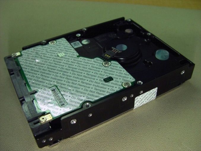
Document Revision History
      Revision                 Date          Pages affected and Description of changes

        Rev. A             06/17/2016 Initial release.

                                      7: Updated temperature row header to “Drive case temperature”
        Rev. B             11/14/2016 18: Added MSIP Korean text for Class B device warning
                                      19: Updated to China RoHS 2

        Rev. C             04/12/2017
                                             10: Changed 12V tolerance to ± 10%
                                             15: Removed following text (8TB and 6TB models)

                           02/12/2018 17-20: Updated Section 2.10 through 2.11.4 per Compliance Council
        Rev. D                        23: Updated fastener penetration depth to 0.14” in text & mechanical drawing

© 2018 Seagate Technology LLC. All rights reserved.
Publication number: 100803343, Rev. D February 2018
Seagate, Seagate Technology and the Spiral logo are registered trademarks of Seagate Technology LLC in the United States and/or other countries. PowerChoice and SeaTools are either
trademarks or registered trademarks of Seagate Technology LLC or one of its affiliated companies in the United States and/or other countries. The FIPS logo is a certification mark of
NIST, which does not imply product endorsement by NIST, the U.S., or Canadian governments. All other trademarks or registered trademarks are the property of their respective owners.
No part of this publication may be reproduced in any form without written permission of Seagate Technology LLC.
Call 877-PUB-TEK1 (877-782-8351) to request permission.
When referring to drive capacity, one gigabyte, or GB, equals one billion bytes and one terabyte, or TB, equals one trillion bytes. Your computer’s operating system may use a different
standard of measurement and report a lower capacity. In addition, some of the listed capacity is used for formatting and other functions, and thus will not be available for data storage.
Actual quantities will vary based on various factors, including file size, file format, features and application software. Actual data rates may vary depending on operating environment
and other factors. The export or re-export of hardware or software containing encryption may be regulated by the U.S. Department of Commerce, Bureau of Industry and Security (for
more information, visit www.bis.doc.gov), and controlled for import and use outside of the U.S. Seagate reserves the right to change, without notice, product offerings or specifications.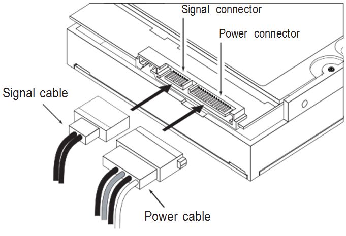
Contents

Seagate® Technology Support Services . . . . . . . . . . . . . . . . . . . . . . . . . . . . . . . . . . . . . . . . . . . . . . . . . . . . . . . . . . . . . . . 4

1.0         Introduction . . . . . . . . . . . . . . . . . . . . . . . . . . . . . . . . . . . . . . . . . . . . . . . . . . . . . . . . . . . . . . . . . . . . . . . . . . . . . . . . . 5
            1.1     About the Serial ATA interface . . . . . . . . . . . . . . . . . . . . . . . . . . . . . . . . . . . . . . . . . . . . . . . . . . . . . . . . . . . . . . . . 6

2.0         Drive specifications . . . . . . . . . . . . . . . . . . . . . . . . . . . . . . . . . . . . . . . . . . . . . . . . . . . . . . . . . . . . . . . . . . . . . . . . . . 7
            2.1     Formatted capacity . . . . . . . . . . . . . . . . . . . . . . . . . . . . . . . . . . . . . . . . . . . . . . . . . . . . . . . . . . . . . . . . . . . . . . . . . . 9
                    2.1.1       LBA mode. . . . . . . . . . . . . . . . . . . . . . . . . . . . . . . . . . . . . . . . . . . . . . . . . . . . . . . . . . . . . . . . . . . . . . . . . . 9
            2.2     Recording and interface technology . . . . . . . . . . . . . . . . . . . . . . . . . . . . . . . . . . . . . . . . . . . . . . . . . . . . . . . . . . 9
            2.3     Start/stop times . . . . . . . . . . . . . . . . . . . . . . . . . . . . . . . . . . . . . . . . . . . . . . . . . . . . . . . . . . . . . . . . . . . . . . . . . . . . . . 9
            2.4     Power specifications . . . . . . . . . . . . . . . . . . . . . . . . . . . . . . . . . . . . . . . . . . . . . . . . . . . . . . . . . . . . . . . . . . . . . . . . . 10
                    2.4.1       Power consumption . . . . . . . . . . . . . . . . . . . . . . . . . . . . . . . . . . . . . . . . . . . . . . . . . . . . . . . . . . . . . . . 10
                    2.4.2       Conducted noise . . . . . . . . . . . . . . . . . . . . . . . . . . . . . . . . . . . . . . . . . . . . . . . . . . . . . . . . . . . . . . . . . . 11
                    2.4.3       Voltage tolerance . . . . . . . . . . . . . . . . . . . . . . . . . . . . . . . . . . . . . . . . . . . . . . . . . . . . . . . . . . . . . . . . . 11
                    2.4.4       Extended Power Conditions - PowerChoiceTM . . . . . . . . . . . . . . . . . . . . . . . . . . . . . . . . . . . . . 12
            2.5     Environmental limits. . . . . . . . . . . . . . . . . . . . . . . . . . . . . . . . . . . . . . . . . . . . . . . . . . . . . . . . . . . . . . . . . . . . . . . . . 14
                    2.5.1       Temperature . . . . . . . . . . . . . . . . . . . . . . . . . . . . . . . . . . . . . . . . . . . . . . . . . . . . . . . . . . . . . . . . . . . . . . 14
                    2.5.2       Humidity. . . . . . . . . . . . . . . . . . . . . . . . . . . . . . . . . . . . . . . . . . . . . . . . . . . . . . . . . . . . . . . . . . . . . . . . . . 14
                    2.5.3       Effective Altitude (sea level) . . . . . . . . . . . . . . . . . . . . . . . . . . . . . . . . . . . . . . . . . . . . . . . . . . . . . . . 14
                    2.5.4       Shock . . . . . . . . . . . . . . . . . . . . . . . . . . . . . . . . . . . . . . . . . . . . . . . . . . . . . . . . . . . . . . . . . . . . . . . . . . . . . 15
                    2.5.5       Vibration. . . . . . . . . . . . . . . . . . . . . . . . . . . . . . . . . . . . . . . . . . . . . . . . . . . . . . . . . . . . . . . . . . . . . . . . . . 15
            2.6     Acoustics. . . . . . . . . . . . . . . . . . . . . . . . . . . . . . . . . . . . . . . . . . . . . . . . . . . . . . . . . . . . . . . . . . . . . . . . . . . . . . . . . . . . 16
            2.7     Test for Prominent Discrete Tones (PDTs) . . . . . . . . . . . . . . . . . . . . . . . . . . . . . . . . . . . . . . . . . . . . . . . . . . . . . 16
            2.8     Electromagnetic immunity. . . . . . . . . . . . . . . . . . . . . . . . . . . . . . . . . . . . . . . . . . . . . . . . . . . . . . . . . . . . . . . . . . . 16
            2.9     Reliability . . . . . . . . . . . . . . . . . . . . . . . . . . . . . . . . . . . . . . . . . . . . . . . . . . . . . . . . . . . . . . . . . . . . . . . . . . . . . . . . . . . 17
                    2.9.1       Annualized Failure Rate (AFR) and Mean Time Between Failures (MTBF) . . . . . . . . . . . . . 17
            2.10    Agency and Safety Certifications . . . . . . . . . . . . . . . . . . . . . . . . . . . . . . . . . . . . . . . . . . . . . . . . . . . . . . . . . . . . . 17
                    2.10.1      Safety certification . . . . . . . . . . . . . . . . . . . . . . . . . . . . . . . . . . . . . . . . . . . . . . . . . . . . . . . . . . . . . . . . 17
                    2.10.2      European Union (EU) CE Marking Requirements . . . . . . . . . . . . . . . . . . . . . . . . . . . . . . . . . . . . 17
                    2.10.3      Australian RCM Compliance Mark . . . . . . . . . . . . . . . . . . . . . . . . . . . . . . . . . . . . . . . . . . . . . . . . . . 17
                    2.10.4      Canada ICES-003 . . . . . . . . . . . . . . . . . . . . . . . . . . . . . . . . . . . . . . . . . . . . . . . . . . . . . . . . . . . . . . . . . . 18
                    2.10.5      South Korean KC Certification Mark . . . . . . . . . . . . . . . . . . . . . . . . . . . . . . . . . . . . . . . . . . . . . . . . 18
                    2.10.6      Morocco Commodity Mark . . . . . . . . . . . . . . . . . . . . . . . . . . . . . . . . . . . . . . . . . . . . . . . . . . . . . . . . 18
                    2.10.7      Taiwanese BSMI . . . . . . . . . . . . . . . . . . . . . . . . . . . . . . . . . . . . . . . . . . . . . . . . . . . . . . . . . . . . . . . . . . . 18
                    2.10.8      FCC verification . . . . . . . . . . . . . . . . . . . . . . . . . . . . . . . . . . . . . . . . . . . . . . . . . . . . . . . . . . . . . . . . . . . 18
            2.11    Environmental protection. . . . . . . . . . . . . . . . . . . . . . . . . . . . . . . . . . . . . . . . . . . . . . . . . . . . . . . . . . . . . . . . . . . . 19
                    2.11.1      European Union Restriction of Hazardous Substance Law. . . . . . . . . . . . . . . . . . . . . . . . . . . 19
                    2.11.2      Restriction of Hazardous Substances in Electrical and Electronic Equipment . . . . . . . . . 19
                    2.11.3      China Requirements —China RoHS 2 . . . . . . . . . . . . . . . . . . . . . . . . . . . . . . . . . . . . . . . . . . . . . . 19
                    2.11.4      Taiwan Requirements — Taiwan RoHS . . . . . . . . . . . . . . . . . . . . . . . . . . . . . . . . . . . . . . . . . . . . . 20
            2.12    Corrosive environment . . . . . . . . . . . . . . . . . . . . . . . . . . . . . . . . . . . . . . . . . . . . . . . . . . . . . . . . . . . . . . . . . . . . . . 20
            2.13    Reference documents . . . . . . . . . . . . . . . . . . . . . . . . . . . . . . . . . . . . . . . . . . . . . . . . . . . . . . . . . . . . . . . . . . . . . . . 21
            2.14    Product warranty . . . . . . . . . . . . . . . . . . . . . . . . . . . . . . . . . . . . . . . . . . . . . . . . . . . . . . . . . . . . . . . . . . . . . . . . . . . . 21

Seagate Enterprise Capacity 3.5 HDD v6 Serial ATA Product Manual, Rev. D                                                                                                                                   2
Contents
3.0 Configuring and mounting the drive . . . . . . . . . . . . . . . . . . . . . . . . . . . . . . . . . . . . . . . . . . . . . . . . . . . . . . . . . 22
3.1 Handling and static-discharge precautions . . . . . . . . . . . . . . . . . . . . . . . . . . . . . . . . . . . . . . . . . . . . . . . . . . . 22
3.2 Configuring the drive . . . . . . . . . . . . . . . . . . . . . . . . . . . . . . . . . . . . . . . . . . . . . . . . . . . . . . . . . . . . . . . . . . . . . . . . 22
3.3 Serial ATA cables and connectors . . . . . . . . . . . . . . . . . . . . . . . . . . . . . . . . . . . . . . . . . . . . . . . . . . . . . . . . . . . . 22
3.4 Drive mounting . . . . . . . . . . . . . . . . . . . . . . . . . . . . . . . . . . . . . . . . . . . . . . . . . . . . . . . . . . . . . . . . . . . . . . . . . . . . . 23
3.4.1 Mechanical specifications . . . . . . . . . . . . . . . . . . . . . . . . . . . . . . . . . . . . . . . . . . . . . . . . . . . . . . . . . 23
4.0 About FIPS. . . . . . . . . . . . . . . . . . . . . . . . . . . . . . . . . . . . . . . . . . . . . . . . . . . . . . . . . . . . . . . . . . . . . . . . . . . . . . . . . . 24
5.0 About self-encrypting drives. . . . . . . . . . . . . . . . . . . . . . . . . . . . . . . . . . . . . . . . . . . . . . . . . . . . . . . . . . . . . . . . . 25
5.1 Data encryption . . . . . . . . . . . . . . . . . . . . . . . . . . . . . . . . . . . . . . . . . . . . . . . . . . . . . . . . . . . . . . . . . . . . . . . . . . . . . 25
5.2 Controlled access. . . . . . . . . . . . . . . . . . . . . . . . . . . . . . . . . . . . . . . . . . . . . . . . . . . . . . . . . . . . . . . . . . . . . . . . . . . . 25
5.2.1 Admin SP . . . . . . . . . . . . . . . . . . . . . . . . . . . . . . . . . . . . . . . . . . . . . . . . . . . . . . . . . . . . . . . . . . . . . . . . . 25
5.2.2 Locking SP . . . . . . . . . . . . . . . . . . . . . . . . . . . . . . . . . . . . . . . . . . . . . . . . . . . . . . . . . . . . . . . . . . . . . . . . 25
5.2.3 Default password . . . . . . . . . . . . . . . . . . . . . . . . . . . . . . . . . . . . . . . . . . . . . . . . . . . . . . . . . . . . . . . . . 25
5.3 Random number generator (RNG). . . . . . . . . . . . . . . . . . . . . . . . . . . . . . . . . . . . . . . . . . . . . . . . . . . . . . . . . . . . 26
5.4 Drive locking . . . . . . . . . . . . . . . . . . . . . . . . . . . . . . . . . . . . . . . . . . . . . . . . . . . . . . . . . . . . . . . . . . . . . . . . . . . . . . . . 26
5.5 Data bands . . . . . . . . . . . . . . . . . . . . . . . . . . . . . . . . . . . . . . . . . . . . . . . . . . . . . . . . . . . . . . . . . . . . . . . . . . . . . . . . . . 26
5.6 Cryptographic erase . . . . . . . . . . . . . . . . . . . . . . . . . . . . . . . . . . . . . . . . . . . . . . . . . . . . . . . . . . . . . . . . . . . . . . . . . 26
5.7 Authenticated firmware download . . . . . . . . . . . . . . . . . . . . . . . . . . . . . . . . . . . . . . . . . . . . . . . . . . . . . . . . . . . 26
5.8 Power requirements . . . . . . . . . . . . . . . . . . . . . . . . . . . . . . . . . . . . . . . . . . . . . . . . . . . . . . . . . . . . . . . . . . . . . . . . . 27
5.9 Supported commands . . . . . . . . . . . . . . . . . . . . . . . . . . . . . . . . . . . . . . . . . . . . . . . . . . . . . . . . . . . . . . . . . . . . . . . 27
5.10 RevertSP . . . . . . . . . . . . . . . . . . . . . . . . . . . . . . . . . . . . . . . . . . . . . . . . . . . . . . . . . . . . . . . . . . . . . . . . . . . . . . . . . . . . 27
5.11 ATA Security Erase Unit Command on SED SATA drives . . . . . . . . . . . . . . . . . . . . . . . . . . . . . . . . . . . . . . . 27
5.12 Sanitize Device - CRYPTO SCRAMBLE EXT . . . . . . . . . . . . . . . . . . . . . . . . . . . . . . . . . . . . . . . . . . . . . . . . . . . . . 27
6.0 Serial ATA (SATA) interface . . . . . . . . . . . . . . . . . . . . . . . . . . . . . . . . . . . . . . . . . . . . . . . . . . . . . . . . . . . . . . . . . . 28
6.1 Hot-Plug compatibility. . . . . . . . . . . . . . . . . . . . . . . . . . . . . . . . . . . . . . . . . . . . . . . . . . . . . . . . . . . . . . . . . . . . . . . 28
6.2 Serial ATA device plug connector pin definitions . . . . . . . . . . . . . . . . . . . . . . . . . . . . . . . . . . . . . . . . . . . . . 28
6.3 Supported ATA commands . . . . . . . . . . . . . . . . . . . . . . . . . . . . . . . . . . . . . . . . . . . . . . . . . . . . . . . . . . . . . . . . . . 29
6.3.1 Identify Device command . . . . . . . . . . . . . . . . . . . . . . . . . . . . . . . . . . . . . . . . . . . . . . . . . . . . . . . . . 31
6.3.2 Set Features command . . . . . . . . . . . . . . . . . . . . . . . . . . . . . . . . . . . . . . . . . . . . . . . . . . . . . . . . . . . . 34
6.3.3 S.M.A.R.T. commands. . . . . . . . . . . . . . . . . . . . . . . . . . . . . . . . . . . . . . . . . . . . . . . . . . . . . . . . . . . . . . 35
Seagate Enterprise Capacity 3.5 HDD v6 Serial ATA Product Manual, Rev. D 3Seagate® Technology Support Services For information regarding online support and services, visit: http://www.seagate.com/contacts/ For information regarding Warranty Support, visit: http://www.seagate.com/support/warranty-and-replacements/ For information regarding data recovery services, visit: http://www.seagate.com/services-software/recover/ For Seagate OEM, Distribution partner and reseller portals, visit: http://www.seagate.com/partners/ Seagate Enterprise Capacity 3.5 HDD v6 Serial ATA Product Manual, Rev. D 4
1.0        Introduction
This manual describes the functional, mechanical and interface specifications for the following:
Seagate® Enterprise Capacity 3.5 HDD v6 Serial ATA model drives:.

                                   512E models
      Standard               Self-Encrypting (SED)             SED FIPS (140-2)
    ST10000NM0086               ST10000NM0156                  ST10000NM0176
    ST8000NM0206

                                   4KN models
      Standard               Self-Encrypting (SED)             SED FIPS (140-2)
    ST10000NM0146               ST10000NM0166                  ST10000NM0186
    ST8000NM0136

These drives provide the following key features:
• 256 MB data buffer.
• 7200 RPM spindle speed.
• Full-track multiple-sector transfer capability without local processor intervention.
• High instantaneous (burst) data-transfer rates (up to 600MB per second).
• Native Command Queuing with command ordering to increase performance in demanding applications.
• Perpendicular recording technology provides the drives with increased areal density.
• PowerChoice™ for selectable power savings
• SeaTools™ diagnostic software performs a drive self-test that eliminates unnecessary drive returns.
• State-of-the-art cache and on-the-fly error-correction algorithms.
• Support for S.M.A.R.T. drive monitoring and reporting.
• Supports latching SATA cables and connectors.
• Top Cover Attached motor for excellent vibration tolerance
• Worldwide Name (WWN) capability uniquely identifies the drive.

              Seagate recommends validating the configuration with the selected HBA/RAID
    Note      controller manufacturer to ensure use of full capacity is supported.

              Previous generations of Seagate Self-Encrypting Drive models were called Full Disk Encryption (FDE) models
    Note      before a differentiation between drive-based encryption and other forms of encryption was necessary.
.

              The Self-Encrypting Drive models indicated on the cover of this product manual have provisions for “Security of Data
    Note      at Rest” based on the standards defined by the Trusted Computing Group (see www.trustedcomputinggroup.org).

For more information on FIPS 140-2 Level 2 certification see See Section 4.0 on page 24 .

Seagate Enterprise Capacity 3.5 HDD v6 Serial ATA Product Manual, Rev. D                                                             5
1.1 About the Serial ATA interface
The Serial ATA interface provides several advantages over the traditional (parallel) ATA interface. The primary advantages include:
• Easy installation and configuration with true plug-and-play connectivity.
It is not necessary to set any jumpers or other configuration options.
• Thinner and more flexible cabling for improved enclosure airflow and ease of installation.
• Scalability to higher performance levels.
In addition, Serial ATA makes the transition from parallel ATA easy by providing legacy software support. Serial ATA was designed to
allow users to install a Serial ATA host adapter and Serial ATA disk drive in the current system and expect all of the existing
applications to work as normal.
The Serial ATA interface connects each disk drive in a point-to-point configuration with the Serial ATA host adapter. There is no
master/slave relationship with Serial ATA devices like there is with parallel ATA. If two drives are attached on one Serial ATA host
adapter, the host operating system views the two devices as if they were both “masters” on two separate ports. This essentially
means both drives behave as if they are Device 0 (master) devices.
The host adapter may, optionally, emulate a master/slave environment to host software where two devices on
separate Serial ATA ports are represented to host software as a Device 0 (master) and Device 1 (slave) accessed at
Note the same set of host bus addresses. A host adapter that emulates a master/slave environment manages two sets
of shadow registers. This is not a typical Serial ATA environment.
The Serial ATA host adapter and drive share the function of emulating parallel ATA device behavior to provide backward
compatibility with existing host systems and software. The Command and Control Block registers, PIO and DMA data transfers, resets,
and interrupts are all emulated.
The Serial ATA host adapter contains a set of registers that shadow the contents of the traditional device registers, referred to as the
Shadow Register Block. All Serial ATA devices behave like Device 0 devices. For additional information about how Serial ATA emulates
parallel ATA, refer to the “Serial ATA: High Speed Serialized AT Attachment” specification. The specification can be downloaded from
www.serialata.org.
Seagate Enterprise Capacity 3.5 HDD v6 Serial ATA Product Manual, Rev. D 62.0 Drive specifications
Unless otherwise noted, all specifications are measured under ambient conditions, at 25°C, and nominal power. For convenience, the
phrases the drive and this drive are used throughout this manual to indicate the following drive models:.
512E models
Standard Self-Encrypting (SED) SED FIPS (140-2)
ST10000NM0086 ST10000NM0156 ST10000NM0176
ST8000NM0206
4KN models
Standard Self-Encrypting (SED) SED FIPS (140-2)
ST10000NM0146 ST10000NM0166 ST10000NM0186
ST8000NM0136
Specification summary tables
The specifications listed in the following tables are for quick reference. For details on specification measurement or definition, see the
appropriate section of this manual.
Table 1 Drive specifications summary
ST10000NM0146, ST10000NM0086, ST10000NM0156, ST8000NM0136,
Drive specification
ST10000NM0166 ST10000NM0186, ST10000NM0176 ST8000NM0206,
Formatted (512 bytes/sector)* 10TB 8TB
Guaranteed sectors (see Section 2.1)
Heads 14
Discs 7
Bytes per logical sector 512
Bytes per physical sector 4096
Recording density, KBPI (Kb/in max) 2230
Track density, KTPI (ktracks/in avg.) 386
Areal density, (Gb/in2 avg) 867
Spindle speed (RPM) 7200
Internal data transfer rate (Mb/s max) 2695
Sustained data transfer rate OD (MiB/s max) 237 (249 MB/s max)
I/O data-transfer rate (MB/s max) 600
PIO modes 0–4
ATA data-transfer modes supported Multiword DMA modes 0–2
Ultra DMA modes 0–6
Cache buffer 256MB (262,144KB)
Weight: (maximum) 650g (1.43 lb)
Average latency 4.16ms
Power-on to ready (sec) (typ/max) 20/30
Standby to ready (sec) (typ/max) 20/30
2.6A
Startup current (typical) 12V (peak)
2.0A (optional configuration through Smart Command Transport)
5V +10/-5%
Voltage tolerance (including noise)
12V ±10%
5° to 60°C (operating/tested)
Drive case temperature
–40° to 70°C (nonoperating)
Temperature gradient 20°C (operating)
(°C per hour max) 30°C (nonoperating)
5% to 95% (operating)
Relative humidity
5% to 95% (nonoperating)
Seagate Enterprise Capacity 3.5 HDD v6 Serial ATA Product Manual, Rev. D 7ST10000NM0146, ST10000NM0086, ST10000NM0156, ST8000NM0136,
Drive specification
ST10000NM0166 ST10000NM0186, ST10000NM0176 ST8000NM0206,
Relative humidity gradient 30% per hour max
–304.8 m to 3,048 m
Altitude, operating
(–1000 ft to 10,000+ ft)
Altitude, nonoperating –304.8 m to 12,192 m
(below mean sea level, max) (–1000 ft to 40,000+ ft)
Operational Shock (max at 2 ms) Read 70 Gs / Write 40 Gs
Non-Operational Shock (max at 2 ms) 250 Gs
5–22 Hz: 0.25 Gs, Limited displacement
Vibration, operating 22–350 Hz: 0.50 Gs
350–500 Hz: 0.25 Gs
Operation Rotational vibration 20–1500Hz: 12.5 rads/s²
Vibration, nonoperating 2–500 Hz: 2.27 Grms ref
Drive acoustics, sound power (bels)
2.8 (typical)
Idle**
3.0 (max)
3.2 (typical)
Performance seek
3.4 (max)
Nonrecoverable read errors 1 sector per 1015 bits read
Annualized Failure Rate (AFR) 0.35% based on 8760 POH
Maximum rate of2.1 Formatted capacity
ST models Formatted capacity* Guaranteed sectors Bytes per logical sector
ST10000NM0146,
ST10000NM0166, 10TB 2,441,609,216
ST10000NM0186 4096
ST8000NM0136, 8TB 1,953,506,646
ST10000NM0086,
ST10000NM0156, 10TB 19,532,873,728
ST10000NM0176 512
ST8000NM0206, 8TB 15,628,053,168
*One GB equals one billion bytes when referring to hard drive capacity. Accessible capacity may vary depending on operating environment and formatting..
LBA Counts for drive capacities greater than 8TB are calculated based upon the SFF-8447
Note standard publication ftp://ftp.seagate.com/sff/SFF-8447.PDF
2.1.1 LBA mode
When addressing these drives in LBA mode, all blocks (sectors) are consecutively numbered from 0 to n–1, where n is the number of
guaranteed sectors as defined above.
See Section 6.3.1, "Identify Device command" (words 60-61 and 100-103) for additional information about 48-bit addressing support
of drives with capacities over 137GB.
2.2 Recording and interface technology
Interface Serial ATA (SATA)
Recording method Perpendicular
Recording density, KBPI (Kb/in max) 2230
Track density, KTPI (ktracks/in avg) 386
Areal density (Gb/in2 avg) 867
Spindle speed (RPM) (± 0.2%) 7200
Internal data transfer rate (Mb/s max) 2695
Sustained data transfer rate (MiB/s max) 237
I/O data-transfer rate (MB/s max) 600 (Ultra DMA mode 5)
2.3 Start/stop times
Power-on to Ready (sec) (typ/max) 20/30
Standby to Ready (sec) (typ/max) 20/30
Ready to spindle stop (sec) (max) 20
Seagate Enterprise Capacity 3.5 HDD v6 Serial ATA Product Manual, Rev. D 92.4 Power specifications
The drive receives DC power (+5V or +12V) through a native SATA power connector. See Figure 3 on page 22.
2.4.1 Power consumption
Power requirements for the drives are listed in Table 2. Typical power measurements are based on an average of drives tested, under
nominal conditions, using 5.0V and 12.0V input voltage at 25°C ambient temperature.
Table 2 DC power requirements (10TB and 8TB)
6.0Gb mode
Voltage +5V +12V Watts
Regulation ± 5% ± 10% Total
Avg Idle Current * 0.26 0.29 4.80
Advanced Idle Current *
Idle_A 0.26 0.29 4.80
Idle_B 0.16 0.21 3.30
Idle_C 0.17 0.14 2.55
Standby 0.15 0.00 0.74
Maximum Start Current
DC (peak DC) 0.57 1.95 26.21
AC (Peak DC) 0.86 2.74
Delayed Motor Start (DC max) 0.26 0.75
Operating current (random read 4K16Q):
Typical DC 0.30 0.58 8.38
Maximum DC 0.30 0.58
Maximum DC (peak) 0.94 2.17
Operating current (random write 4K16Q)
Typical DC 0.33 0.37 6.03
Maximum DC 0.34 0.38
Maximum DC (peak) 0.71 2.25
Operating current (sequential read 64K16Q)
Typical DC 0.64 0.31 6.86
Maximum DC 0.65 0.31
Maximum DC (peak) 1.01 1.82
Operating current (sequential write 64K16Q)
Typical DC 0.58 0.33 6.89
Maximum DC 0.60 0.33
Maximum DC (peak) 0.81 0.76
*During periods of drive idle, some offline activity may occur according to the S.M.A.R.T. specification, which may increase acoustic and power to operational levels
Seagate Enterprise Capacity 3.5 HDD v6 Serial ATA Product Manual, Rev. D 102.4.1.1 Typical current profiles Figure 1. 10TB and 8TB Typical 5V and 12V startup and operation current profiles 2.4.2 Conducted noise Input noise ripple is measured at the host system power supply across an equivalent 80-ohm resistive load on the +12 V line or an equivalent 15-ohm resistive load on the +5V line. • Using 12V power, the drive is expected to operate with a maximum of 120mV peak-to-peak square-wave injected noise at up to 10MHz. • Using 5V power, the drive is expected to operate with a maximum of 100mV peak-to-peak square-wave injected noise at up to 10MHz. Note Equivalent resistance is calculated by dividing the nominal voltage by the typical RMS read/write current. 2.4.3 Voltage tolerance Voltage tolerance (including noise): 5V +10/ -5% 12V ± 10% Seagate Enterprise Capacity 3.5 HDD v6 Serial ATA Product Manual, Rev. D 11
2.4.4     Extended Power Conditions - PowerChoiceTM

Utilizing the load/unload architecture a programmable power management interface is provided to tailor systems for reduced
power consumption and performance requirements.

The table below lists the supported power conditions available in PowerChoice. Power conditions are ordered from highest power
consumption (and shortest recovery time) to lowest power consumption (and longest recovery time) as follows: Idle_a power >=
Idle_b power >= Idle_c power >= Standby_z power. The further users go down in the table, the more power savings is actualized. For
example, Idle_b results in greater power savings than the Idle_a power condition. Standby results in the greatest power savings.

Power Condition Name         Power Condition ID      Description
 Idle_a                      81H                      Reduced electronics
 Idle_b                      82H                      Heads unloaded. Disks spinning at full RPM
 Idle_c                      83H                      Heads unloaded. Disks spinning at reduced RPM
 Standby_z                   00H                      Heads unloaded. Motor stopped (disks not spinning)

Each power condition has a set of current, saved and default settings. Default settings are not modifiable. Default and saved settings
persist across power-on resets. The current settings do not persist across power-on resets. At the time of manufacture, the default,
saved and current settings are in the Power Conditions log match.

PowerChoice is invoked using one of two methods
• Automatic power transitions which are triggered by expiration of individual power condition timers. These timer values may be
   customized and enabled using the Extended Power Conditions (EPC) feature set using the standardized Set Features command
   interface.
• Immediate host commanded power transitions may be initiated using an EPC Set Features "Go to Power Condition" subcommand
   to enter any supported power condition. Legacy power commands Standby Immediate and Idle Immediate also provide a
   method to directly transition the drive into supported power conditions.

PowerChoice exits power saving states under the following conditions
• Any command which requires the drive to enter the PM0: Active state (media access)
• Power on reset

PowerChoice provides the following reporting methods for tracking purposes

Check Power Mode Command
• Reports the current power state of the drive

Identify Device Command
• EPC Feature set supported flag
• EPC Feature enabled flag is set if at least one Idle power condition timer is enabled

Power Condition Log reports the following for each power condition
• Nominal recovery time from the power condition to active
• If the power condition is Supported, Changeable, and Savable
• Default enabled state, and timer value
• Saved enabled state, and timer value
• Current enabled state, and timer value

S.M.A.R.T. Read Data Reports
• Attribute 192 - Emergency Retract Count
• Attribute 193 - Load/Unload Cycle Count

Seagate Enterprise Capacity 3.5 HDD v6 Serial ATA Product Manual, Rev. D                                                           12
PowerChoice Manufacture Default Power Condition Timer Values

Default power condition timer values have been established to assure product reliability and data integrity. A minimum timer value
threshold of two minutes ensures the appropriate amount of background drive maintenance activities occur. Attempting to set a
timer values less than the specified minimum timer value threshold will result in an aborted EPC "Set Power Condition Timer"
subcommand.

Power Condition Name            Manufacturer Default Timer Values
 Idle_a                         1 sec
 Idle_b                         2 min
 Idle_c                         4 min
 Standby_z                      15 min

Setting power condition timer values less than the manufacturer specified defaults or issuing the EPC "Go to Power Condition"
subcommand at a rate exceeding the default timers may limit this products reliability and data integrity.

PowerChoice Supported Extended Power Condition Feature Subcommands

EPC Subcommand                 Description
 00H                            Restore Power Condition Settings
 01H                            Go to Power Condition
 02H                            Set Power Condition Timer
 03H                            Set Power Condition State
 04H                            Enable EPC Feature Set
 05H                            Disable EPC Feature Set

PowerChoice Supported Extended Power Condition Identifiers

Power Condition Identifiers                 Power Condition Name
 00H                                        Standby_z
 01 - 80H                                   Reserved
 81H                                        Idle_a
 82H                                        Idle_b
 83H                                        Idle_c
 84 - FEH                                   Reserved
 FFH                                        All EPC Power Conditions

Seagate Enterprise Capacity 3.5 HDD v6 Serial ATA Product Manual, Rev. D                                                       13
2.5         Environmental limits
Temperature and humidity values experienced by the drive must be such that condensation does not occur on any drive part.
Altitude and atmospheric pressure specifications are referenced to a standard day at 58.7°F (14.8°C).

   Note         To maintain optimal performance drives should be run at nominal drive temperatures and humidity.

2.5.1       Temperature
a. Operating
   41°F to 140°F (5°C to 60°C) drive case temperature range with a maximum temperature gradient of 36°F (20°C) per hour.
   The maximum allowable drive case temperature is 140°F (60°C).
   Air flow may be required to achieve consistent nominal case temperature values (see Section 3.4). To confirm that the required
   cooling is provided for the electronics and HDA, place the drive in its final mechanical configuration, and perform random write/
   read operations. After the temperatures stabilize, measure the case temperature of the drive. See Figure 2 for HDA temperature
   checkpoint.
b. Non-operating
   –40° to 158°F (–40° to 70°C) package ambient with a maximum gradient of 36°F (20°C) per hour. This specification assumes that
   the drive is packaged in the shipping container designed by Seagate for use with drive.

            HDA Temp.
            Check Point

Figure 2.       Location of the HDA temperature check point

   Note         Image is for reference only, may not represent actual drive

2.5.2       Humidity

The values below assume that no condensation on the drive occurs. Maximum wet bulb temperature is 84.2°F (29°C).

2.5.2.1      Relative humidity

  Operating:           5% to 95% non-condensing relative humidity with a maximum gradient of 20% per hour.
  Nonoperating:        5% to 95% non-condensing relative humidity with a maximum gradient of 20% per hour.

2.5.3       Effective Altitude (sea level)

  Operating:           –304.8 m to 3048 m (–1000 ft. to 10,000+ ft.)
  Nonoperating:        –304.8 m to 12,192 m (–1000 ft. to 40,000+ ft.)

Seagate Enterprise Capacity 3.5 HDD v6 Serial ATA Product Manual, Rev. D                                                         14
2.5.4 Shock
All shock specifications assume that the drive is mounted securely with the input shock applied at the drive mounting screws. Shock
may be applied in the X, Y or Z axis.
2.5.4.1 Operating shock
These drives comply with the performance levels specified in this document when subjected to a maximum operating shock of 70 Gs
(read) and 40 Gs (write) based on half-sine shock pulses of 2ms. Shocks should not be repeated more than two times per second.
2.5.4.2 Nonoperating shock
The nonoperating shock level that the drive can experience without incurring physical damage or degradation in performance when
subsequently put into operation is 250 Gs based on a nonrepetitive half-sine shock pulse of 2ms duration.
2.5.5 Vibration
All vibration specifications assume that the drive is mounted securely with the input vibration applied at the drive mounting screws.
Vibration may be applied in the X, Y or Z axis.
2.5.5.1 Operating vibration
The maximum vibration levels that the drive may experience while meeting the performance standards specified in this document
are specified below.
5–22 Hz 0.25 Gs
22–350 Hz 0.50 Gs
350–500 Hz 0.25 Gs
20 - 1500Hz
12.5 rads/s2 w/RVFF
*(RROV)
* Rotary Random Operating Vibration
2.5.5.2 Nonoperating vibration
The maximum nonoperating vibration levels that the drive may experience without incurring physical damage or degradation in
performance when subsequently put into operation are specified below.
2–500 Hz
2.27 Grms ref
Linear Random
.
Freq (Hz) 2 4 100 500
G2/Hz .001 .03 .03 .001
Seagate Enterprise Capacity 3.5 HDD v6 Serial ATA Product Manual, Rev. D 152.6 Acoustics
Drive acoustics are measured as overall A-weighted acoustic sound power levels (no pure tones). All measurements are consistent
with ISO document 7779. Sound power measurements are taken under essentially free-field conditions over a reflecting plane. For all
tests, the drive is oriented with the cover facing upward.
For seek mode tests, the drive is placed in seek mode only.
The number of seeks per second is defined by the following equation:
Note
(Number of seeks per second = 0.4 / (average latency + average access time
)
Table 3 Fluid Dynamic Bearing (FDB) motor acoustics
Idle* Performance seek
All models 2.8 bels (typ) 3.2 bels (typ)
3.0 bels (max) 3.4 bels (max)
*During periods of drive idle, some offline activity may occur according to the S.M.A.R.T. specification, which may increase acoustic and power to operational levels.
2.7 Test for Prominent Discrete Tones (PDTs)
Seagate follows the ECMA-74 standards for measurement and identification of PDTs. An exception to this process is the use of the
absolute threshold of hearing. Seagate uses this threshold curve (originated in ISO 389-7) to discern tone audibility and to compensate
for the inaudible components of sound prior to computation of tone ratios according to Annex D of the ECMA-74 standards.
2.8 Electromagnetic immunity
When properly installed in a representative host system, the drive operates without errors or degradation in performance when
subjected to the radio frequency (RF) environments defined in the following table:
Table 4 Radio frequency environments
Test Description Performance level Reference standard
Electrostatic discharge Contact, HCP, VCP: ± 4 kV; Air: ± 8 kV B EN 61000-4-2: 95
80 to 1000 MHz, 3 V/m,
EN 61000-4-3: 96
Radiated RF immunity 80% AM with 1 kHz sine A
ENV 50204: 95
900 MHz, 3 V/m, 50% pulse modulation @ 200 Hz
Electrical fast transient ± 1 kV on AC mains, ± 0.5 kV on external I/O B EN 61000-4-4: 95
Surge immunity ± 1 kV differential, ± 2 kV common, AC mains B EN 61000-4-5: 95
Conducted RF immunity 150 kHz to 80 MHz, 3 Vrms, 80% AM with 1 kHz sine A EN 61000-4-6: 97
0% open, 5 seconds C
0% short, 5 seconds C
Voltage dips, interrupts EN 61000-4-11: 94
40%, 0.10 seconds C
70%, 0.01 seconds B
Seagate Enterprise Capacity 3.5 HDD v6 Serial ATA Product Manual, Rev. D 162.9 Reliability 2.9.1 Annualized Failure Rate (AFR) and Mean Time Between Failures (MTBF) The production disk drive shall achieve an annualized failure-rate of 0.35% (MTBF of 2,500,000 hours) over a 5 year service life when used in Enterprise Storage field conditions as limited by the following: • 8760 power-on hours per year. • HDA temperature as reported by the drive
2.10.4 Canada ICES-003
If this model has the ICES-003:2016 marking it complies with requirements of ICES tested per ANSI C63.4-2014.
2.10.5 South Korean KC Certification Mark
The South Korean KC Certification Mark means the drives comply with paragraph 1 of Article 11 of the Electromagnetic Compatibility
control Regulation and meet the Electromagnetic Compatibility (EMC) Framework requirements of the Radio Research Agency (RRA)
Communications Commission, Republic of Korea.These drives have been tested and comply with the Electromagnetic Interference/
Electromagnetic Susceptibility (EMI/EMS) for Class B products. Drives are tested in a representative, end-user system by a Korean-
recognized lab.
̛ࣗط ߇ࡈیΰח
ࢇ ̛̛Е ɼࢽࡈ % ̗ ࢷળࢶଢ̛̛Ի۰ ࣯Ի
% ̛̛̗
ɼࢽ߾۰ ࡈیଜЕ ʨࡶ ּࢶࡳԻ ଜֲ ֻҘ
ɼࢽࡈ؏ ࢢ̛ݦܞ
एࠇ߾۰ࡈیଟܹݡТЬ
2.10.6 Morocco Commodity Mark
To satisfy our OEM customers, Seagate has added the Moroccan Commodity Mark to the drives provided to the OEM for the sale of
Customer Kits produced by our OEM customers that are intended to be incorporated into the OEM's finished system-level product by
an end user. The Customer Kits are considered 'devices' under Morocco's Order of the Minister of Industry, Trade, Investment and
Digital Economy No. 2574-14 of 29 Ramadan 1436 (16 July 2015) on electromagnetic compatibility of equipment.
Seagate drives are tested for compliance and complies with the European Union (EU) Electromagnetic Compatibility (EMC) Directive
2014/30/EU and the Low Voltage Directive (LVD) 2014/35/EU. Accordingly, the drives also meets the requirements of Morocco's
Order of the Minister of Industry, Trade, Investment and Digital Economy No. 2574-14 of 29 Ramadan 1436 (16 July 2015) on
electromagnetic compatibility of equipment.
2.10.7 Taiwanese BSMI
Drives with the Taiwanese certification mark comply with Chinese National Standard, CNS13438.
For compliance with the Taiwan Bureau of Standards, Metrology and Inspection’s (BSMI) requirements, See Section 2.11.4 on page 20 .
2.10.8 FCC verification
These drives are intended to be contained solely within a personal computer or similar enclosure (not attached as an external
device). As such, each drive is considered to be a subassembly even when it is individually marketed to the customer. As a
subassembly, no Federal Communications Commission verification or certification of the device is required.
Seagate has tested this device in enclosures as described above to ensure that the total assembly (enclosure, disk drive,
motherboard, power supply, etc.) does comply with the limits for a Class B computing device, pursuant to Subpart J, Part 15 of the
FCC rules. Operation with noncertified assemblies is likely to result in interference to radio and television reception.
Radio and television interference. This equipment generates and uses radio frequency energy and if not installed and used in
strict accordance with the manufacturer’s instructions, may cause interference to radio and television reception.
This equipment is designed to provide reasonable protection against such interference in a residential installation. However, there is
no guarantee that interference will not occur in a particular installation. If this equipment does cause interference to radio or
television, which can be determined by turning the equipment on and off, users are encouraged to try one or more of the following
corrective measures:
• Reorient the receiving antenna.
• Move the device to one side or the other of the radio or TV.
• Move the device farther away from the radio or TV.
• Plug the computer into a different outlet so that the receiver and computer are on different branch outlets.
If necessary, users should consult a dealer or an experienced radio/television technician for additional suggestions. Users may find
helpful the following booklet prepared by the Federal Communications Commission: How to Identify and Resolve Radio-Television
Interference Problems. This booklet is available from the Superintendent of Documents, U.S. Government Printing Office, Washington,
DC 20402. Refer to publication number 004-000-00345-4.
Seagate Enterprise Capacity 3.5 HDD v6 Serial ATA Product Manual, Rev. D 182.11 Environmental protection
Seagate designs its products to meet environmental protection requirements worldwide, including regulations restricting certain
chemical substances.
2.11.1 European Union Restriction of Hazardous Substance Law
2.11.2 Restriction of Hazardous Substances in Electrical and Electronic Equipment
Seagate drives are designed to be compliant with the European Union RoHS "Recast" Directive 2011/65/EU (RoHS 2) as amended by
Directive (EU) 2015/863. The RoHS2 restricts the use of certain hazardous substances such as Lead, Cadmium, Mercury, Hexavalent
Chromium, Polybrominated Biphenyls (PBB) and Polybrominated Diphenyl Ether (PBDE), BisBis(2-Ethylhexyl) phthalate (DEHP),
Benzyl butyl phthalate (BBP), Dibutyl phthalate (DBP), and Diisobutyl phthalate (DIBP) in electrical and electronic equipment (EEE).
2.11.2.1 Substances of Very High Concern (SVHC)
The European Union REACH (Registration, Evaluation, Authorization and Restriction of Chemicals) Regulation (EC) 1907/2006
regulates chemicals shipped into and used in Europe. A number of parts and materials in Seagate products are procured from
external suppliers. We rely on the representations of our suppliers regarding the presence of REACH substances in these articles and
materials. Our supplier contracts require compliance with our chemical substance restrictions, and our suppliers document their
compliance with our requirements by providing full-disclosure material content declarations that disclose inclusion of any REACH-
regulated substance in such articles or materials. Product-specific REACH declarations are available upon request through your
Seagate Sales Representative.
2.11.3 China Requirements —China RoHS 2
China RoHS 2 refers to the Ministry of Industry and Information Technology Order No. 32, effective July 1, 2016, titled
Management Methods for the Restriction of the Use of Hazardous Substances in Electrical and Electronic Products. To
20 comply with China RoHS 2, Seagate determines this product's Environmental Protection Use Period (EPUP) to be 20
years in accordance with the Marking for the Restricted Use of Hazardous Substances in Electronic and Electrical Products,
SJT 11364-2014.
Table 5 China - Hazardous Substances
有害物质
部件名称 Hazardous Substances
Part Name 铅 汞 镉 六价铬 多溴联苯 多溴二苯醚
(Pb) (Hg) (Cd) (Cr+6) (PBB) (PBDE)
硬盘驱动器 X O O O O O
HDD
印刷电路板组装 X O O O O O
PCBA
本表格依据 SJ/T 11364 的规定编制。
This table is prepared in accordance with the provisions of SJ/T 11364-2014
O:表示该有害物质在该部件所有均质材料中的含量均在 GB/T 26572 规定的限量要求以下。
O:Indicates that the hazardous substance contained in all of the homogeneous materials for this
part is below the limit requirement of GB/T26572.
X:表示该有害物质至少在该部件的某一均质材料中的含量超出 GB/T 26572 规定的限量要求。
X:Indicates that the hazardous substance contained in at least one of the homogeneous materials
used for this part is above the limit requirement of GB/T26572.
Seagate Enterprise Capacity 3.5 HDD v6 Serial ATA Product Manual, Rev. D 192.11.4 Taiwan Requirements — Taiwan RoHS
Taiwan RoHS refers to the Taiwan Bureau of Standards, Metrology and Inspection’s (BSMI) requirements in standard CNS 15663,
Guidance to reduction of the restricted chemical substances in electrical and electronic equipment. Seagate products must comply
with the “Marking of presence” requirements in Section 5 of CNS 15663, effective January 1, 2018. This product is Taiwan RoHS
compliant.
The following table meets the Section 5 “Marking of presence” requirements.
Table 6 Taiwan - Restricted Substances
設備名稱:硬盤設備,型號:僅適用于內部使用
Equipment Name: Hard Disk Device, Type Designation: Internal Use Only
限用物質及其化學符號
單元 Restricted Substance and its chemical symbol
Unit 鉛 汞 鎘 六價鉻 多溴聯苯 多溴二苯醚
(Pb) (Hg) (Cd) (Cr+6) (PBB) (PBDE)
硬盤驅動器 — O O O O O
HDD
印刷電路板组装 — O O O O O
PCBA
備考 1. "O" 係指該项限用物質之百分比含量未超出百分比含量基準值。
Note 1. "O" indicates that the percentage content of the restricted substance
does not exceed the percentage of reference value of presence.
備考 2. "—" 係指該项限用物質為排除項目。
Note 2. "—" indicates that the restricted substance corresponds to the exemption.
2.12 Corrosive environment
Seagate electronic drive components pass accelerated corrosion testing equivalent to 10 years exposure to light industrial
environments containing sulfurous gases, chlorine and nitric oxide, classes G and H per ASTM B845. However, this accelerated testing
cannot duplicate every potential application environment.
Users should use caution exposing any electronic components to uncontrolled chemical pollutants and corrosive chemicals as
electronic drive component reliability can be affected by the installation environment. The silver, copper, nickel and gold films used
in hard disk drives are especially sensitive to the presence of sulfide, chloride, and nitrate contaminants. Sulfur is found to be the
most damaging. Materials used in cabinet fabrication, such as vulcanized rubber, that can outgas corrosive compounds should be
minimized or eliminated. The useful life of any electronic equipment may be extended by replacing materials near circuitry with
sulfide-free alternatives.
Seagate recommends that data centers be kept clean by monitoring and controlling the dust and gaseous contamination. Gaseous
contamination should be within ANSI/ISA S71.04-2013 G2 classification levels (as measured on copper and silver coupons), and dust
contamination to ISO 14644-1 Class 8 standards, and MTBF rated conditions as defined in the Annualized Failure Rate (AFR) and
Mean Time Between Failure (MTBF) section.
Seagate Enterprise Capacity 3.5 HDD v6 Serial ATA Product Manual, Rev. D 202.13 Reference documents
Trusted Computing Group (TCG) Documents (apply to Self-Encrypting Drive models only)
TCG Storage Architecture Core Specification, Rev. 1.0
TCG Storage Security Subsystem Class Enterprise Specification, Rev. 1.0
In case of conflict between this document and any referenced document, this document takes precedence.
2.14 Product warranty
Beginning on the date of shipment to the customer and continuing for the period specified in the purchase contract, Seagate
warrants that each product (including components and subassemblies) that fails to function properly under normal use due to
defect in materials or workmanship or due to nonconformance to the applicable specifications will be repaired or replaced, at
Seagate’s option and at no charge to the customer, if returned by customer at customer’s expense to Seagate’s designated facility in
accordance with Seagate’s warranty procedure. Seagate will pay for transporting the repair or replacement item to the customer. For
more detailed warranty information, refer to the standard terms and conditions of purchase for Seagate products on the purchase
documentation.
The remaining warranty for a particular drive can be determined by calling Seagate Customer Service at 1-800-468-3472. Users can
also determine remaining warranty using the Seagate web site (www.seagate.com). The drive serial number is required to determine
remaining warranty information.
Shipping
When transporting or shipping a drive, use only a Seagate-approved container. Keep the original box. Seagate approved containers
are easily identified by the Seagate Approved Package label. Shipping a drive in a non-approved container voids the drive warranty.
Seagate repair centers may refuse receipt of components improperly packaged or obviously damaged in transit. Contact the
authorized Seagate distributor to purchase additional boxes. Seagate recommends shipping by an air-ride carrier experienced in
handling computer equipment.
Storage
Maximum storage periods are 180 days within original unopened Seagate shipping package or 60 days unpackaged within the
defined non-operating limits (refer to environmental section in this manual). Storage can be extended to 1 year packaged or
unpackaged under optimal environmental conditions (25°C,3.0 Configuring and mounting the drive
This section contains the specifications and instructions for configuring and mounting the drive.
3.1 Handling and static-discharge precautions
After unpacking, and before installation, the drive may be exposed to potential handling and electrostatic discharge (ESD) hazards.
Observe the following standard handling and static-discharge precautions:
• Before handling the drive, put on a grounded wrist strap, or ground oneself frequently by
touching the metal chassis of a computer that is plugged into a grounded outlet. Wear a
grounded wrist strap throughout the entire installation procedure.
• Handle the drive by its edges or frame only.
• The drive is extremely fragile—handle it with care. Do not press down on the drive top cover.
Caution
• Always rest the drive on a padded, antistatic surface until mounting it in the computer.
• Do not touch the connector pins or the printed circuit board.
• Do not remove the factory-installed labels from the drive or cover them with additional labels.
Removal voids the warranty. Some factory-installed labels contain information needed to ser-
vice the drive. Other labels are used to seal out dirt and contamination.
3.2 Configuring the drive
Each drive on the Serial ATA interface connects point-to-point with the Serial ATA host adapter. There is no master/slave relationship
because each drive is considered a master in a point-to-point relationship. If two drives are attached on one Serial ATA host adapter,
the host operating system views the two devices as if they were both “masters” on two separate ports. Both drives behave as if they
are Device 0 (master) devices.
3.3 Serial ATA cables and connectors
The Serial ATA interface cable consists of four conductors in two differential pairs, plus
three ground connections. The cable size may be 30 to 26 AWG with a maximum length of
one meter (39.37 in). See Table 7 for connector pin definitions. Either end of the SATA
signal cable can be attached to the drive or host.
For direct backplane connection, the drive connectors are inserted directly into the host
receptacle. The drive and the host receptacle incorporate features that enable the direct
connection to be hot pluggable and blind mateable.
For installations which require cables, users can connect the drive as illustrated in Figure 3.
Figure 3. Attaching SATA cabling
Each cable is keyed to ensure correct orientation. Enterprise Capacity 3.5 HDD Serial ATA drives support latching SATA connectors.
Seagate Enterprise Capacity 3.5 HDD v6 Serial ATA Product Manual, Rev. D 223.4 Drive mounting
Users can mount the drive in any orientation using four screws in the side-mounting holes or four screws in the bottom-mounting holes.
See Figure 4 for drive mounting dimensions. Follow these important mounting precautions when mounting the drive:
• Allow a minimum clearance of 0.030 in (0.76mm) around the entire perimeter of the drive for cooling.
• Use only 6-32 UNC mounting screws.
• The screws should be inserted no more than 0.140 in (3.56mm) into the bottom or side mounting holes.
• Do not overtighten the mounting screws (maximum torque: 6 in-lb).
3.4.1 Mechanical specifications
Refer to Figure 4 for detailed mounting configuration dimensions. See Section 3.4, “Drive mounting.”
10TB models
Weight: 1.43 lb 650 g
8TB models
These dimensions conform to the Small Form Factor Standard documented in
Note
SFF-8301 and SFF-8323, found at www.sffcommittee.org
4X 6-32 UNC 2B
3 MIN THREAD DEPTH
.14 MAX FASTENER PENETRATION
MOUNTING HOLE.
MAX TORQUE 6 IN/LBS
2X 3.000±.010 2X 4.000±.010
5.787 MAX
146.99 MM
2X 1.625±.020 1.432 5 B
2X 1.122±.020
.127±.010 .814 5
CL OF CONN Y .250±.010 Y
2.000 Z
CL OF DRIVE
3.750±.010 2X 6-32 UNC 2B
3 MIN THREAD DEPTH
4.000±.010 .14 MAX FASTENER PENETRATION
MOUNTING HOLES BOTH SIDES.
MAX TORQUE 6 IN/LBS
1.028 MAX
26.11 MM
.138±.015 5 Z
2.000
CL OF DRIVE
Figure 4. Mounting configuration dimensions (10TB and 8TB models)
Note The image is for mechanical dimension reference only and may not represent the actual drive.
Seagate Enterprise Capacity 3.5 HDD v6 Serial ATA Product Manual, Rev. D 234.0 About FIPS
The Federal Information Processing Standard (FIPS) Publication 140-2 is a U.S. Government Computer Security Standard used to accredit
cryptographic modules. It is titled 'Security Requirements for Cryptographic Modules (FIPS PUB 140-2)' and is issued by the National Institute of
Standards and Technology (NIST).
Purpose
This standard specifies the security requirements that will be satisfied by a cryptographic module utilized within a security system protecting
sensitive but unclassified information. The standard provides four increasing, qualitative levels of security: Level 1, Level 2, Level 3 and Level 4. These
levels are intended to cover the wide range of potential applications and environments in which cryptographic modules may be employed.
Validation Program
Products that claim conformance to this standard are validated by the Cryptographic Module Validation Program (CMVP) which is a joint effort
between National Institute of Standards and Technology (NIST) and the Communications Security Establishment (CSE) of the Government of
Canada. Products validated as conforming to FIPS 140-2 are accepted by the Federal agencies of both countries for the protection of sensitive
information (United States) or Designated Information (Canada).
In the CMVP, vendors of cryptographic modules use independent, accredited testing laboratories to have their modules tested. National Voluntary
Laboratory Accreditation Program (NVLAP) accredited laboratories perform cryptographic module compliance/conformance testing.
Seagate Enterprise SED
The SEDs referenced in this Product Manual have been validated by CMVP and have been thoroughly tested by a NVLAP accredited lab to satisfy
FIPS 140-2 Level 2 requirements. In order to operate in FIPS Approved Mode of Operation, these SEDs require security initialization. For more
information, refer to 'Security Rules' section in the 'Security Policy' document uploaded on the NIST website. To reference the product certification
visit - http://csrc.nist.gov/groups/STM/cmvp/documents/140-1/1401vend.htm, and search for “Seagate”.
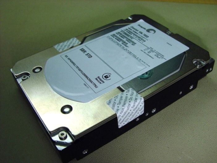
Security Level 2
Security Level 2 enhances the physical security mechanisms of a Security Level 1 cryptographic module by adding the require-
ment for tamper-evidence, which includes the use of tamper-evident coatings or seals on removable covers of the module. Tam-
per-evident coatings or seals are placed on a cryptographic module so that the coating or seal must be broken to attain physical
access to the critical security parameters (CSP) within the module. Tamper-evident seals (example shown in Figure 5, page 24) are
placed on covers to protect against unauthorized physical access. In addition Security Level 2 requires, at a minimum, role-based
authentication in which a cryptographic module authenticates the authorization of an operator to assume a specific role and per-
form a corresponding set of services.
Figure 5. Example of FIPS tamper evidence labels.
Note Image is for reference only, may not represent actual drive.
Seagate Enterprise Capacity 3.5 HDD v6 Serial ATA Product Manual, Rev. D 245.0 About self-encrypting drives Self-encrypting drives (SEDs) offer encryption and security services for the protection of stored data, commonly known as “protection of data at rest.” These drives are compliant with the Trusted Computing Group (TCG) Enterprise Storage Specifications as detailed in Section 2.13. The Trusted Computing Group (TCG) is an organization sponsored and operated by companies in the computer, storage and digital communications industry. Seagate’s SED models comply with the standards published by the TCG. To use the security features in the drive, the host must be capable of constructing and issuing the following two ATA commands: • Trusted Send • Trusted Receive These commands are used to convey the TCG protocol to and from the drive in their command payloads. 5.1 Data encryption Encrypting drives use one inline encryption engine for each port, employing AES-256 bit data encryption keys with AES-XTS mode to encrypt all data prior to being written on the media and to decrypt all data as it is read from the media. The encryption engines are always in operation and cannot be disabled. The 32-byte Data Encryption Key (DEK) is a random number which is generated by the drive, never leaves the drive, and is inaccessible to the host system. The DEK is itself encrypted when it is stored on the media and when it is in volatile temporary storage (DRAM) external to the encryption engine. A unique data encryption key is used for each of the drive's possible16 data bands (see Section 5.5). 5.2 Controlled access The drive has two security providers (SPs) called the "Admin SP" and the "Locking SP." These act as gatekeepers to the drive security services. Security-related commands will not be accepted unless they also supply the correct credentials to prove the requester is authorized to perform the command. 5.2.1 Admin SP The Admin SP allows the drive's owner to enable or disable firmware download operations (see Section 5.4). Access to the Admin SP is available using the SID (Secure ID) password or the MSID (Manufacturers Secure ID) password. 5.2.2 Locking SP The Locking SP controls read/write access to the media and the cryptographic erase feature. Access to the Locking SP is available using the BandMasterX or EraseMaster passwords. Since the drive owner can define up to 16 data bands on the drive, each data band has its own password called BandMasterX where X is the number of the data band (0 through 15). 5.2.3 Default password When the drive is shipped from the factory, all passwords are set to the value of MSID. This 32-byte random value can only be read by the host electronically over the interface. After receipt of the drive, it is the responsibility of the owner to use the default MSID password as the authority to change all other passwords to unique owner-specified values. Seagate Enterprise Capacity 3.5 HDD v6 Serial ATA Product Manual, Rev. D 25
5.3       Random number generator (RNG)
The drive has a 32-byte hardware RNG that it is uses to derive encryption keys or, if requested to do so, to provide random numbers
to the host for system use, including using these numbers as Authentication Keys (passwords) for the drive’s Admin and Locking SPs.

5.4       Drive locking
In addition to changing the passwords, as described in Section 5.2.3, the owner should also set the data access controls for the
individual bands.

The variable "LockOnReset" should be set to "PowerCycle" to ensure that the data bands will be locked if power is lost. In addition
"ReadLockEnabled" and "WriteLockEnabled" must be set to true in the locking table in order for the bands "LockOnReset" setting of
"PowerCycle" to actually lock access to the band when a "PowerCycle" event occurs. This scenario occurs if the drive is removed from
its cabinet. The drive will not honor any data read or write requests until the bands have been unlocked. This prevents the user data
from being accessed without the appropriate credentials when the drive has been removed from its cabinet and installed in another
system.

When the drive is shipped from the factory, the firmware download port is unlocked.

5.5       Data bands
When shipped from the factory, the drive is configured with a single data band called Band 0 (also known as the Global Data Band)
which comprises LBA 0 through LBA max. The host may allocate Band1 by specifying a start LBA and an LBA range. The real estate for
this band is taken from the Global Band. An additional 30 Data Bands may be defined in a similar way (Band2 through Band31) but
before these bands can be allocated LBA space, they must first be individually enabled using the EraseMaster password.

Data bands cannot overlap but they can be sequential with one band ending at LBA (x) and the next beginning at LBA (x+1).

Each data band has its own drive-generated encryption key and its own user-supplied password. The host may change the
Encryption Key (see Section 5.6) or the password when required. The bands should be aligned to 4K LBA boundaries.

5.6       Cryptographic erase
A significant feature of SEDs is the ability to perform a cryptographic erase. This involves the host telling the drive to change the data
encryption key for a particular band. Once changed, the data is no longer recoverable since it was written with one key and will be
read using a different key. Since the drive overwrites the old key with the new one, and keeps no history of key changes, the user
data can never be recovered. This is tantamount to an instantaneous data erase and is very useful if the drive is to be scrapped or
redispositioned.

5.7       Authenticated firmware download
In addition to providing a locking mechanism to prevent unwanted firmware download attempts, the drive also only accepts
download files which have been cryptographically signed by the appropriate Seagate Design Center.

Three conditions must be met before the drive will allow the download operation:
1.    The download must be an SED file. A standard (base) drive (non-SED) file will be rejected.
2.    The download file must be signed and authenticated.
3.    As with a non-SED drive, the download file must pass the acceptance criteria for the drive. For example it must be applicable to
      the correct drive model, and have compatible revision and customer status.

Seagate Enterprise Capacity 3.5 HDD v6 Serial ATA Product Manual, Rev. D                                                               26
You can also read