ProNest CNC - Field Service Bulletin 809560 Revision 3 September 2018 - Hypertherm
←
→
Page content transcription
If your browser does not render page correctly, please read the page content below
®
ProNest CNC

Field Service Bulletin

809560
Revision 3
September 2018
Hypertherm, Inc.                                                                                    Hypertherm Europe B.V.
Etna Road, P.O. Box 5010                                                                            Vaartveld 9, 4704 SE
Hanover, NH 03755 USA                                                                               Roosendaal, Nederland
603-643-3441 Tel (Main Office)                                                                      31 165 596907 Tel
603-643-5352 Fax (All Departments)                                                                  31 165 596901 Fax
info@hypertherm.com (Main Office Email)                                                             31 165 596908 Tel (Marketing)
800-643-9878 Tel (Technical Service)                                                                31 (0) 165 596900 Tel (Technical Service)
technical.service@hypertherm.com (Technical Service Email)                                          00 800 4973 7843 Tel (Technical Service)
800-737-2978 Tel (Customer Service)                                                                 technicalservice.emea@hypertherm.com
customer.service@hypertherm.com (Customer Service Email)                                            (Technical Service Email)
866-643-7711 Tel (Return Materials Authorization)
877-371-2876 Fax (Return Materials Authorization)                                                   Hypertherm (Shanghai) Trading Co., Ltd.
return.materials@hypertherm.com (RMA email)                                                         B301, 495 ShangZhong Road
                                                                                                    Shanghai, 200231
Hypertherm México, S.A. de C.V.                                                                     PR China
Avenida Toluca No. 444, Anexo 1,                                                                    86-21-80231122 Tel
Colonia Olivar de los Padres                                                                        86-21-80231120 Fax
Delegación Álvaro Obregón                                                                           86-21-80231128 Tel (Technical Service)
México, D.F. C.P. 01780                                                                             techsupport.china@hypertherm.com
52 55 5681 8109 Tel                                                                                 (Technical Service Email)
52 55 5683 2127 Fax
Soporte.Tecnico@hypertherm.com (Technical Service Email)                                            South America & Central America: Hypertherm Brasil Ltda.
                                                                                                    Rua Bras Cubas, 231 – Jardim Maia
Hypertherm Plasmatechnik GmbH                                                                       Guarulhos, SP – Brasil
Sophie-Scholl-Platz 5                                                                               CEP 07115-030
63452 Hanau                                                                                         55 11 2409 2636 Tel
Germany                                                                                             tecnico.sa@hypertherm.com (Technical Service Email)
00 800 33 24 97 37 Tel
00 800 49 73 73 29 Fax                                                                              Hypertherm Korea Branch
31 (0) 165 596900 Tel (Technical Service)                                                           #3904. APEC-ro 17. Heaundae-gu. Busan.
00 800 4973 7843 Tel (Technical Service)                                                            Korea 48060
technicalservice.emea@hypertherm.com (Technical Service Email)                                      82 (0)51 747 0358 Tel
                                                                                                    82 (0)51 701 0358 Fax
Hypertherm (Singapore) Pte Ltd.                                                                     Marketing.korea@hypertherm.com (Marketing Email)
82 Genting Lane                                                                                     TechSupportAPAC@hypertherm.com
Media Centre                                                                                        (Technical Service Email)
Annexe Block #A01-01
Singapore 349567, Republic of Singapore                                                             Hypertherm Pty Limited
65 6841 2489 Tel                                                                                    GPO Box 4836
65 6841 2490 Fax                                                                                    Sydney NSW 2001, Australia
Marketing.asia@hypertherm.com (Marketing Email)                                                     61 (0) 437 606 995 Tel
TechSupportAPAC@hypertherm.com (Technical Service Email)                                            61 7 3219 9010 Fax
                                                                                                    au.sales@Hypertherm.com (Main Office Email)
Hypertherm Japan Ltd.                                                                               TechSupportAPAC@hypertherm.com
Level 9, Edobori Center Building                                                                    (Technical Service Email)
2-1-1 Edobori, Nishi-ku
Osaka 550-0002 Japan                                                                                Hypertherm (India) Thermal Cutting Pvt. Ltd
81 6 6225 1183 Tel                                                                                  A-18 / B-1 Extension,
81 6 6225 1184 Fax                                                                                  Mohan Co-Operative Industrial Estate,
HTJapan.info@hypertherm.com (Main Office Email)                                                     Mathura Road, New Delhi 110044, India
TechSupportAPAC@hypertherm.com (Technical Service Email)                                            91-11-40521201/ 2/ 3 Tel
                                                                                                    91-11 40521204 Fax
                                                                                                    HTIndia.info@hypertherm.com (Main Office Email)
                                                                                                    TechSupportAPAC@hypertherm.com
                                                                                                    (Technical Service Email)

© 2018 Hypertherm, Inc. All rights reserved.
XPR, EDGE, HPRXD, Phoenix, Powermax, PowerPierce, ProNest, SureCut, True Hole, and Hypertherm are trademarks of Hypertherm, Inc. and may be registered in the
United States and/or other countries. All other trademarks are the property of their respective holders.
Environmental stewardship is one of Hypertherm’s core values, and it is critical to our success and our customers’ success. We are striving to reduce the environmental
impact of everything we do. For more information: www.hypertherm.com/environment.

1/28/16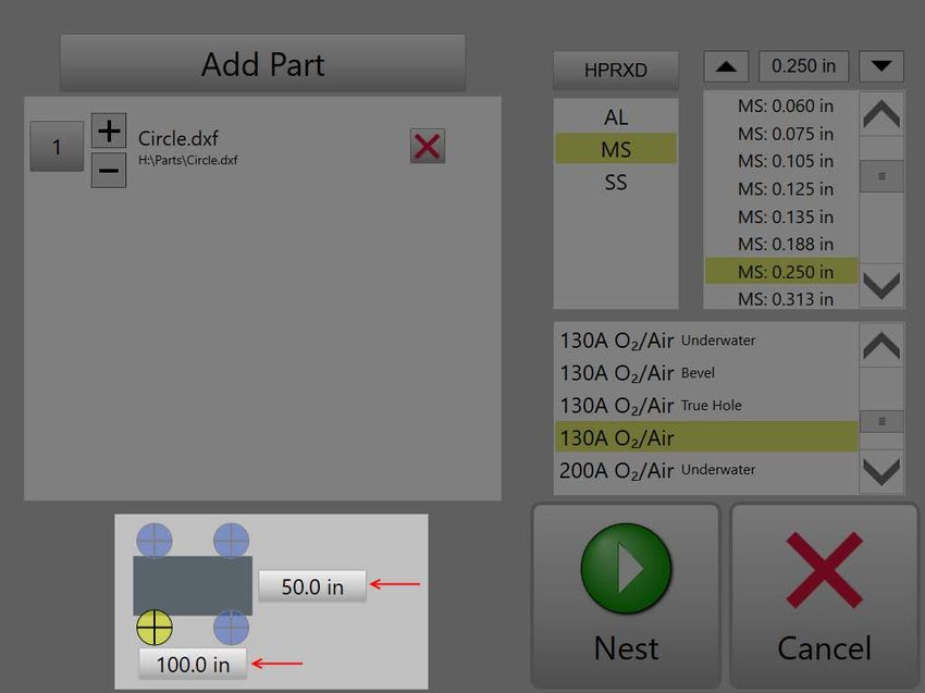
Contents
Overview ....................................................................................................................................... 4
Basic workflow .............................................................................................................................. 4
Base features and optional modules ............................................................................................. 4
  Base module: ProNest CNC ...................................................................................................... 4
  Optional module: True Shape Nesting ...................................................................................... 4
Open ProNest CNC ...................................................................................................................... 4
Adding parts .................................................................................................................................. 5
  CAD files ................................................................................................................................... 5
    Supported CAD file formats ................................................................................................... 5
    Rules for CAD files ................................................................................................................ 5
    Adding CAD files to the part list ............................................................................................. 6
  Adding Shape Library parts ....................................................................................................... 7
Changing the machine .................................................................................................................. 7
Selecting a material type and thickness ........................................................................................ 9
Selecting a class ......................................................................................................................... 10
    True Hole® ........................................................................................................................... 11
    Fine Feature ........................................................................................................................ 11
    HDi ....................................................................................................................................... 11
    Bevel and True Bevel .......................................................................................................... 12
    Moving Pierce ...................................................................................................................... 12
    Thick Pierce ......................................................................................................................... 12
    Underwater .......................................................................................................................... 13
    Edge Pierce Only ................................................................................................................. 13
    Shielded / Unshielded .......................................................................................................... 13
Set plate size and home position ................................................................................................ 14
  Plate dimensions ..................................................................................................................... 14
  Home position ......................................................................................................................... 15
Nesting ........................................................................................................................................ 15
  Creating a nest ........................................................................................................................ 15
  Saving nests for future use ...................................................................................................... 16
  Creating multiple nests ............................................................................................................ 16
Errors and troubleshooting .......................................................................................................... 17
    Not all parts are nested........................................................................................................ 17
    Part is Larger than the Plate ................................................................................................ 17
    Empty Drawing File!............................................................................................................. 17
    No parts nested – please check your part ........................................................................... 17
    Parts on the nest are severely over or undersized .............................................................. 17
Frequently asked questions ........................................................................................................ 17

                                                                                                                                                 3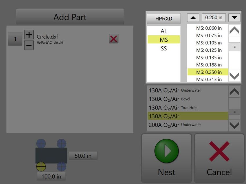
Overview
ProNest CNC is a simple but powerful software program designed to enable optimal cut quality
and material utilization for part programs created on the EDGE Connect CNC (computer
numeric control).
With ProNest CNC, you can build a part list and then use ProNest CNC’s powerful nesting
algorithms to nest those parts to maximize plate usage. Built-in process expertise ensures that
you will get optimal cut quality when cutting the CNC program for the nest.

Basic workflow
ProNest CNC is designed to create a single nest at a time. This means that you can add
enough parts to fit on a sheet, nest the parts, create a program for that nest and then cut it.

Base features and optional modules
Base module: ProNest CNC
The base module of ProNest CNC comes pre-installed on every Hypertherm EDGE Connect
CNC. The base module allows you to add a single CAD or Shape Manager part to the part list
and then create a nest containing one or more copies of that part.

Optional module: True Shape Nesting
The True Shape Nesting module enables you to build a part list containing multiple CAD files.
Add as many different CAD files as you want and ProNest CNC will nest the parts together on
the sheet.
Note: To learn more about the True Shape Nesting module, please contact your table
manufacturer for a free 30 day trial.

Open ProNest CNC
In Phoenix, ProNest CNC can be opened in one of two ways:
   1. In the Main screen, choose the Shape Manager button.

   2. Choose the ProNest CNC button.
   -or-
   1. In the Main screen, choose the Shape Manager button.
   2. Choose a library shape.
   3. Enter properties for the shape, as needed.

   4. Choose OK.
You will be taken to ProNest CNC, with that library shape already in the part list.

                                                                                                  4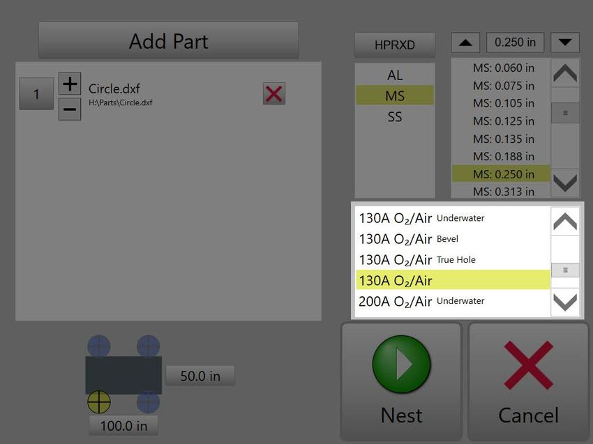
Adding parts
ProNest CNC supports two sources for bringing in parts: external CAD files or Shape Library
parts.

CAD files
CAD files are typically loaded onto a USB stick / thumb drive, which is then plugged in to the
CNC and added in Phoenix. If your CNC is connected via Ethernet or Wi-Fi, you can also add
source CAD files from a network folder.

Supported CAD file formats
The following CAD file formats are allowed to be nested with ProNest CNC.

   •   .dxf
   •   .dwg
   •   .dgn
   •   .cam

Rules for CAD files
  1. Only include cut geometry.
   When a CAD file is added in ProNest CNC, all geometry found in the file is cut. Even if there
   is a designated layer for marking, the geometry on that layer will still be cut. For this reason,
   make sure that your drawing has been cleaned and only cut geometry is included in the
   CAD file.

  2. Multi-part CAD files are not supported.
  If a CAD file contains multiple separate parts, that file can’t be imported into ProNest CNC.
  Only single-part CAD files are supported. Note that CAD files that contain entire nests of
  parts can’t be added in ProNest CNC.

  3. Be sure file units of the CAD file match the units used in Phoenix.
  ProNest CNC assumes that your CAD files are drawn with the same units as the CNC.
  Phoenix can be set to English or Metric Units. When in English Units, CAD files should be
  drawn in inches. When in Metric Units, CAD files should be drawn in millimeters.
  If units are different, your parts will be too big or too small. For instance, if ProNest CNC is
  set to use English Units and you import a part that was drawn in millimeters, the part will be
  severely oversized.
  If you have CAD files with incorrect units, please correct the problem in CAD instead of
  adjusting the CNC’s units.
  To view the units used by Phoenix:

       •   On the Main screen, choose Setups.

                                                                                                     5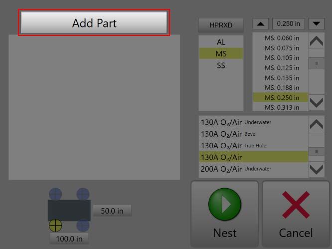
Adding CAD files to the part list
   1. Open ProNest CNC.
   2. Choose the Add Part button.

   3. Browse to the folder location containing your CAD files. This might be a USB memory
      stick or network folder.
   4. Select a CAD file, then choose Open.
      The CAD file will be added to the part list.
   5. Use the +/- buttons to adjust the quantity of the part. You can also choose the number to
      the left of the part and type in a quantity.

   6. If you have the True Shape Nesting module, you can repeat steps 2-5 to add
      subsequent CAD files.

                                                                                              6
Adding Shape Library parts
Note: You can only add a single Shape Library part to the part list at a time, even if you have the
True Shape Nesting module.
1. In the Main screen, choose the Shape Manager button.
2. Choose a library shape.
3. Enter properties for the shape, as needed.
4. Choose OK.
You will be taken to ProNest CNC, with that shape already in the part list.
5. Use the +/- buttons to adjust the quantity of the library part. You can also choose the
number to the left of the part and type in a quantity.
At this point, you can add additional CAD files to the part list (as described above), if
needed.
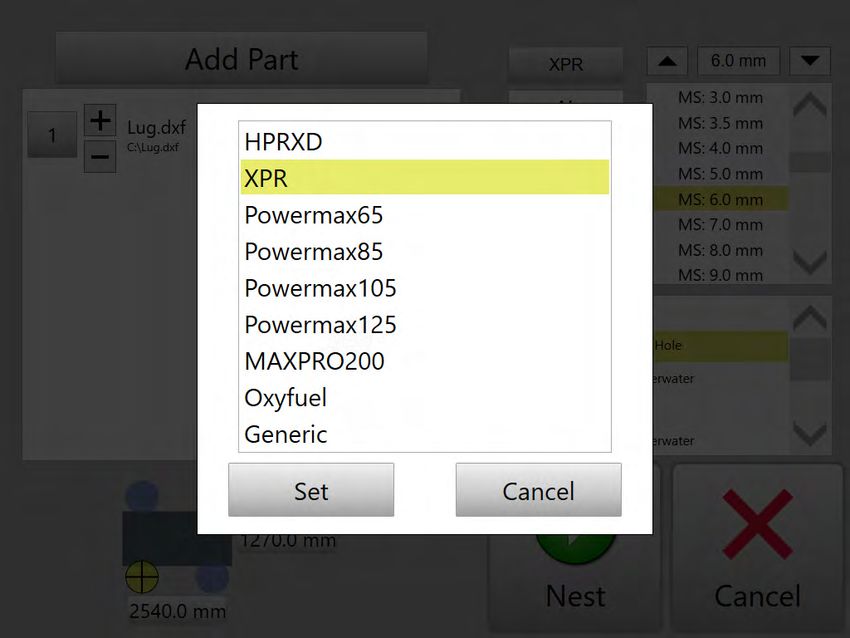
Changing the machine
ProNest CNC always has a current machine which controls the materials and performance
applications that are available. This machine should correspond to the cutting system that will
be used to cut the nest.
Note: In most cases, ProNest CNC’s current machine will match your cutting machine hardware
and you will not need to make any changes. ProNest CNC only supports Station 1.
To change the current machine:
1. In ProNest CNC, choose the machine button.
2. Choose a machine from the list, then choose Set.
7Changing a machine may be used for applications where there are multiple cut tools (for
instance, plasma and oxyfuel) and you want to create a nest for a specific machine process.
8Selecting a material type and thickness
ProNest CNC assigns different SureCut™ parameters such as feedrate, kerf, leads, and
separation distances on the nest based on material. It is important to select the correct material
type and thickness for the nest.
• In the upper-right of the screen, choose the required material type.
Choices include:
MS = Mild steel
SS = Stainless steel
AL = Aluminum
Once a type has been selected, choose the thickness that matches your plate.
• Use the arrows or scroll bar to page through the list in the upper right.
-or-
• Choose the thickness box at the top of the pane and type in a thickness.
Note: If you are cutting with an oxyfuel tool or generic plasma, neither material type nor class
are available. Only thickness needs to be chosen.
9Selecting a class
In ProNest CNC, class is used for plasma applications to apply specific cutting parameters
based on the consumables that will be used to cut a nest. It is also used to apply performance
applications such as True Hole® and other technologies to parts on the nest.
The list of available classes is based on the machine (HPR, XPR, etc.), material type and
thickness that is selected.
For plasma systems, the amperage and cutting gas/shield gas can be selected in ProNest CNC
using class. In selecting an amperage and gas, you are specifying which consumables
(electrode, nozzle, etc.) should be used for the parts on the nest. When selecting a class, keep
in mind:
• Cutting at a higher amperage is generally faster than cutting at a lower amperage.
• Selecting a lower amperage with a slower cut speed will typically result in a better
quality cut than cutting at a higher amperage.
You can also use class to apply performance applications and other technologies to parts in
ProNest CNC:
10True Hole®
Produces bolt hole quality with virtually no hole taper and minimal ding on mild steel. When True
Hole is selected, it is applied to a part's holes automatically based on the ratio of material
thickness to hole diameter. So in a given part, with the True Hole class selected, some holes
may get True Hole while other holes do not.
Pros
• Automatically delivers "bolt-hole" quality
• Virtual elimination of hole taper
• Ding is reduced and biased to the outside of the hole
Cons
• Slower than a standard cut
• Slightly longer cut length (due to adjusted leads)
Nest programs that do contain True Hole have a “with True Hole technology” indicator on the
Main screen in Phoenix.
Fine Feature
Fine Feature is a technology that is designed for jobs in which the greatest importance is placed
on achieving the best possible finish on the cut surface, a sharp top edge, and tight control over
angle deviation.
Pros
• Best finish on the cut surface
• Sharp top edge quality
• Tight control over angle deviation
Cons
• Slower than a standard cut
Note: XPR does not have a Fine Feature class. XPR cut charts are already optimized to provide
superior cutting on mild steel, stainless steel, and aluminum throughout all thin and thick
processes.
HDi
HyDefinition inox (HDi) 60 A cutting process for thin stainless steel that produces high quality
cuts with minimal dross.
Pros
• Sharp top edge quality
• Shiny surface finish
• Superior angularity with reduced angle variation
• Less dross
11Cons
• Only for thin material
• Only available at 60 A
• Requires F5/N2 gas
Note: XPR does not have a HDi class. XPR cut charts are already optimized to provide superior
cutting on mild steel, stainless steel, and aluminum throughout all thin and thick processes.
Bevel and True Bevel
Indicates to ProNest CNC that Hypertherm bevel consumables (shield, nozzle, electrode, and
so on) are in use.
Pros
• Better consumable life when cutting non-bevel (perpendicular)
Cons
• Only available at certain amperages
• Requires separate consumable set
Note: Bevel cuts (angled non-perpendicular edges on parts) are not possible with ProNest CNC
parts. Selecting a class with Bevel or True Bevel only indicates that Hypertherm bevel
consumables will be used to cut the nest. For XPR users, True Bevel is visible but not
supported with ProNest CNC. This is because all XPR consumables are bevel consumables.
Moving Pierce
A pierce technique that is combined with PowerPierce® technology to extend stainless steel
pierce capability for the HPR800XD to 4 inches (100 mm) and for the HPR400XD to 3 inches
(75 mm).
Pros
• Eliminates need for pre-piercing
• Ability to pierce thick stainless without an edge pierce
• Piercing interior profiles with plasma is possible (as long as the hole is large
enough and has a linear lead-in)
• Keeps torch away from molten material
Cons
• Can only be applied to Linear style lead-ins
• Leaves molten slag ("rooster tail") that can spatter onto adjacent parts
• Requires high amperage
Note: XPR does not have a Moving Pierce class. XPR cut charts are already optimized to
provide superior cutting on mild steel, stainless steel, and aluminum throughout all thin and thick
processes.
12Thick Pierce
Uses special piercing commands in EDGE Connect for the HPRXD Thick Pierce.
Pros
• Ability to pierce thick material without an edge pierce
Cons
• Not available for Stainless Steel or Aluminum
Note: XPR does not have a Thick Pierce class. XPR cut charts are already optimized to provide
superior cutting on mild steel, stainless steel, and aluminum throughout all thin and thick
processes.
Underwater
Underwater cutting can significantly reduce the level of noise and smoke generated by normal
plasma cutting, as well as the glare of the plasma arc. Hypertherm has developed underwater
cut charts for mild steel at 80 A, 130 A, 200 A, 260 A, and 400 A. Select this class if the nest will
be cut with underwater plasma.
Pros
• Reduced noise, smoke and glare compared to normal plasma cutting
• Reduced heat distortion and warping
• Parts can be handled immediately after they are cut
• Available at many different amperages
Cons
• Slower than a standard cut
• Cut charts do not support Stainless Steel or Aluminum
• Not compatible with True Hole
• Some dross may develop at the bottom of the piece as the molten metal cools
down faster and remains attached to the part.
Edge Pierce Only
For thicker materials, edge pierces may be required when cutting at specific amperages and
with certain gases. This is because a traditional pierce wouldn't physically cut through the plate.
An "Edge Pierce Only" class indicates that when cutting that thickness with the specified
amperage and assist gas, you must use edge piercing for parts. Typically, this choice isn’t used
with ProNest CNC.
Shielded / Unshielded
For Powermax cutting systems, this indicates to ProNest CNC whether the consumable set in
use is shielded (with a shield) or unshielded (with a deflector).
Because kerf compensation and other cutting parameters may vary based on the consumables
in use, it is important to select a class that matches the consumables in use on your Powermax
system. This will ensure the ProNest CNC includes the correct parameters in the program for
each nest.
13Please consult the Powermax Operator Manual for more information.
Set plate size and home position
Plate dimensions
In Phoenix, there is always a default plate/sheet size. This is set on the Setups > Cutting page
using the Plate Size setting.
In ProNest CNC, you can enter a cutting area that is different from the default Plate Size. This
may be useful if you need to limit cutting to an area that is smaller than the default plate size,
such as with a remnant plate.
To set the cutting area for a plate in ProNest CNC:
1. Choose either dimension box in the lower-left of the screen.
2. Enter a new value.
14Home position
To change the home position that is used for a nest in ProNest CNC:
• Choose one of the four home position indicators on the plate image.
When you change the home position for a given nest:
• This corner you choose will become the point of origin for automatic nesting. Nesting will
begin from this point.
Nesting
Creating a nest
After the parts have been added to the part list and the material and class are set, you will be
ready to nest the parts and create a program for the nest.
• Choose the Nest button.
After choosing Nest, ProNest CNC will complete the following operations:
• Parts in the part list are processed, which includes adding lead-ins/lead-outs.
• Parts are automatically nested on the sheet
• SureCut™ technology is applied, ensuring optimal cut quality
• NC program for the nest is created
Once ProNest CNC is finished nesting, the nest that is created will become the current “part” in
Phoenix, ready for cutting. You can interact with this nest just as you would any other part in
Phoenix.
Notes:
• The orientation of a simple shape might not match the preview. ProNest CNC will
determine the best orientation based on the home location you selected and the
geometry of the part.
• If you choose the Cancel button prior to nesting, you can still view and cut the
part that is selected. However, the part will not be processed through ProNest CNC.
15Note: After nesting, if you’ve selected a cut area that is larger than the plate size in Phoenix, this
will be indicated by a “Part is Larger than the Plate” warning message.
Saving nests for future use
You can save any nest created in ProNest CNC by simply choosing Files > Save to Disk from
the Main screen. Choose the Help soft key on the Save to Disk screen for more information.
Creating multiple nests
Nests in ProNest CNC are created one at a time. If you require a list of parts that takes up more
than one sheet, you will need to create the nests one at a time.
Tip: If you have to cut multiple copies of a nest, you can do so by simply re-running the same
nest program on the CNC.
16Errors and troubleshooting
Not all parts are nested
After choosing Nest, a message indicates that not all parts in the part list were nested (for
example, “2 of 3 parts nested”). Possible reasons:
• Not all parts in the part list will fit on the sheet.
• Single part is too big to fit on the sheet.
• Some parts in the part list are invalid, empty, or contain multiple exteriors (see below).
Part is Larger than the Plate
This error/warning may appear after choosing Nest. Possible reason:
• Cut area selected in ProNest CNC is larger than the plate size in Phoenix.
Empty Drawing File!
This error may appear after choosing Nest. Possible reason:
• Invalid or empty CAD files were added to the part list.
No parts nested – please check your part
This error may appear after choosing Nest. It indicates that none of the parts in the part list are
suitable for nesting, therefore no nest was created. Possible reasons:
• Invalid or empty CAD files were added to the part list.
• A single part is too big to fit on the sheet.
• A CAD file containing multiple parts was added.
Parts on the nest are severely over or undersized
Check the units used in the CAD file. See “Rules for CAD files” for more information.
Frequently asked questions
How do I view the NC code of a part/nest created with ProNest CNC?
The Phoenix Shape Wizard or a text editor can be used to review the program for a nest
created by ProNest CNC.
I have nests I created in the full desktop version of ProNest, how do I load them on my CNC?
You can still load the nest programs on the CNC. However, nest programs cannot be
added to the ProNest CNC Part List nor can they be nested.
Can I bring in a 3D part file (such as SOLIDWORKS or Inventor parts) and nest that using
ProNest CNC?
No. Only DXF, DWG, DGN, or CAM formats are accepted. You would need to convert
that part to an acceptable format before importing it in ProNest CNC.
Is True Hole supported? How can I tell if a hole has True Hole once parts have been nested?
Yes. True Hole is applied to qualifying holes, as long as a material class with “True Hole”
is selected prior to choosing Nest.
17If True Hole exists on the current part/nest in Phoenix, a “True Hole technology in use”
message will appear on the Main screen.
Can nests be saved for later use?
Once a nest is created using ProNest CNC, it becomes the “current part” in Phoenix. It
can be saved just as you would any other part in Phoenix
Can I bevel parts with ProNest CNC?
Beveling - applying non-perpendicular cut angles to part edges – is not supported with
ProNest CNC. The term “Bevel” in the ProNest CNC material / class selection panes
refers to Hypertherm Bevel consumables. For XPR systems, standard consumables
(which are all bevel-capable) are used for all classes, including True Bevel.
Can I add multiple Shape Library parts to the part list and nest them together?
Only one Shape Library part can be added to the part list at a time.
Does ProNest CNC support marking?
No. All geometry found in CAD files is cut. Even if there is a designated layer for
marking, the geometry on that layer will still be cut.
Is Collision Avoidance available with ProNest CNC?
At this time, ProNest’s Collision Avoidance feature is not applied to any nests created
with ProNest CNC. There are other aspects of Rapid Part technology, however, that may
be applied when using an EDGE Connect with a Sensor THC, including:
• Automatic crossover height calibration
• Preflow during initial height sense (IHS)
• Skip IHS
Can I use a setup (.PN or .PNCA) from the full desktop version of ProNest on ProNest CNC?
No. ProNest CNC requires its own unique configuration archives.
Is waterjet or laser supported on ProNest CNC?
No. Currently only plasma and oxyfuel cutting is supported.
18You can also read