PTP 820E System Release 10.9 - Quick Installation Instructions - Cambium Networks
←
→
Page content transcription
If your browser does not render page correctly, please read the page content below
Quick Installation Instructions

PTP 820E
System Release 10.9
Accuracy
While reasonable efforts have been made to assure the accuracy of this document, Cambium Networks assumes no
liability resulting from any inaccuracies or omissions in this document, or from use of the information obtained herein.
Cambium reserves the right to make changes to any products described herein to improve reliability, function, or design,
and reserves the right to revise this document and to make changes from time to time in content hereof with no
obligation to notify any person of revisions or changes. Cambium does not assume any liability arising out of the
application or use of any product, software, or circuit described herein; neither does it convey license under its patent
rights or the rights of others. It is possible that this publication may contain references to, or information about Cambium
products (machines and programs), programming, or services that are not announced in your country. Such references
or information must not be construed to mean that Cambium intends to announce such Cambium products,
programming, or services in your country.
Copyrights
This document, Cambium products, and 3rd Party software products described in this document may include or describe
copyrighted Cambium and other 3rd Party supplied computer programs stored in semiconductor memories or other
media. Laws in the United States and other countries preserve for Cambium, its licensors, and other 3rd Party supplied
software certain exclusive rights for copyrighted material, including the exclusive right to copy, reproduce in any form,
distribute and make derivative works of the copyrighted material. Accordingly, any copyrighted material of Cambium,
its licensors, or the 3rd Party software supplied material contained in the Cambium products described in this document
may not be copied, reproduced, reverse engineered, distributed, merged or modified in any manner without the express
written permission of Cambium. Furthermore, the purchase of Cambium products shall not be deemed to grant either
directly or by implication, estoppel, or otherwise, any license under the copyrights, patents or patent applications of
Cambium or other 3rd Party supplied software, except for the normal non-exclusive, royalty free license to use that
arises by operation of law in the sale of a product.
Restrictions
Software and documentation are copyrighted materials. Making unauthorized copies is prohibited by law. No part of
the software or documentation may be reproduced, transmitted, transcribed, stored in a retrieval system, or translated
into any language or computer language, in any form or by any means, without prior written permission of Cambium.
License Agreements
The software described in this document is the property of Cambium and its licensors. It is furnished by express license
agreement only and may be used only in accordance with the terms of such an agreement.
High Risk Materials
Cambium and its supplier(s) specifically disclaim any express or implied warranty of fitness for any high risk activities
or uses of its products including, but not limited to, the operation of nuclear facilities, aircraft navigation or aircraft
communication systems, air traffic control, life support, or weapons systems (“High Risk Use”). Any High Risk is
unauthorized, is made at your own risk and you shall be responsible for any and all losses, damage or claims arising out
of any High Risk Use.

                             © 2019 Cambium Networks Limited. All Rights Reserved.

                                                      Page 2 of 16
Introduction
This guide provides basic instructions for setting up and configuring a PTP 820E 1+0 link. For more detailed instructions:

    •   Installation Guide for PTP 820E – Detailed instructions for hardware assembly of all supported PTP 820E link
        types.

    •   User Guide for PTP 820C, PTP 820S, and PTP 820E – Detailed instructions for software configuration.

                                    PTP 820E Rear View (Left) and Front View (Right)

                        PTP 820E Interfaces                                     Cable Gland Construction

                                                       Page 3 of 16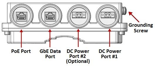
PoE Injector                  PoE Injector Interfaces

               Page 4 of 16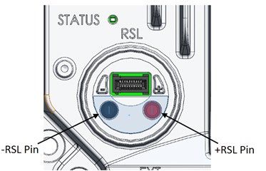
Pole Mount Assembly and Installation

     Note

     Do not remove the transparent pressure window located on the
     antenna interface.

                                                                    For vertical
                             For horizontal                         polarization, locate
                             polarization, locate                   the twist with the
                             the twist with the                     letter “V” at 3
                             letter “H” at 3                        o’clock and fasten
                             o’clock and fasten                     the two screws.
                             the two screws.

                                               Page 5 of 16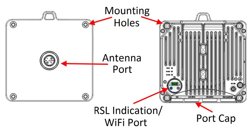
Mount the PTP 820E on the antenna using the four
               M8 captive screws and washers that are supplied,
               assembled, in the PTP 820E, and tighten the screws.
               When tightening the captive screws, use 20 Nm
               torque. In order to avoid misalignment, screws should
               be tightened progressively.

Page 6 of 16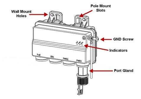
Cabling
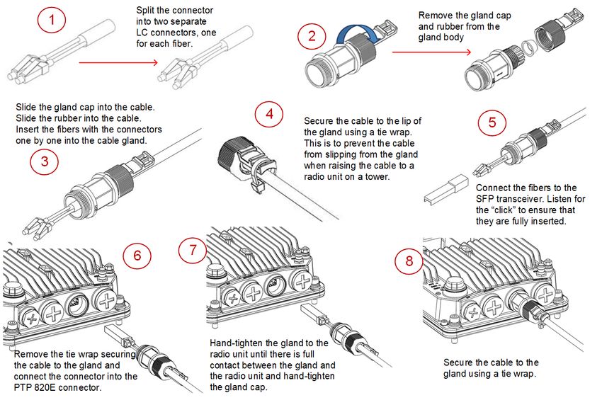
To connect an optical Ethernet cable and SFP:
Page 7 of 16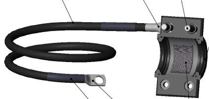
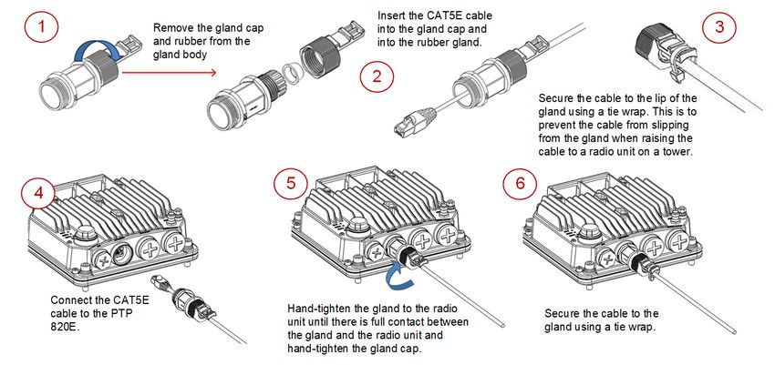
To connect an electrical Ethernet cable:

To connect a DC power cable:

                                           Page 8 of 16
Cable Grounding
• No grounding is required for optical (SFP) cables.
• External shielded CAT5E cable should be grounded to the antenna tower at the top (next to the PTP 820 unit)
and the bottom of the external run and every 50m using the kit CAT5E_gnd_kit.
Page 9 of 16Installing and Connecting a PoE Injector
To mount a PoE Injector on the wall:
Mount and tighten the PoE Injector to a
1 wall using two M6 bolts and anchors. 2
Drill two 6mm diameter
holes with 100mm
Use Anchor Stainless Steel with
between the center of the
flanged Hexagonal nut M6X70.
holes.
Insert the anchors with the bolts, place
3 the washers on the bolts, and tighten the
nuts.
Page 10 of 16To mount a PoE Injector on a pole: To mount a PoE Injector on a 19” rack:
Mount the Injector to a 19"
1 rack using a 19" rack adaptor.
Mount the Injector on
the adaptor through
2 the wall mounting
holes, using M6
Mount and tighten the screws and washers.
1 Injector to a 114mm
pole using a stainless
steel hose clamp.
Pass the hose Mount the adaptor
2 clamp through the 3 to the rack using
four M6 screws
pole mount slots. and cage nuts.
Attach the Injector
3 to the pole.
Connect the ends of the
4 hose clamp and tighten
using the captive screw.
To mount a PoE Injector on an ETSI rack: To ground a PoE Injector:
1. On the right side of the PoE Injector, loosen the screw,
1 Mount the PoE Injector to an ETSI plain washer, and serrated washer.
rack using a 19" rack adaptor and
2. Place the cable lug supplied with the PoE Injector kit
ETSI adapting ears.
between the plain and serrated washer.
3. Tighten the screw.
Connect ETSI adapting
2 ears to a 19" rack adaptor To connect the PoE Injector cables:
using four M6 screws.
• The total length of the cable between the PTP 820E
Mount the PoE Injector port and the Switch/Router the device is connected to
on the adaptor through should not exceed 100m/328ft. This length includes the
3 the wall mounting holes, connection between the PTP 820E and the PoE Injector
using M6 screws and (X1 + X2 ≤ 100m/328ft in the figure to the right).
washers.
• The length of the cable connecting the customer
equipment to the PoE injector should not be longer
than 10m (according to ANSI/TIA-568 standard).
Mount the 19" rack
adaptor with the ETSI
4 ears on the ETSI rack
using four M6 screws
and cage nuts.
Page 11 of 16Grounding the PTP 820E
1 Loosen the nut, plain washer, and serrated
washer from the GND stud, using the metric
offset hexagon key and the wrench.
2 Place the cable lug supplied with the grounding kit
in place on the screw and secure the cable lug.
3 Connect the second side of the GND cable to
the main or terminal ground bar of the site.
4 Perform a resistance test between the 2 lugs of the
GND cable and verify that the result is 0-2 ohms.
Notes:
The unit’s earthing screw terminal shall be permanently
connected to protective earth in a building installation in
accordance with applicable national code and regulations
by a service person.
A 2-pole circuit breaker, a branch circuit protector, suitably certified in accordance with applicable national code and
regulations, rated maximum 20A, shall be installed for full power disconnection in a building installation.
Any outdoor antenna cable shield shall be permanently connected to protective earth in a building installation.
Connecting to the Unit:
1. Connect your laptops LAN port to the MGT port on the PTP 820E.
2. Configure an IP address on the laptop within the same subnet as
the PTP 820E unit. The default PTP 820 IP address is 192.168.1.1. Set
the PC address to e.g. 192.168.1.10 and subnet mask to
255.255.255.0. Record the initial settings before changing.
3. On the laptop, open the Internal Protocol (TCP/IP) Properties page
and set the parameters shown in the figure on the right.
4. Open a web browser (Internet Explorer or Mozilla Firefox), enter
the default IP address “192.168.1.1” in the Address Bar. Once the
Login page opens, enter “admin” in both the User Name and
Password fields, and click Apply.
Page 12 of 16Changing the Default IP Address
Select Platform > Management > Networking > Local. The Local Networking Configuration page opens.
Select IPv4 or IPv6. The unit will
use the selected protocol when
initiating communications.
Description of
unit (optional)
You can enter an IP address
in IPv4 format (use the IP
address field) or IPv6 format
(use the IPv6 Address field).
Before configuring the radio link, ensure that
both ends of the link have unique IP addresses.
Page 13 of 16Installing the Activation Key
New PTP 820E units are delivered with a default activation key that enables you to manage and configure the unit.
Additional feature and capacity support requires you to enter an activation key cipher in the Activation Key Configuration
page. Contact your vendor to obtain your activation key cipher.
Enter the activation
key cipher here
and click Apply.
To activate Demo mode,
select Enable here and
click Apply.
Displays the number of
hours that remain before
demo mode expires.
If the activation-key-enabled capacity and feature set is exceeded, an Activation Key Violation alarm occurs and the Web
EMS displays a yellow background and an activation key violation warning. After a 48-hour grace period, all other alarms
are hidden until the capacity and features in use are brought within the activation key’s capacity and feature set.
Demo mode is available, which enables all features for 60 days. When demo mode expires, the most recent valid activation
key goes into effect.
To enter a new activation key, select Platform > Activation Key > Activation Key Configuration. The Activation Key
Configuration page opens.
Page 14 of 16Configuring the Link
The Web EMS provides wizards to configure radio links. The wizards guide you through configuration of the basic radio
parameters and services necessary to establish a working pipe link.
To configure a 1+0 link using the Quick Configuration wizard, select Quick Configuration > PIPE > Single Carrier > 1+0.
Page 1 of the 1+0 Quick Configuration wizard opens.
1 2
Select an Ethernet interface or LAG for the link. Set the transmission and
Click Create LAG to open a wizard that guides received radio frequency in MHz.
you through the steps to create a LAG.
Select a radio
interface for the link. Enter the desired TX signal level
Select the Attached Interface type for (TSL). The range of values depends
the service that will connect the radio on the frequency and RFU type.
and Ethernet interfaces: Select On or Off to mute or
• s-tag – All S-VLANs and untagged unmute the TX output of the RFU.
frames are classified into the service.
• dot1q – All C-VLANs and untagged
3 frames are classified into the service.
4
Select the MRMC script you want
to assign to the radio.
Select Yes to configure in-band
management or No if you do not
need in-band management.
Select the ACM mode: Fixed or Adaptive. If you selected Yes above, select
• Fixed ACM mode applies constant TX and the management VLAN.
RX rates. Select this box if you want to use the
• In Adaptive ACM mode, TX and RX rates are Ethernet interface as well as the radio
dynamic. An ACM-enabled radio system interface for in-band management.
automatically chooses which profile to use
according to channel fading conditions.
If you selected Fixed in the Operational Mode field, the Profile field
appears instead of these fields. Select the ACM profile for the radio in
the Profile field.
If you selected Adaptive in the Operational Mode field, enter the
maximum and minimum profiles for the script in these fields.
5
Review the parameters and click Submit to
complete configuration of the link. After you
click Submit, the unit is reset.
Page 15 of 16Link Verification
Verify that the Received Signal Level (RSL) is up to +/- 4 dB from
the expected (calculated) level at both ends of the link.
You can measure the RSL at the BNC port indicated in the figure
to the left. The voltage at the BNC port is 1.XX where XX is the
RSL level. For example: 1.59V means an RSL of -59 dBm. Note
that the voltage measured at the BNC port is not accurate and
should be used only as an aid).
Verify that the Radio Bit Error Rate (BER) is 10E-11 or higher.
If working with ATPC, verify that ATPC is operating as expected
(RSL = reference level).
To display the current RSL (RX)
To display the BER using the Web EMS, To display the RSL PMs using the Web using the Web EMS, go to the
go to the Aggregate PM report (Radio > EMS, go to the Radio Parameters page Radio Parameters page (Radio >
PM & Statistics > Aggregate). (Radio > PM & Statistics > Signal Level). Radio Parameters).
Page 16 of 16You can also read