Putting the Fish in the Fish Tank: Immersive VR for Animal Behavior Experiments
←
→
Page content transcription
If your browser does not render page correctly, please read the page content below
To appear in Proc. 2012 ICRA

                            Putting the Fish in the Fish Tank:
                      Immersive VR for Animal Behavior Experiments
                                       Sachit Butail, Amanda Chicoli and Derek A. Paley

   Abstract— We describe a virtual-reality framework for inves-          environment in response to the animal’s position, orientation
tigating startle-response behavior in fish. Using real-time three-       and velocity. The attractiveness of this automation is that
dimensional tracking, we generate looming stimuli at a specific          it enables realistic behavioral experiments while allowing
location on a computer screen, such that the shape and size of
the looming stimuli change according to the fish’s perspective           control over the animal’s perceived environment. For ex-
and location in the tank. We demonstrate the effectiveness of            ample, by way of controlling where, how, and when to
the setup through experiments on Giant danio and compute                 present a stimulus, this technique promises to investigate
the success rate in eliciting a response. We also estimate visual        aspects of animal behavior such as visual perceptual volume,
startle sensitivity by presenting the stimulus from different            what qualifies as threat, and quorum sensing [12]. The basic
directions around the fish head. The aim of this work is to
provide the basis for quantifying escape behavior in fish schools.       framework is a visual feedback loop that automates the
                                                                         process of presenting the stimulus via a computer screen
                                                                         based on criteria on the animal’s pose.
                     I. INTRODUCTION                                        Fish-tank virtual-reality (VR) uses the viewer’s head pose
   The collective response of a fish school to a predator                to dynamically update the display on a screen [13]. This
is a rapidly propagating wave of visual and hydro-acoustic               concept is used in augmented reality systems with head-
information transmitted via local interactions that can travel           mounted gear or visual tracking [13], [14]. A virtual-reality
faster than the speed of an approaching predator [1]. Escape             system changes the image on the screen based on the
behaviors such as these are part of group communication                  viewer’s perspective. The importance of VR is unknown for
strategies that inspire the design of reactive multi-agent               animal behavior experiments. Preliminary results show an
robotic systems [2], control algorithms [3], [4], and the                increased probability of response with virtual-reality stimuli
design of autonomous systems [5].                                        as compared to non virtual-reality stimuli.
   Past studies characterizing animal behavior in response                  The contributions of this paper are (1) the development
to visual cues involve presenting a visual stimulus to a                 of an automated virtual-reality system for animal behavior
subject animal that is not completely free to move in three              experiments; (2) the demonstration of the effectiveness of a
dimensions [6], [7]. In [8], the constraint on position is               VR setup in eliciting a startle response in giant danio (Danio
relaxed by putting the animal, a crab, on a floating styrofoam           aequipinnatus), a common species of freshwater fish; and (3)
ball. Similar technique may not be practical to implement                the construction of a three-dimensional startle sensitivity map
with animals in groups.                                                  for a single danio based on its response to looming stimuli
   Virtual reality provides a novel opportunity for high-output          in a free-swimming environment.
biological data collection and allows for the manipulation                  Section II gives a background on the paper’s biological
of sensory feedback. Virtual reality paradigms have been                 significance, virtual reality and three-dimensional tracking.
harnessed as an experimental tool to study spatial navigation            Section III describes the looming stimulus from a viewer’s
and memory in rats [9], flight control in flies [10] and balance         perspective and reviews the tracking algorithm for estimat-
studies in humans [11]. A virtual-reality paradigm may be                ing three-dimensional position and orientation (pose), and
used to understand local interactions and quantify sensory               velocity in real time. Section IV presents the experimental
volumes that ultimately lead to coordinated group behavior,              validation, materials and methods, and results. Section V
inspiring the design of control laws for autonomous vehicles             summarizes the paper and discusses ongoing work.
with limited sensing.                                                                         II. BACKGROUND
   In this paper, we describe a virtual-reality setup for
investigating startle behavior that relaxes the constraint on               This section discusses the biological significance of a
the animal motion by dynamically changing the perceived                  virtual-reality framework in animal behavior experiments. It
                                                                         also describes the virtual-reality setup and three-dimensional
  S. Butail is a graduate student in the Department of Aerospace         object tracking.
Engineering, University of Maryland, College Park, MD, 20742, USA
sbutail@umd.edu                                                          A. Biological Significance
  A. Chicoli is a graduate student in the Neuroscience and Cognitive
Science Program, University of Maryland, College Park, MD, 20742, USA      The startle response of fish to a perceived threat is used
achicoli@umd.edu                                                         in the investigation of sensory-motor integration [15] and
  D. A. Paley is an assistant professor in the Department of Aerospace
Engineering, University of Maryland, College Park, MD, 20742, USA        collective decision-making [16] and plays an important role
dpaley@umd.edu                                                           in predator evasion and the collective dynamics of a fish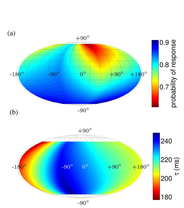
school. Visual cues such as an approaching predator can elicit                  C. Three-dimensional tracking
a startle response whether the cue is observed or not. The                         Tracking the three-dimensional position and orientation
visual fields of fish play an important role in predator-prey                   of the fish is required to present the stimulus to the fish.
interactions and, presumably, shoaling behavior. Despite the                    Tracking objects in three dimensions using cameras is a well-
importance, visual fields of fishes have only been investigated                 researched problem [21], [22]. Each application motivates a
in several fish species (see [17] for a review) and have                        different camera arrangement [23], [24], [25], but the basic
not been characterized for a group of animals, including                        approach stays the same. A single-camera system is attractive
fishes. This paper expands on that work by behaviorally                         since the data can be processed in real-time without the
characterizing the receptive fields of Giant danios through                     need to synchronize between multiple views. Since a single
the use of virtual reality.                                                     camera may be unable to observe the three-dimensional
   The use of a virtual-reality design with real-time sensory                   position of an object, techniques that solve this problem
feedback also enables the manipulation of a stimulus or scene                   include model-based tracking [21] and obtaining another
during a trial without experimenter intervention, and provide                   perspective from a mirror [23] or shadows [26]. Real-time
a natural stimulus display. The use of natural stimuli is                       tracking capabilities depend on the frame rate, processing
common for understanding a variety of sensory systems [18],                     power, and the amount of data to be processed in each frame.
[19]. These studies and many more have helped demonstrate                          In a target-tracking framework, the state of a target at time
the dynamic properties of sensory neuronal systems and have                     k is described by the vector X k ∈ Rn . A measurement
led to hypotheses on how these systems may be optimized.                        at time k is denoted by Z k ∈ Rm . The state X k+1 and
B. Virtual-reality setup                                                        measurements Z k+1 are related to the state X k according
                                                                                to
   The virtual-reality setup we use in our experiments com-
prises a single looming stimulus that approaches the viewer                                      X k+1 = F (X k , wk+1 )
                                                                                                                                            (1)
from a distance. The stimulus in our experiments is an on-                                       Z k+1 = H(X k+1 , nk+1 ),
screen representation of a three-dimensional moving object.
                                                                                where F represents the motion model, H represents the
The threat presented by a looming stimulus depends on its
                                                                                measurement model, and w and n are the instantaneous
size, speed, and direction of motion. The perspective of the
                                                                                disturbance- and measurement-noise values. Given the state
viewer determines how the object is presented on a computer
                                                                                estimate X̂ k , estimation error X̂ k − X k occurs due to
screen. To represent the view on the computer screen we
                                                                                noise and approximation in F and H. The conditional
assume a perspective-projection model, i.e., an object appears
                                                                                probability of state X k given the measurements up to time
larger as it gets closer. A limitation of the virtual-reality setup
                                                                                k, Z k , is called the posterior probability density function
described here is that the scene is set for only one subject at
                                                                                (pdf), denoted by p(X k |Z k ). An optimal Bayesian solution
a time. This limitation is in part due to the large perceptual
                                                                                recursively maximizes the posterior pdf. In the case when (1)
range of fish visual field [20] as well as size of the screen.
                                                                                is linear and w and n are Gaussian white noise, a Kalman
   Fig. 1 shows a schematic of the test environment. Let
                                                                                filter gives the optimal estimate.
I be the inertial reference frame, V be the viewer frame
and S be a frame fixed to the stimulus. The position t ∈                           III. I MMERSIVE VR FOR BEHAVIOR EXPERIMENTS
R3 and orientation R ∈ SO(3) of a reference frame is                               This section describes the generation of a moving stimulus
represented
             inanother frame by a 4×4 transformation matrix                   on the computer screen as well as the setup for computing
        R t
T =              . Let I TV represent the configuration of the                  the three-dimensional pose and velocity of a viewer in real-
        0T 1                                                                    time using a single camera.
viewer frame in the inertial frame and I TS represent the
configuration of the stimulus frame in the inertial frame.                      A. Looming stimulus
The stimulus in the viewer frame is V TS = V TI I TS , where                       We present a specific type of stimulus called a loom-
V
  TI = (I TV )−1 .                                                              ing stimulus, which gives the appearance of an object ap-
                                                                                proaching the viewer from a distance. Since we assume a
                                                                                perspective-projection model for the fish, the stimulus size
                                    I                                           increases as it gets closer. We produce the stimulus on a
         x
  S
                                x   z                                           computer monitor placed to the side of a fish tank.
         z                                      x
                                                                                   In addition to size, the looming stimulus will also change
                        h                                                       shape according to the perspective of the viewer. We use line
                                        a
                 x                          z                                   of sight to define the perspective of the viewer. The line of
             z                                      V
                 L                                                              sight may be different than the head orientation. We choose
                                                                                among the following ways to update the perspective of a
                                                                                viewer as a stimulus moves (Fig. 2): (1) set it at the center
                                                                                of the stimulus; (2) center it between the stimulus and the
                                                                                screen; and (3) center it on the screen. In human virtual-
Fig. 1. Reference frames V (viewer), S (stimulus), L (screen) and I             reality applications, the perspective is often centered on the
(inertial). The azimuth (a) and elevation (h) of the stimulus with respect to
the fish are also shown.
Fig. 2. A looming circular disc with different colored faces (red and blue) as it appears to the viewer: (left) looking at the disc, (middle) looking between
the disc and the center of the screen, and (right) looking at the center of the screen.
Angular retinal image (rad)
screen because the viewer head pose is tracked [13]. For a 2.5
1.5
looming stimulus, however, the perspective changes as the 2
size (m)
stimulus moves on the screen. 1 1.5
The azimuth and elevation of an approaching stimulus 0.5
1
0.5
are based on the viewer’s pose (see Fig. 1). The azimuth
−180◦ ≤ a ≤ 180◦ , is the horizontal angle measured 0 1 2
time (s)
3 4 0 1 2
time (s)
3 4
clockwise from the line between the viewer position and
the projection of the viewer on the computer screen. The Fig. 3. (Left) Stimulus size for different types of motion: constant velocity
(dashed red), constant acceleration (solid green), and constant jerk (blue
elevation −90◦ ≤ h ≤ 90◦ , is the angle between the stimulus dots). (Right) Corresponding change in angular retinal image size [7].
and the horizontal plane. Due to the instantaneous viewer
pose and screen size, the full range of azimuth and elevation
B. Three-dimensional real-time tracking using a mirror
may not be available to present the stimulus. Instead, with
our real-time tracking system, the stimulus is conditionally We use the three-dimensional estimate of the fish pose
presented based on the current viewer pose. to create an accurate representation of the stimulus at a
The size of the stimulus on the screen is computed as given position on the screen. To obtain the three-dimensional
follows: given the real-world size sd of the stimulus, the estimate we need multiple views of the scene, so we mount a
distance dvs between the viewer and the stimulus center, and mirror on the side of the tank to obtain a second perspective.
the distance dvl between the viewer and the screen along the The view from the mirror is calibrated as a left-handed
line of sight, the screen dimension sl for the stimulus is camera system. Since the overhead view and the reflection
sd of the side of the tank is viewed from the same camera, we
sl = dvl . (2) extract the three-dimensional estimate from a single frame.
dvs
Each view within a frame is defined by a preset region of
Equation (2) is similar to a perspective-projection model interest. To compute position, we project the head of the fish
equation except that dvl and dvs vary as the stimulus moves. in the top view onto a line in the side view [28]. The head
(dvl does not change when the perspective is fixed or when in the overhead view is marked as the center of the largest
the stimulus approaches the viewer along the line of sight.) circle to fit within the top-view silhouette. (The centroid of
Taking the derivative of (2), we find the change in size of the silhouette marks the body of the fish.) The pitch of the
the stimulus on screen as a function of time: fish is found by the slope of the line that fits the side-view
sd sd ˙ silhouette (in the mirror) in a least-squares sense. We use
ṡl = −d˙vs 2 dvl + dvl
dvs dvs three constraints—two from projecting the estimate on the
sl sd ˙ (3)
= −d˙vs + dvl . overhead view, and one from fitting the projected estimate to
dvs dvs the line on the side view—to estimate the three-dimensional
Fig. 3 shows stimulus size as a function of time for constant position of the head and body.
acceleration and constant jerk (rate of change of accelera- The estimate represents an input measurement to a Kalman
tion). A related optical parameter θ called angular retinal filter with measurement noise values based on experimental
image size [27], [7] may also be used to study the effects of data collected by tracking rigid known-sized objects. The
the looming stimuli. The angular retinal image size is related filter state estimate X ∈ R6 consists of the three-dimensional
to the size sd of the stimulus according to position and velocity of the head. Fish motion F is modeled
as constant velocity with Gaussian disturbance, and H =
sd sl I 3 03 , where I 3 and 03 denote the 3 × 3 identity and
θ = 2 tan−1 = 2 tan−1 . (4)
2dvs 2dvl zero matrices. Fish heading is computed instantaneously as
the three-dimensional vector between the body and the head.
Variability in the appearance of a looming stimulus are We make two assumptions regarding fish movement and
introduced in terms of the starting and stopping position of pose: (1) the fish head in our experiments is oriented in the
the stimulus, its size, and dynamics. direction of motion, and (2) the fish in our experiments turnand pitch but rarely roll. We validate the first assumption Camera
prior to presenting the stimulus by comparing the velocity
vector with heading. Based on the second assumption we use
the true vertical to compute the full fish pose [28]. Screen
A common problem associated with tracking within a glass
tank is extraneous measurements arising due to reflections on
the air-glass interface. Given a calibrated stereo camera pair,
a measurement correspondence between the two views must
satisfy the epipolar constraint [29]. We check the epipolar
constraint for every combination of measurements within two
views to filter out measurements caused by reflections.
IV. E XPERIMENTAL R ESULTS
A. Materials and methods Mirror
Fishtank
Giant danio 4–6 cm in body length were maintained in
a 208 litre (55 gallon) tank, with approximately 45 fish in Fig. 4. Experimental setup
the tank at 30◦ C (83◦ F) on a 14 hours light / 10 hours dark
photoperiod. Filtered and de-ionized water was provided by
a pump system. Water quality was monitored regularly and
was the same for experimental tanks.
The experimental setup consists of a 0.5 m × 0.25 m
× 0.30 m (20"×10"×12"), 37.8 litre (10 gallon) tank.
The tank was backlit using diffused (1/4 stop) upwelling
light from two 42 Watt lamps facing the floor and the wall
opposite the mirror to create a uniform background. The fish
did not exhibit aversive behavior to lighting conditions.
A 20" screen for presenting the stimuli was set on one side
of the tank at a resolution of 800 × 600 pixels and 60 Hz
refresh rate. The video input to the screen was duplicated to a
second 8" screen that was installed facing up so that it could
be used for verification. We used a MicrosoftTM Cinema Fig. 5. View from a second camera for verification (see attached video).
Lifecam at 640 × 480 pixel resolution mounted above a
fish tank looking straight below. A mirror was mounted at
B. Behavioral experiments
an angle to the side of the tank as shown in Fig. 4. Intrinsic
calibration was performed in air using a checkerboard and the It is currently unknown what information fish extract from
MATLABTM calibration toolbox [30]. Extrinsic calibration a looming stimulus. Evidence suggests that it may be a
was performed by immersing the checkerboard in water in combination of optical parameters [7] one of which is the
view of the camera as well as the mirror. (The mirror was time-to-collision. Time to collision, τ , is the time it would
angled at 30◦ to the tank surface.) The reprojection error for take the stimulus to reach the fish head. For small angles and
each camera view was in subpixels. Reconstruction error of a constant-velocity stimulus τ = θ/θ̇ [27]. Given an initial
0.82 ± 0.59 mm was determined empirically by triangulating stimulus velocity and acceleration, we compute the value of
60 pairs of points ranging between 30 and 150 mm apart at τ based on the separation distance between the fish and the
various locations within the tank. This error, which is due to stimulus. We were unable to record eye movements, so the
refraction from the air-water interface, is small because of stimulus was presented based on fish pose.
the relatively small working volume [31]. Absolute position We performed separate experiments to demonstrate the
error of 1 cm was verified by projecting the position of a effectiveness and measure startle sensitivity. In the first
static object at various positions on the computer screen. experiment we presented the stimulus head-on to 4 different
Threshold-based background subtraction from the first fish at random intervals and locations within the tank. This
frame in each sequence was performed to isolate the fish experiment served to validate the setup as well as to provide
in the region of interest for each camera view. The tracking a method to detect startle responses automatically for the
algorithm (running at 15 Hz) and looming stimulus (pre- second experiment. In the second experiment 39 fish were
sented at 60 Hz) were implemented in MATLAB using the presented an approaching stimulus from eight equally spaced
Image Acquisition Toolbox. Fig. 5 shows images from a regions around its head. The order of the regions and position
second camera used for independent verification of tracking within each region was sampled randomly. We describe
and positioning of the stimulus with respect to the fish. below each of these experiments and the parameters usedto perform the trials. presentations were not uniform (167 from the top and 100
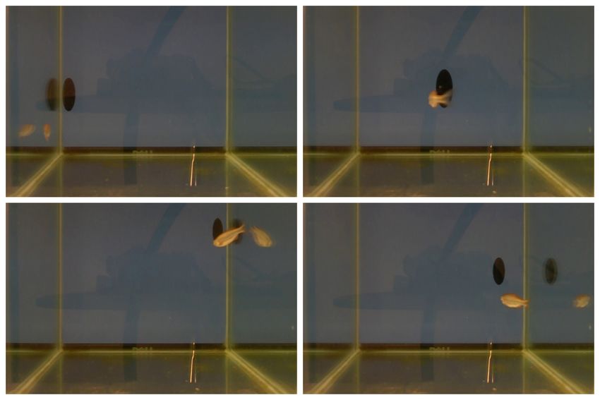
Experiment #1: Effectiveness of VR setup We measured from the bottom), due to tank size and the fact that the fish
success in eliciting a startle response in freely roaming fish exhibited a preference for the bottom of the tank.
by presenting the stimulus head-on at random locations in the Fig. 6(a) shows the probability of a startle response
tank, and used fish acceleration to identify a startle response. calculated by taking the number of startle instances in a
A stimulus was presented head-on every time the fish region divided by the total number of stimulus presentations
moved towards the screen (−5◦ ≤ h ≤ 5◦ and −5◦ ≤ a ≤ in that region. Response probabilities varied between the
5◦ ). For each presentation of the stimulus, we determined eight regions, from 58% (slightly above chance levels) in
whether a startle occurred and if so, the value of τ in the the upper right front region to 94% in the back lower left
frame when the startle was detected. Trials consisted of region. When the data from separate regions was pooled, the
presenting the stimulus to four different fish. Each session probability of response to the front and to the right was 76%
consisted of eight trials with a ten-minute habituation period and the response probability to the back and the left was
and a randomized inter-trial interval of two to five minutes. 80%.
The stimulus was started 50 cm away from the fish with an Fig. 6(b) shows the startle sensitivity map for each fish as
initial velocity of 100 cm/s and a constant acceleration of a Mollweide (equal area) map projection. A total of 176 data
100 cm/s2 . The stimulus was an ellipsoid with axis lengths points were selected out of 267 based on the threshold on
of 20 cm, 10 cm and 4 cm.1 acceleration. Although the mean ranks did not differ between
Experiment #2: Investigation of startle response to VR the eight regions (p=0.3209, Kruskal-Wallis test), the fish
stimuli The purpose of the second experiment was to measure appear to respond two body lengths sooner (80 ms) to a head-
the response kinematics and sensitivity of the giant danio as on stimulus as compared to the ones coming from behind or
a function of orientation of a directed stimulus. The ultimate above.
goal is to use this information to selectively startle a few
fish in a school. We predicted that the fish has a lower
probability of responding to a visual threat from behind.
To test this prediction, the sphere around the fish head was
divided into eight equal sections of 90◦ azimuth and 90◦
elevation. One section was randomly selected at the start of
the trial and the fish tracked until the required azimuth and
elevation range was reached. The stimulus was presented at
a random location within that section. Trials consisted of a
twenty-minute habituation period and randomized inter-trial-
intervals of three to nine minutes. Fish pose and velocity
were validated at each timestep to ensure that (1) the fish
heading and direction of motion was aligned (2) the fish was
moving at a speed less than 150 cm/s (3) the fish was more
than one body length away from the tank walls. Stimulus
properties were the same as in Experiment #1.
C. Results & Discussion
In Experiment #1, the success rate of eliciting a startle
response in fish for an oncoming stimulus was 94% (30/32).
Previous work in our laboratory with non virtual-reality
stimuli resulted in about 30%–50% probability of response.
Startle responses were verified visually. The fish acceleration
during a startle ranged between 200–657 cm/s2 . (Values lying Fig. 6. (a) Probability of response and (b) mean value of time-to-collision
within this range in Experiment #2 were marked as startle (τ ) interpolated between 90◦ azimuth and 90◦ elevation sections of the
stimulus onset in the fish head frame for startle responses. The point (0,0)
responses automatically.) The average time to collision for a marks the front of the fish, (0,90) is above the fish head and (±180,0) is
head-on stimulus was 317 ± 45 ms. behind the fish.
In Experiment #2, we investigated the startle response of a
We also recorded the trajectory of the individual fish
fish based on the directionality of a three-dimensional stim-
away from the stimulus. Fig. 7 shows that greater number
ulus. A total of 267 stimulus presentations were recorded.
of responses move between 120◦ –180◦ away from a threat.
The stimulus was presented uniformly from the left and
Average change in depth was 30 ± 26 mm from the fish
right hemispheres of the fish (133 from the left and 134
start position.
from the right). For the top and bottom hemisphere, the
V. C ONCLUSION
1 Allprocedures were done according to protocol R 11-53 ”Quantitative
Analysis of Schooling Behavior” approved by the University of Maryland, We describe a novel virtual-reality framework to under-
College Park Institutional Animal Care and Use Committee. stand information transmission during an escape behavior90 50 [8] D. Oliva, V. Medan, and D. Tomsic, “Escape behavior and neuronal
120 40 60 responses to looming stimuli in the crab Chasmagnathus granulatus
30 (Decapoda: grapsidae),” J. of Exp. Biology, vol. 210, no. 5, 2007.
[9] J. Chen and H. Lee, “Application of virtual reality environment for
150 20 30 studying rats cognitive behavior,” Proc. of World Conf. on Educational
10 Multimedia, pp. 4201–4207, 2007.
[10] A. D. Straw, K. Branson, T. R. Neumann, and M. H. Dickinson,
“Multi-camera real-time three-dimensional tracking of multiple flying
180 0 animals,” J. Royal Society Interface, vol. 8, no. 56, pp. 395–409, 2010.
[11] H. Lee, R. Cherng, and C. Lin, “Development of a Virtual Reality
Environment for Somatosensory and Perceptual Stimulation in the Bal-
ance Assessment of Children,” Computers in Biology and Medicine,
210 330 vol. 34, no. 8, pp. 719–733, 2004.
[12] A. Ward, “Quorum decision-making facilitates information transfer in
fish shoals,” Proc. of the Nat. Academy of Sciences, vol. 105, no. 19,
240 300 pp. 6948–6953, 2008.
270 [13] J. Rekimoto, “A vision-based head tracker for fish tank virtual reality-
VR without head gear,” in IEEE International Sym. on Virtual Reality,
Fig. 7. Circular frequency distribution of escape trajectories of giant danio 1995, pp. 94–100.
defined as the mean swimming direction of the fish twenty frames after a [14] J. Mulder and R. Van Liere, “Enhancing fish tank VR,” in Proc. of
startle response with respect to stimulus orientation at rest. The stimulus is Virtual Reality, 2000, pp. 91–98.
approaching from 0◦ towards the center. Each concentric circle represents [15] R. Eaton and D. Emberley, “How stimulus direction determines the
a frequency of 10. trajectory of the Mauthner-initiated escape response in a teleost fish,”
Journal of experimental biology, vol. 161, no. 1, p. 469, 1991.
in fish, which is an important communication strategy in [16] H. Korn and D. Faber, “The Mauthner cell half a century later: a
multi-agent robotics. We use the setup to investigate a fish’s neurobiological model for decision-making?” Neuron, vol. 47, no. 1,
response to visual cues in a free-swimming environment. pp. 13–28, 2005.
[17] G. Walls, The Vertebrate Eye and its Adaptive Radiation. Cranbrook
A looming stimulus, one that approaches the fish from a Institute of Science, 1942.
distance and grows in size, is used to validate the setup. The [18] A. Sichert and J. van Hemmen, “How stimulus shape affects lateral-
setup is fully automated and allows collection of high-volume line perception: Analytical approach to analyze natural stimuli charac-
teristics,” Biological Cybernetics, vol. 102, no. 3, pp. 177–180, 2010.
datasets without any human intervention. Two experiments [19] R. Herikstad, J. Baker, J. Lachaux, C. Gray, and S. Yen, “Natural
were performed to demonstrate its effectiveness. We demon- movies evoke spike trains with low spike time variability in cat primary
strate the success in eliciting a startle response by presenting visual cortex,” J. of Neuroscience, vol. 31, no. 44, pp. 15 844–15 860,
2011.
the stimulus to 39 individual fish from different orientations. [20] S. Hall, C. Wardle, and D. MacLennan, “Predator evasion in a fish
The startle sensitivity map allows us to tune the stimulus school: test of a model for the fountain effect,” Marine Biology,
speed and size for targeting specific fish within a school. vol. 91, no. 1, pp. 143–148, 1986.
[21] V. Lepetit and P. Fua, “Monocular model-based 3D tracking of rigid
Such an approach, for example, would highlight the role of objects: a survey,” Foundations and Trends in Computer Graphics and
individual sensory modalities in a manipulative experiment Vision, vol. 1, no. 1, pp. 1–89, 2005.
where a specific number of fish are selectively targeted. [22] A. Yilmaz, O. Javed, and M. Shah, “Object tracking: A survey,” ACM
Computing Surveys (CSUR), vol. 38, no. 4, pp. 1–45, 2006.
[23] C. Wehrhahn, “Tracking and chasing in houseflies (Musca),” Biologi-
VI. ACKNOWLEDGMENTS cal Cybernetics, vol. 45, pp. 123–130, 1982.
The authors would like to thank Jennifer Lun for her [24] N. F. Hughes and L. H. Kelly, “New techniques for 3-D video tracking
of fish swimming movements in still or flowing water,” Canadian J.
work on the probability of startle response with a non of Fisheries and Aquatic Sciences, vol. 53, no. 11, pp. 2473–2483,
virtual-reality stimulus. This material is based upon work Nov. 1996.
supported by the National Science Foundation under Grant [25] S. V. Viscido, J. K. Parrish, and D. Grünbaum, “Individual behavior
and emergent properties of fish schools: A comparison of observation
No. CMMI0954361. and theory,” Marine Ecology Progress Series, vol. 10.3354/me, pp.
239–249, 2004.
R EFERENCES [26] B. J. Laurel, C. J. Laurel, J. A. Brown, and R. S. Gregory, “A new
technique to gather 3D spatial information using a single camera,” J.
[1] F. Gerlotto, S. Bertrand, N. Bez, and M. Gutierrez, “Waves of agitation of Fish Biology, vol. 66, pp. 429–441, 2005.
inside anchovy schools observed with multibeam sonar: a way to [27] N. Hatsopoulos, “Elementary computation of object approach by a
transmit information in response to predation,” ICES J. of Marine wide-field visual neuron,” Science, vol. 270, pp. 1000–1002, 1995.
Science, vol. 63, no. 8, pp. 1405–1417, 2006. [28] S. Butail and D. A. Paley, “Three-dimensional reconstruction of the
[2] R. Arkin, Behavior-based robotics. MIT Press, 1998. fast-start swimming kinematics of densely schooling fish,” J. Royal
[3] A. Jadbabaie, J. Lin, and A. S. Morse, “Coordination of groups of Soc. Interface, vol. 9, no. 66, pp. 77–88, 2011.
mobile autonomous agents using nearest neighbor rules,” in IEEE [29] R. Hartley and A. Zisserman, Multiple View Geometry in Computer
Trans. on Automatic Control, vol. 48, no. 6, 2003, pp. 988–1001. Vision. Cambridge University Press, 2004.
[4] D. A. Paley, N. E. Leonard, R. Sepulchre, D. Grunbaum, and J. K. [30] J.-Y. Bouguet. Camera Calibration Tool-
Parrish, “Oscillator models and collective motion,” IEEE Control box for Matlab. [Online]. Available:
Systems Magazine, vol. 27, no. 4, pp. 89–105, 2007. http://www.vision.caltech.edu/bouguetj/calib doc/index.html
[5] H. Min and Z. Wang, “Design and analysis of Group Escape Behavior [31] V. Gourgoulis and N. Aggeloussis, “Reconstruction accuracy in un-
for distributed autonomous mobile robots,” in Int. Conf. on Robotics derwater three-dimensional kinematic analysis,” J. of Science and
and Automation. IEEE, 2011, pp. 6128–6135. Medecine in Sport, vol. 11, no. 2, pp. 90–95, 2008.
[6] R. Santer, P. Simmons, and F. Rind, “Gliding behaviour elicited by
lateral looming stimuli in flying locusts,” J.of Comparative Physiology
A, vol. 191, no. 1, pp. 61–73, 2005.
[7] T. Preuss, P. E. Osei-Bonsu, S. A. Weiss, C. Wang, and D. S. Faber,
“Neural representation of object approach in a decision-making motor
circuit,” J. of Neuroscience, vol. 26, no. 13, pp. 3454–3464, 2006.You can also read