Quality Control of Headphones
←
→
Page content transcription
If your browser does not render page correctly, please read the page content below
Quality Control of Headphones                                                                      AN73
Appli cati on Note for the KL IPP EL ANALYZ ER S YSTEM
Docum ent Revi si on 1 .4

SCOPE
    •    Fast and reproducible quality con-
         trol in lab or end of production line
    •    Over- and on-ear headphones and
         headsets (also applicable to ear-
         phones)
    •    Passive, digital (USB) and wireless
         devices (Bluetooth® wireless tech-
         nology enabled products)
    •    Microphone test
    •    Noise attenuation (passive or ANC)
    •    KLIPPEL QC software framework
         (also available in R&D framework)
    •    KLIPPEL Analyzer 3 or Production
         Analyzer
    •    G.R.A.S. 45CC headphone test fix-
         ture dedicated to quality control

OVERVIEW
Testing head- and earphones can be a challenging and time-consuming task that requires experience and care-
ful handling in order to obtain meaningful and reproducible results. In an R&D context, such tests are covered
by various standards (e.g. IEC 60268-7) and a multitude of dedicated test fixtures including ear and mouth simu-
lators are available on the market for this purpose. Ear (as well as head and torso) simulators are used to pro-
vide a defined acoustical load and expected target response at the ear-drum reference point (DRP) according to
ITU-T P.581.
However, such design-related testing approaches are hardly applicable in high-volume quality control. Other
requirements like simple handling, speed, stability, robustness against ambient noise and reproducibility are
much more important in end-of-line testing following the ultimate goal of distinguishing good from bad units
reliably.
This application note focuses on those requirements and provides approaches for testing various types of
headphones and headsets exploiting the features and flexibility of the KLIPPEL QC Software framework, Klippel
Analyzer hardware and the G.R.A.S. 45CC headphone test fixture dedicated to headphone quality control.
Out of many possible test scenarios, three different use cases are addressed
 • passive headphone,
 • digital USB headset,
 • Bluetooth® enabled headphone with active noise control (ANC).
Focusing on the challenges of testing digital and wireless devices, topics like connectivity, solutions for handling
different audio devices and dealing with unknown and varying playback delays are provided.
Other test scenarios may be derived based on the information provided. The suggested approaches may also be
applied to earphones using other dedicated test fixtures.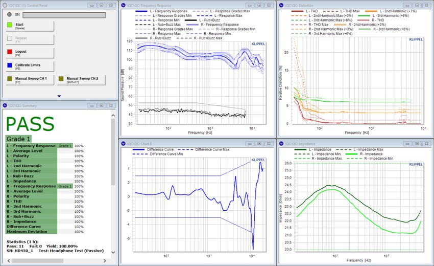
Quality Control of Headphones                                                                                                  1 Overview                AN73
CONTENT
1     Overview................................................................................................................................................................. 2
2     Passive Headphone ................................................................................................................................................ 3
3     Digital Headset (USB) ............................................................................................................................................. 9
4     Bluetooth Enabled Headphone with ANC .......................................................................................................... 14
5     Preparation ........................................................................................................................................................... 19
6     Requirements ....................................................................................................................................................... 22
7     Further Topics ...................................................................................................................................................... 24
8     References ............................................................................................................................................................ 28
9     Appendix ............................................................................................................................................................... 30

1     Overview

1.1     How to Use this Application Note
                            This document addresses three particular test scenarios for different types of headphones
                            and headset in detail. Pick one of the use cases that corresponds best to the device under
                            test and continue with the corresponding chapter:
                             • Passive Headphone
                             • Digital Headset (USB)
                             • Bluetooth Enabled Headphone with ANC
                            Before starting with practical testing, it is recommended to read the hard- and software
                            Requirements and follow the instruction given in section Preparation carefully.
                            Some continuative topics related to headphone testing are addressed in section Further
                            Topics.

1.2     Results
                            In QC, the goal is to provide critical and meaningful test parameters to ensure consistent
                            product quality and specification sheet compliance translated to the EOL test:
                            Headphone parameters
                                • Frequency response of left and right channel
                                • Sensitivity (average or single frequency level)
                                • Inter-channel difference (left-right balance)
                                • Polarity
                                • Harmonic distortion (THD, 2 nd, 3rd, ...)
                                • Rub & buzz distortion
                                • Impedance magnitude (for passive DUTs)
                                • Minimal impedance (for passive DUTs)
                            Microphone parameters (headset)
                                   •      Frequency response
                                   •      Sensitivity
                                   •      Harmonic distortion (THD)
                                   •      Opt: noise/impulsive distortion (Rub & Buzz)
                            Attenuation
                                   •      Sound attenuation over frequency (passive or ANC)
                            A detailed discussion of the results is done in the application sections.

KLIPPEL Analyzer System                                                                                                                                      Page 2 of 31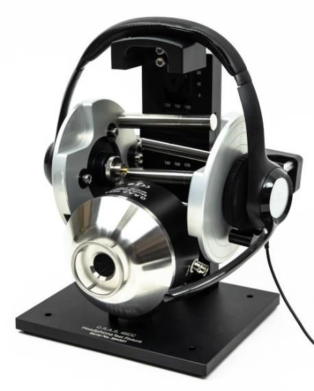
Quality Control of Headphones                                    2 Passive Headphone        AN73
                  The following example screenshot shows the operator view for a passive headphone test
                  realized with the KLIPPEL QC Standard software.

                                              Frequency Response

                                                                                 Harmonic Distortion
                                               Rub&Buzz

                                             L-R Difference                   Impedance Magnitude

2     Passive Headphone

2.1    Overview
               This application deals with testing analog stereo head-
               phones with 3.5 mm or 6.35 mm TRS phone connector
               focusing on impedance test, frequency response, channel
               difference, distortion and rub & buzz.
               It is a standard closed loop test setup where the KLIPPEL
               Analyzer is both playback (test signal) and input device
               (microphone input).
               The test fixture used here is the G.R.A.S. 45CC-2 without
               ear simulator. The RA0039 may be added to provide stand-
               ardized acoustical load conditions to the DUT.
               Follow the steps in section Preparation carefully before
               starting with this section.

2.2    Hardware Setup
For general hardware requirements and necessary components refer to section Hardware.

KA3 with       The sketch below visualizes the typical setup for passive headphone testing using KA3 hard-
Amplifier      ware. Please read section Connecting Passive Stereo Headphones carefully before continuing.
Card

KLIPPEL Analyzer System                                                                       Page 3 of 31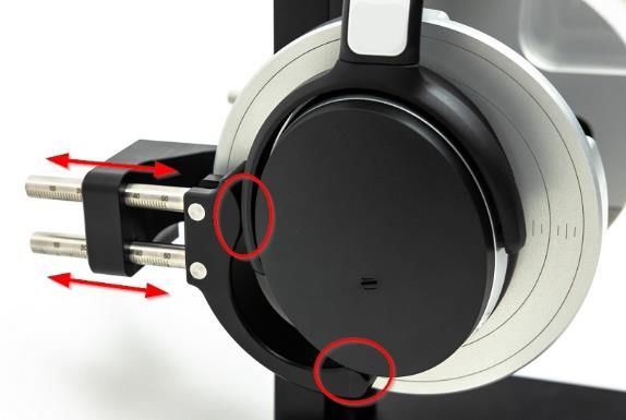
Quality Control of Headphones 2 Passive Headphone AN73
PASS K LIP
11
0 P EL
10
0
9
Ambient Noise 0
8
SoundPressure [dB]
0
7
Mic (opt.) 0
6
0
5
0
4
0
3
0 1 1 1
2 Frequenc3 4
0 0 0
y [Hz]
DUT
PC
1 2
Mics
3.5 mm
connector 1+/2+ and 1-/2-
bridged
Test Fixture
Laser Card XLR Card Speaker Card
FU SE FU SE
FU SE FU SE
XLR-BNC
Adaptor
KLIPPEL Analyzer 3 (front) Amplifier Card AMP-OUT
Ch 1
(1+ and 1-)
KLIPPEL Analyzer 3 (back)
• Connect the KA3 to the PC using the USB cable provided by KLIPPEL
• Connect the Amplifier Card output to the AMP input of the Speaker Card (mind correct
orientation of mono cable with one-sided bridge
Attention: The standard four-wire stereo speakON amplifier cable provided by KLIP-
PEL is not suitable for driving headphones with common ground with stereo class D
amplifiers. However, it may be used after modification for mono operation.
• Connect the headphone jack to the outputs SP1 and SP2 of the Speaker Card using the
custom adaptor cable
• Connect the microphones of the test fixture to IN3 and IN4 of the Laser Card
• Optional: connect the ambient noise microphone to IN1 of the XLR Card (use an XLR-BNC
adaptor for microphones with IEPE supply)
Production The setup described above may be realized with the PA hardware in a similar way using an
Analyzer with external headphone amplifier and an optional IEPE mic supply in order to use 3 microphones
External Am- in total (ambient noise), one connected to the Line input of the analyzer.
plifier
KLIPPEL Analyzer System Page 4 of 31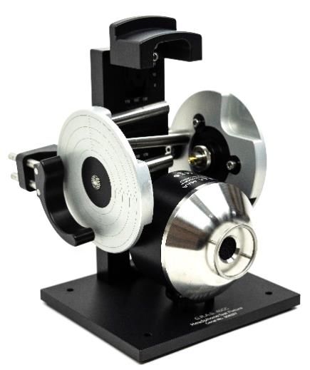
Quality Control of Headphones                                                                      2 Passive Headphone                         AN73
                                                                                DUT

                                                                                                                          PC

                                                        Mics

                                                                                                         3.5 mm
                                                                                                        connector

                                              Test Fixture

                                                                         KLIPPEL Production Analyzer (front)

                                                                                  Production Analyzer
                                                                                                                          1+/2+
                          OUT1   OUT2    MIC1 LINE1 LINE2 MIC2
                                                                                                                        and 1-/2-
                                                                                                                         bridged
                                                                 KLIPPEL Production Analyzer (back)

                                                                                              POWER        USB   DIGITAL I/0   AMP SPEAKER 1 SPEAKER 2

                                          1    1
                                                                       Headphone Amplifier

                          Amp In (L+R)   Amp Out (2 x TRS Stereo)

                   •       Connect the PA to the PC using the USB cable provided by KLIPPEL (not displayed)
                   •       universal stereo audio amplifier (not displayed)
                           o set the amplifier to stereo or parallel mode
                           o connect PA OUT1 to the amplifier input 1
                           o connect single channel amplifier output to the AMPLIFIER input of the PA; the 2+
                                and 2- amplifier cable wires must be connected to 1+ and 1-
                   •       headphone amplifier (e.g. Lake People F388 S)
                           o Connect both outputs OUT1/2 of the PA to the stereo inputs of the headphone
                                amplifier
                           o Connect the stereo output of the amplifier to the AMPLIFIER input of the PA (cus-
                                tom amplifier cable 3 pole jack to NL4 speakON provided by Klippel)
                   •       Connect the headphone jack to the outputs Speaker 1 & 2 outputs of the PA using the
                           custom adaptor cable
                   •       If no ambient noise microphone is used, connect the microphones of the test fixture
                           to MIC1 and MIC2 of the PA as displayed
                   •       Otherwise:
                           o connect the first microphone of the test fixture to MIC1 input of the PA
                           o connect the second test fixture microphone to the external microphone sup-
                                ply/preamp (activate 10 dB boost if available)
                           o connect the output of the supply IN1 of the XLR Card (use an XLR-BNC adaptor
                                for microphones with IEPE supply)
                           o Note: it is necessary to calibrate the whole signal chain with a sound calibrator,
                                especially when an additional gain stage is used
                           o connect the ambient noise microphone of the test fixture to MIC2 input of the PA

2.3   Test Sequence
               Several test templates for passive headphones are provided with this application note or your
               KLIPPEL software. Create a new test based on the template Passive Headphone or Passive
               Headphone (Fast) and login via QC Start Engineer or open the database and press the green
               arrow in the task bar.

KLIPPEL Analyzer System                                                                                                                            Page 5 of 31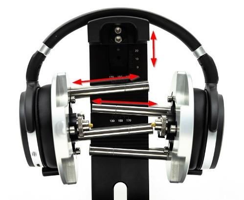
Quality Control of Headphones                                              2 Passive Headphone          AN73
Passive         This test sequence contains 5 tasks for testing sound
Headphone       pressure response (audio range) and impedance indi-
                vidually for left and right channel. Difference is a post-
                processing task that calculates the deviation between
                the fundamental frequency response of both channels.
                Note: Executing this sequence requires a QC Standard license
                due to the number of tasks. For QC in R&D framework, the
                sequence may be split into two separate operations (Imped-
                ance, Sound Pressure + Diff) to handle the restriction of 3 tasks
                per test.
                Impedance tasks may be removed in case only acoustical parameters shall be measured.

Passive         The Fast version of the test sequence uses combined
Headphone       SPL+IMP task to measure both sound pressure and im-
(Fast)          pedance characteristic simultaneously with a single
                sweep signal.
                In case KA3 hardware is used, the Signal Data Sharing feature allows measuring both channels
                simultaneously for time critical testing. The option is active by default but may be deactivated.
                Note: The Difference task is not operable with QC Basic license. However, you may select and remove the
                task from the sequence.

2.4   Adjust Settings

Input Routing   Adjust the input routing (Test Sensor L/R as well as opt. Noise Sensor) of the Sound Pressure
                tasks according to the actual analyzer and microphone setup used. The provided templates
                are preconfigured for use with KA3 and ambient noise microphone.

Voltage         For the Sound Pressure task, this parameter specifies the
                sinusoidal RMS voltage at the amplifier output considering
                the measured open-circuit gain of the amplifier (card).
                The voltage should be high enough to provide sufficient
                signal-to-noise ratio in the acoustic response as well as suffi-
                cient excitation for potential defect and distortion mecha-
                nisms. Test voltage may also be derived from standard val-
                ues as defined by IEC 60268-7 such as rated source e.m.f.,
                characteristic voltage (94 dB at 500 Hz) or 1 mW input pow-
                er equivalent voltage.
                Note: Parameter Level Profile can be used to boost the stimulus
                signal and thus improve poor SNR in certain frequency ranges.
                The EQA module may be used to automatically determine the char-
                acteristic voltage or to control the exact voltage at the DUT terminals under load conditions. Refer to
                section Adjusting Target SPL for more information.
                Attention: Most of the standard parameters require defined measurement conditions that are not fulfilled
                using test fixtures and other setups than specified in the standard.
                There are no general guidelines for the voltage setting of the individual impedance measure-
                ment (RMS voltage of multi-tone stimulus). A too low voltage may result in a noisy impedance
                magnitude. Nonlinear effects at higher voltages are usually less critical.

Frequency       The sound pressure measurement should cover at least the rated frequency range of the test-
Range           ed device. The default setting covers the standard audio range from 20 Hz to 20 kHz. Adjust
                Fmin or Fmax in the Stimulus properties of the Sound Pressure tasks, if required.
                For the left-right balance test (Difference task) it may be necessary to limit upper or lower
                frequency range in the Difference Curve limit settings.

Ambient         In the default settings of the test templates, ambient noise detection is activated. If you are
Noise           using QC Basic license or no ambient noise microphone is connected, deactivate this option.
Detection       If a PNI license is available, further ambient noise settings are available (e.g. Auto Repeat) that
                may be activated/configured. Refer to PNI Manual for more information.

KLIPPEL Analyzer System                                                                                   Page 6 of 31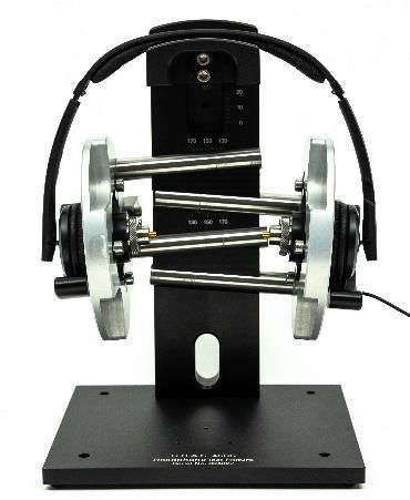
Quality Control of Headphones                                                                        2 Passive Headphone                        AN73
                For optimal performance, it is strongly recommended to measure the typical passive sound
                attenuation of the tested device mounted on the test fixture in order to replace the default
                setting “in Box Enclosure” assuming 15 dB attenuation. Refer to section Measurement of Am-
                bient Noise Attenuation for more information.

2.5   Results

Frequency       In the Frequency Response window, both channel’s (smoothed) fundamental frequency re-
Response        sponses are displayed. The curve colors can be edited in the task’s display settings in order to
                separate the left and right channel results visually.
                                            L - Frequency Response               L - Response Max                L - Response Min
                                            L - Rub+Buzz             L - Rub+Buzz Max               R - Frequency Response
                                              R - Response Max              R - Response Min               R - Rub+Buzz
                                              R - Rub+Buzz Max
                                      120
                                                                                                                                      KLIPPEL
                                      110

                                      100
                Sound Pressure [dB]

                                       90

                                       80

                                       70

                                       60

                                       50

                                       40

                                       30
                                                           10 2                             10 3                                    10 4
                                                                                Frequency [Hz]

                In this example, the limits for both channels differ because they are based on reference DUTs
                recorded in Limit Calculation Mode. Thus, systematic differences between both channels can
                be considered. In order to apply equal limits for both channels, absolute limit definition may
                be used (e.g. copy calculated curve of one channel and paste it as limit for second channel).
                Note: Normalized display modes are available to display the frequency response deviation from a golden
                reference unit, the reference average or relative to the Average Level. Also, floating limits are applicable
                to evaluate shape of the response curve instead of absolute level. Refer to QC User Manual for more
                information.

Rub & Buzz      Rub & Buzz reflects higher order, impulsive distortion as caused by most defects of the trans-
                ducer and other irregularities in the playback chain. The result curves for both channels are
                also plotted in Frequency Response window. In this example, absolute limits have been used
                that approximate the typical (shifted) noise floor of a typical reference unit. Relative (shifted)
                limits may also be applied, instead but will result in a less smooth curve.

Average Level   The single value result Average Level is derived from the measured Frequency Responses.
(Sensitivity)   Using default settings, it reflects the mean fundamental SPL in the complete measured fre-
                quency range. However, the frequency range may be restricted (or even limited to one fre-
                quency, e.g. 500 Hz) using property Average Level – Frequencies.

KLIPPEL Analyzer System                                                                                                                         Page 7 of 31
Quality Control of Headphones                                                                                                            2 Passive Headphone     AN73
L-R Balance    The Difference Curve reflects the spectral balance (deviation) between the Frequency
(Difference)   Responses of left and right channel, calculated by the Difference Task (post-processing). Both,
               the frequency-wise deviation and the maximal deviation may be tested.
                                                                                  Difference Curve
                                              Difference Curve                 Difference Curve Max               Difference Curve Min
                                                                                                                                            KLIPPEL
                                         4

                                         2

                                         0

                                         -2

                                         -4

                                                                 10 2                               10 3                                 10 4
                                                                                       Frequency [Hz]

               In this example, the tolerance has been slightly widened above 2 kHz and limited to frequen-
               cies lower than 10 kHz because the evaluation of high frequencies can be difficult and highly
               depends on modal transducer behavior and headphone positioning accuracy.
               Note: Difference task is not available for QC Basic license

Polarity       The polarity check is based on the acoustic phase response at low frequencies, relative to the
               phase of the reference units. This test is robust against small phase variation and detects
               wrong polarity (180° phase shift) reliably.

Harmonic       Relative harmonic distortion such as Total Harmonic Distortion (THD), 2nd and 3rd harmonic for
Distortion     left and right channel are displayed in result window Distortion. For visual separation, the 2 nd
               and 3rd order HD curves are shifted by 3 % and 6 % respectively. This can be adjusted or deac-
               tivated in the Display properties of the Sound Pressure task.
                                              L - THD              L - THD Max                   L - 2nd Harmonic (+3%)
                                                L - 2nd Harmonic Max (+3%)                  L - 3rd Harmonic (+6%)
                                                L - 3rd Harmonic Max (+6%)                 R - THD                R - THD Max
                                              R - 2nd Harmonic (+3%)                  R - 2nd Harmonic Max (+3%)
                                              R - 3rd Harmonic (+6%)                  R - 3rd Harmonic Max (+6%)
                                         12
                                                                                                                                                KLIPPEL

                                         10
               Relative Distortion [%]

                                          8

                                          6

                                          4

                                          2

                                          0
                                                           10 2                                            10 3                                           10 4
                                                                                         Frequency [Hz]

               Relative distortion may be calculated relative to isolated fundamental (IEEE) or total harmonic
               signal (IEC) as well as relative to average level in order to have less impact of peaks and dips in
               the frequency response.

Impedance      In result chart Impedance, the impedance magnitudes of the left and right channels are dis-
               played.
                                                 L - Impedance                       L - Impedance Max                     L - Impedance Min
                                                 R - Impedance                       R - Impedance Max                      R - Impedance Min
                                         26                                                                                           KLIPPEL

                                         25
               Impedance [Ohm]

                                         24

                                         23

                                         22

                                         21

                                         20
                                                                        10 2                                        10 3
                                                                                     Frequency [Hz]

               Absolute limits may be set up in a way that it is ensured that the nominal impedance is above
               80 % of the rated nominal impedance.
               The effective impedance magnitude of the complete headphone on the test fixture is often

KLIPPEL Analyzer System                                                                                                                                          Page 8 of 31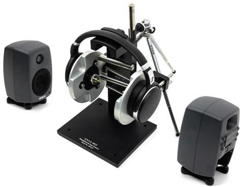
Quality Control of Headphones                                           3 Digital Headset (USB)       AN73
                  highly damped and may represent a complex electro-acoustic system. Therefore, Thiele-Small
                  transducer parameter measurement is not applicable, mostly. However, DC resistance (Re)
                  measurement or minimal impedance may be tested (see QC Manual - Impedance Values).

2.6    Limit Calculation

Relative Lim-     Since the whole test approach is dedicated to requirements of quality control, the result pa-
its (Golden       rameters are not necessarily evaluated on an absolute scale like standard conform results
DUTs)             obtained under normative conditions.
                  For this reason, a typical strategy for generating reasonable result parameter limits under QC
                  test conditions is based on approved reference DUTs (Golden DUT). Tested and verified under
                  lab conditions, one or more of these physical units are measured in the QC test station in or-
                  der to derive relative limits.
                  Alternatively, parameters such as Frequency Response may be normalized in order to monitor
                  the deviation from the reference unit. Other parameters (e.g. THD) can be measured relative
                  to the frequency response or average level.
                  The Golden DUT can be used to adjust limits in case of systematic drifts or changed conditions.
                  Find more information in QC User Manual sections Reference units, Limit Calculation or Golden Unit
                  Handling.

Identical         Since the left and right channels of the DUT are tested by separate QC Tasks, the limit calcula-
Limits for L/R    tion is independent for both channel’s responses. In order to use identical limits, absolute limit
Channel           definition can be used instead of relative shift that is based on the left and right channel’s
                  individually measured reference data.
                  Also, one or more identical reference responses may be imported that replace the recorded
                  reference DUTs for relative limit calculation.
                  Find more information in QC User Manual sections Absolute Limits or Limit Import.

3     Digital Headset (USB)

3.1    Overview
                 In contrast to passive headphones, digital headphones
                 usually do not provide a signal input or output for
                 direct test signal playback or microphone response
                 recording by the analyzer. Digital-analog conversion
                 and amplification is done by the active electronics
                 integrated in the headset. Only a digital interface is
                 provided, such as a USB interface.
                 This application focuses on testing both, the sound
                 pressure output and the microphone of a USB headset
                 that is accessible as a Windows audio device. This
                 requires two open-loop test operations executed in
                 batch run. The playback and recording device are
                 switched in both operations.
                 Since unknown delays are introduced by the D/A con-
                 version and sample buffers, the SYN add-on is used to
                 synchronize playback and capture using a unique syn-
                 chronization signal or even the stimulus itself.

3.2    Hardware Setup
For general hardware requirements and necessary components refer to section Hardware.

KLIPPEL Analyzer System                                                                                Page 9 of 31
Quality Control of Headphones                                                      3 Digital Headset (USB)                                        AN73
             The sketch below shows the typical hardware setup for a digital (active headset) with USB inter-
             face. In this example, the KA3 with Laser and XLR Card is used, but the Production Analyzer or an
             external sound card may be used instead.

                                                      Ambient Noise
                                                        Mic (opt.)
                                                                                              PASS                                                  K LIP
                                                                                                              11
                                                                                                               0                                    P EL
                                                                                                              10
                                                                                                               0
                                                               Headset                                         9
                                                                                                               0
                                                                                                               8

                                                                                                     SoundPressure [dB]
                                                                                       PC                      0
                                                                                                               7
                                                                                                               0
                                                                                                               6
                                                                                                               0
                                                                                                               5
                                                                                                               0
                                                                                                               4
                                                                                                               0
                                                                                                               3
                                                                                                               0          1                  1     1
                                                                                                                            2         Frequenc3      4
                                                                                                                          0                  0     0
                                                                                                                                       y [Hz]

                                                                                                                                1 2

                                                 Mouth                                      USB
                                                Simulator      Microphone
                                     Test Fixture

                                   Laser Card                     XLR Card

                                                                                                     FU SE                            FU SE
                                                                                                      FU SE                           FU SE

                                                                         XLR-BNC
                                                                         Adaptor

               •   Connect the analyzer to a free USB port of the PC using the USB cable provided by KLIPPEL
                   (avoid hubs or front USB)
              • Connect the headset to another USB port of the PC (avoid hubs or front USB)
              • Connect the microphones of the test fixture to IN3 and IN4 of the Laser Card
              • Connect OUT1 of the Laser Card to the BNC input of the mouth simulator; an adaptor is
                   required in case an XLR Output is used instead (for KA3: make sure that the Output is set
                   accordingly in KA3 Signal Configuration dialog – see section Global Signal Routing (KA3))
              • Optional: connect the ambient noise microphone to IN1 of the XLR Card (use an XLR-BNC
                   adaptor for microphones with IEPE supply); Note that ambient noise detection is not ap-
                   plicable during microphone test
             When placing the DUT on the test fixture, make sure that the microphone arm is placed in a
             defined position relative to the output of the artificial mouth.

3.3   Test Sequence

Template     The test template Active Headset (USB) is provided with this application note or your KLIPPEL
             software. Create a new test based on the template and open the test via View button in QC Start
             Engineer or open the database directly with dB-Lab.
             Note: This template is not operable with QC Basic license and requires dB-Lab 210 (QC 6.1) or higher. A SYN
             license is required to run the test with default settings. Optionally, an EXD Bluetooth license is required for
             assisted Bluetooth pairing.

Batch Run    The template does not contain a single QC operation, but a complete
Object       object that contains three operations:
                   •   1 Headphone Test: acoustical test of headset playback
                   •   2 Microphone Test: acoustical test of headset microphone,
                       stimulus provided by artificial mouth
             3 Verdict Collector: this is a special operation dedicated to collecting and displaying the individ-
             ual test verdicts of multiple QC operations and combining it to an overall verdict. The individual
             Summary Windows of the measurement operations are hidden by default.

KLIPPEL Analyzer System                                                                                                                           Page 10 of 31
Quality Control of Headphones 3 Digital Headset (USB) AN73
Sound De- 1 Headphone Test
vice Setup Right click on operation 1 Headphone Test and select Properties... to open the Property Page. In
the tab QC Settings click Configure Hardware to access the sound device settings. In the tem-
plate, the Windows Default Playback device is selected as output device. Alternatively, you can
select your DUT directly. The input device should be set to Klippel Device for microphone signal
input.
In case your device is not listed, make sure that it is actually available in the Windows Sound
configuration. For Default Playback device setting, verify at least once that your device is select-
ed accordingly in Windows Sound Panel or click the loudspeaker symbol in the task bar and se-
lect your device.
You may also use the Enumerate Devices button in the QC Control Panel to get an overview.
.
Note: the advantage of using the Windows Default Device is that you can switch the DUT in EoL testing
without changing QC Sound Device properties each time. However, make sure that system sounds are
turned off. The External Devices task can be used to verify that the correct audio device is selected as de-
fault device (see next section).
2 Microphone Test
Also open the hardware configuration for the second operation. Now your device or Default
Capture device must be selected as input device and Klippel Device is selected as the output for
the sound source.
The information given for the playback device above also applies here.
KLIPPEL Analyzer System Page 11 of 31Quality Control of Headphones 3 Digital Headset (USB) AN73
3.4 Adjust Settings
Headphone Select operation 1 and log in using the green arrow icon in
Test the task bar to access the test properties of this particular
operation.
Sound Device Check and Volume (EXD)
First in the sequence is and External Devices (EXD) task with
Sound Device Handling preset activated. You can enter the
name of your sound device under test as shown in Windows
Sound properties here to check that the correct device is
connected and activated before testing. Otherwise the test
will be blocked. Also enter the desired device playback vol-
ume here. The volume entered here corresponds to the
volume shown in the task bar.
Stimulus Level (SPL)
Now select Sound Pressure task to define stimulus test level. For digital output audio devices,
the Stimulus Level in the QC task properties is specified as a digital level in dBFS. Mind that the
actual level setting of the headphone sound device (see above) is independent of the Stimulus
Level setting.
Note: Since the test level for digital devices may be difficult to define, the EQA module may be applied to
achieve a defined target SPL by adjusting stimulus level automatically. Find more information in section
Adjusting Target SPL. Alternatively, floating limits may be used to test frequency response independent of
the total level.
Frequency Range
Adjust test bandwidth (Start, Stop) to the rated frequency range of the DUT in case limitations
apply.
Ambient Noise
The information given in section Passive Headphone also applies here.
SYN Set- The External Synchronization should be activated for both head-
tings phone and microphone test to ensure synchronous playback and
analysis. This is already the case for the provided template.
In Control:Start task, the Execution Mode - SYN: dynamic must
be selected. The individual measurement tasks may request
synchronization. It is sufficient to place only one sync request for
the first task. For a headset, the fastest template high-frequency
DUT or sync2stimulus are suitable in most cases. For the latter
case, the stimulus is directly used for synchronization, while
other modes use a short noise signal before the main stimulus.
Microphone Select operation 2 and log in to access the properties of the microphone test.
Test Sound Device Check and Volume (EXD)
The same information given above also applied to the capture device.
Voltage
The input voltage for driving the G.R.A.S. 44AA mouth simulator with built-in amplifier should
not exceed 2 V. The EQA module may be used together with a reference microphone to find the
corresponding excitation voltage for a defined target SPL.
KLIPPEL Analyzer System Page 12 of 31Quality Control of Headphones 3 Digital Headset (USB) AN73
Frequency Range
Careful setting of Fmin and Fmax for the microphone test is crucial as it depends on both the
sound source and mic frequency range as well as the microphone position relative to the source.
The 44AA mouth simulator should not be operated below 100 Hz or 200 Hz and above 16 kHz or
6 kHz depending on effective level (please refer to the manufacturer specification). Depending
on the DUT’s microphone position, the source directivity might limit the upper frequency.
3.5 Run Test (Batch Run)
Single In order to verify settings and limit setup, it is recommended to run the individual operations
Operations separately during setup phase. This is done by loggin into the QC operations using the green
arrow button in the task bar. The measurement can be started by clicking the pause button
or using the Start button on the QC Control Panel (this window must be activated in the dB-Lab
window list).
Full Batch
Run
To execute the complete operation sequence and
generate an overall test verdict, the Batch Run
must be started by selecting the QC object and
clicking the Run Batch icon in the task bar (Ctrl-
B).The batch run options in the following dialog
should be set as shown on the right.
Serial Since the normal QC Control Panel cannot be used for batch run, the standard serial number
Number input field is not available. However, the Verdict Collector will handle any serial number
Handling provided by the source QC operations. It is possible to use automated serial number mode in
operation 1 Headphone Test. Alternstively, serial number import from text file is available.
3.6 Results
The acoustical test results for the headphone part are equivalent to the Passive Headphone. This section only
addresses new results related to the microphone test.
Mic - Frequency Response
Frequency Since the input audio device of the micro- Mic - Response Max Mic - Response Min
Response phone test is digital and the DUT micro- -10
KLIPPEL
(Mic) phone is not calibrated, the input data is
only available as a digital level (dBFS). -15
Sound Pressure [dB]
The sound source may be equalized using the -20
sweep Level Profile (and EQA module), but the
-25
headroom for adjustment is limited due to voltage
and frequency range limits of the artificial mouth. -30
Other sound sources may be used if more suitable
-35
for the DUT geometry or microphone specification
Ambient noise detection is not available since
10 3 10 4
sound pressure calibration for all sensors must be Frequency [Hz]
available.
KLIPPEL Analyzer System Page 13 of 31Quality Control of Headphones 4 Bluetooth Enabled Headphone with ANC AN73
Mic - THD Mic - THD Max
THD (Mic) Total Harmonic Distortion can be measured in 5,0
KLIPPEL
percent relative to the measured fundamental 4,5
frequency response. However, the impact of 4,0
sound source and microphone cannot be 3,5
Relative Distortion [%]
3,0
separated. Also, dips in the frequency response
2,5
may cause significant peaks in the relative
2,0
distortion. Still, using reasonable limits, 1,5
irregular behavior of the DUT may be detected. 1,0
0,5
0,0
10 3 10 4
Frequency [Hz]
Overall The QC Verdict Collector operation gathers all results of the
Verdict previous operation and generates a final overall verdict and
a complete verdict list.
3.7 Limit Calculation
Refer to section 2.6 Limit Calculation
Floating limits may be applied to the frequency response to ignore absolute level variation of
active systems (see section 7.6 Frequency Response: Level Normalization & Floating Limits).
4 Bluetooth Enabled Headphone with ANC
4.1 Overview
The approach for testing Bluetooth enabled
devices is very similar to digital, wired devic-
es. However, the wireless signal transmission
introduces some additional challenges.
For detailed information related to testing devices
with Bluetooth wireless technology, also refer to
AN 76 QC Testing of Wireless Audio Devices. Only
basic information is provided here.
Complementing the headphone response
test, this application also includes a noise
attenuation (ANC) test based on the transfer
function between an external microphone
and the test fixture microphone. Two symmetric external sound sources are used to provide
the stimulus signal.
Note: This test approach provides only an attenuation estimate, but with sufficient relevance for relative
QC testing. It is effective and fast since it involves no manual interaction like ANC on/off switching.
However, an actual A-B comparison measured with the same microphone (test fixture) with ANC on/off is
more accurate and can be set up, alternatively. Refer to “Insertion Method” below for more information.
A headset microphone test may be added (optional) using the same sound sources or an addi-
tional source such as the mouth simulator used in application Digital Headset (USB).
KLIPPEL Analyzer System Page 14 of 31Quality Control of Headphones 4 Bluetooth Enabled Headphone with ANC AN73
4.2 Hardware Setup
For general hardware requirements and necessary components refer to section Hardware.
The sketch below shows the typical hardware setup for a Bluetooth enabled headphone test
incl. ANC. In this example, active sound sources are used. Therefore, only a KA3 with Laser and
XLR Card is required. However, the Production Analyzer or an external sound card may be used
instead.
PC
PASS K LIP
11
0 P EL
10
0
9
0
8
External Mic
SoundPressure [dB]
0
7
0
6
0
5
0
4
0
3
0 1 1 1
2 Frequenc3 4
0 0 0
y [Hz]
Right Left
Speaker Speaker
(active) (active)
1 2
MegaSig U980
Test Fixture
FU SE FU SE
FU SE FU SE
Laser Card XLR Card
Sound attenuation tests according to standards usually require a diffuse sound field. This sce-
nario is not practical for QC applications. Therefore, a setup of two symmetrical direct sound
sources (active full range speakers) is used to playback the ANC test signal (noise, wave signal).
A single sound source on the symmetry axis might be used instead as well. Passive speakers
are driven directly by the Amplifier Card of the KA3 or an external power amplifier.
• Connect the analyzer to a USB port of the PC using the USB cable provided by KLIPPEL
(avoid hubs or front USB)
• Connect the Bluetooth interface to a free USB port of the PC and make sure that the
drivers are installed
• Connect the output(s) of the analyzer (e.g. XLR Card OUT) to the Speaker input(s) of the
Bluetooth interface using the BNC cables and optional XLR-BNC adaptors
• Opt. for headsets: connect the Mic signal output of the Bluetooth interface to the ana-
lyzer input (e.g. XLR Card IN2) using a BNC cable and optional XLR-BNC adaptor
• Connect the microphones of the test fixture to IN3 and IN4 of the Laser Card
• Connect the external microphone to IN1 of the XLR Card (use an XLR-BNC adaptor for
microphones with IEPE supply)
• Connect OUT1/2 of the XLR Card to the input(s) of the active speaker(s) and ensure that
the speakers are powered and switched on
Since up to four output channels are required for stereo headphone testing and symmetric ANC excita-
tion, either use y-adaptors to split the signals or an XLR-OUT Multiplexer (2x4 configuration) as output
channels are limited.
4.3 Test Sequence
Template The following test templates are provided with the QC software for this application
• Bluetooth Headphone (MegaSig)
• Bluetooth Headphone with ANC (MegaSig).
The latter will be addressed here. Create a new test based on the template and open it using
KLIPPEL Analyzer System Page 15 of 31Quality Control of Headphones 4 Bluetooth Enabled Headphone with ANC AN73
Start button in QC Start Engineer.
Note: This template requires dB-Lab QC 6.4 (210.610) or higher and a SYN license to run the test with
default settings. The ANC test is not operable in QC in R&D framework without modification (sequence
must be split).
Task The template for Bluetooth headphone and attenuation testing
Sequence comprises a comprehensive sequence of configuration, test and
post-processing tasks since multiple signal paths shall be
tested.
The Connect A2DP step takes care of the Bluetooth device
pairing and audio profile configuration. In the following Sound
Pressure - L & R steps, a sine sweep is played through both
channels of the Bluetooth audio link simultaneously and both
left and rigth ear piece responses will be tested using the mics
of the headphone test fixture. L-R Balance then calculates the difference between left and
right channel’s frequency responses.
In the following Spectrum Analysis steps, pink noise is played through the active speakers and
the response for all three microphones is measured. The appended post processing steps
Attenuation L & R calculate the effective total headphone attenuation (passive & ANC) from
the transfer function between external and occluded microphones.
4.4 Adjust Settings
Connect With default settings, the Bluetooth interface is detected
A2DP automatically and any Bluetooth device with activated pairing mode
will be connected. It is recommended to set Select COM Port –
manual for optimal timing. Also, address-based device pairing (Pair
Device - Address) with operator prompt input is beneficial to avoid
device confusion in case there is no RF shielding of the test station.
By default, A2DP with SBC codec is selected, but you may switch to
other codecs if required.
Sound Pres- The information given in Headphone Test and SYN Settings (Digital Headset (USB)) also applies
sure L/R here.
Routing
Adjust input routing for both Sound Pressure tasks if necessary. Only output Out1 is used for
playback assuming parallel connection (y-adaptor) to both input channels of the Bluetooth
converter.
If an XLR—Out Multiplexer is used instead, adjust routing settings accordingly and select the right chan-
nel through Digital Output.
Frequency Range
Since Signal Sharing feature is used, the first task records both microphone channels while the
second one just processes the recorded response. Therefore, stimulus settings are only availa-
ble in Sound Pressure – L.
Using a multiplexer, botch channels may be tested individually, if required. In this case delete Source Task
parameter in Sound Pressure – R.
Adjust test bandwidth (Start, Stop) to the rated frequency range of the DUT in case limitations
apply. It can be beneficial to sweep downwards (Fstart > Fstop) to reduce phase error at high
frequencies due to sample clock jitter and drifts.
Stimulus Voltage
Voltage parameter specifies the RMS voltage of the chirp signal fed to the analog input of the
Bluetooth interface. It is independent of the actual playback level of the DUT that is controlled
by the Connect A2DP step. Also refer to the information given in section Passive Headphone.
The maximum sinusoidal RMS input voltage for the MegaSig U980 should not exceed 0.56 V to avoid
clipping.
Ambient Noise
KLIPPEL Analyzer System Page 16 of 31Quality Control of Headphones 4 Bluetooth Enabled Headphone with ANC AN73
Ambient noise detection using the external microphone is activated by default. The infor-
mation given in section Passive Headphone also applies here. For optimal overall test time, PNI
add-on is recommended for immediate auto repeat and merge of the disturbed measurement
in case noise corruption is detected.
Spectrum Signal
Analysis The SAN task provides an internal noise generator (pink nosie
(Noise At- used by default) and also allows importing arbitrary stimuli (e.g.
tenuation) simulated programme signal) from wave files. A Preloop is
recommedned in order to make sure that the ANC algorithm is in
a steady state when the measurement starts.
Min & Max Frequency
The default bandwidth setting for the stimulus is set to full audio
range, but may be limited according to specification. However,
limit check range for attenuation may be adjusted separately.
Voltage
The test Voltage controls the input voltage of the active speaker
and therefore the effective output SPL depends on the sensitivity
and gain setting. The Level and Input Spectrum reading of Noise
(Ref) step can be used to adjust target SPL. The level should provide sufficient SNR in the
frequency range of interest for the internal microphones when the DUT is mounted and ANC is
activated. Refer to Signal to Noise Ratio Considerations for more infromation.
Note: Since Signal Sharing feature is not available in SAN yet, make sure that the settings are identical for
all three SAN tasks (except for routing).
Routing
In the template, the stimulus signal is always played output Out2. To address left and right
source independently, switch global output routing Control:Start task to controlled by task.
Note: Signal Data Sharing feature is not yet available for SAN task. Therefore, all three microphone re-
sponses are measured sequentially, currently.
4.5 Run Test
The whole sequence basically runs automatically if everything is set up correctly. Make sure to
switch on the DUT and activate pairing mode before starting the test using Start button in
Control Panel.
4.6 Results
The acoustical test results of the headphone response are basically equivalent to the Passive Headphone. The
following section only addresses additional results related to the sound attenuation test.
Sound Transfer Function Method
Attenuation Difference Curve
Attenuation L - Difference Curve Attenuation L - Difference Curve Max
Attenuation L - Difference Curve Min Attenuation R - Difference Curve
Attenuation R - Difference Curve Max Attenuation R - Difference Curve Min
KLIPPEL
-5
-10
-15 Noise Ref - Spectrum Noise Ref - Spectrum Max Noise Ref - Spectrum Min
Noise L - Spectrum Noise L - Spectrum Max Noise L - Spectrum Min
Noise R - Spectrum Noise R - Spectrum Max Noise R - Spectrum Min
-20
70 KLIPPEL
-25 65
60
-30
55
-35
Sound Pressure [dB]
50
-40
45
-45 40
35
10 2 10 3 10 4
Frequency [Hz] 30
25
In the test template, the effective sound atten- 10 2 10
Frequency [Hz]
3 10 4
KLIPPEL Analyzer System Page 17 of 31Quality Control of Headphones 4 Bluetooth Enabled Headphone with ANC AN73
uation (figure above) is measured as the transfer function (level difference) between the SPL
spectra of the external reference microphone (right figure, grey curve) and the test fixture
microphones in the left and right ear plate (right figure, colored curves) while a noise signal is
played back by the external sound source. The result should be negative for all excited fre-
quencies (ANC at low frequencies, passive attenuation at high frequencies). The signal to noise
ratio should be considered for setting a reasonable test level (see 7.3 Signal to Noise Ratio
Considerations).
The transfer function method is very convenient but it has some limitations that should be
noted:
• Sound field at external microphone position is exactly not identical to sound field at
ear pieces (source & mic directivity, room acoustics, …)
• Attenuation curve includes differences between frequency response of the external
and internal microphone as well as calibration errors
• directivity, location and mic difference – however, good quick check with manual in-
teraction (remove headphone, activate ANC)
However, those effects are tolerated since the test limits are derived from approved reference
units measured under the same conditions.
Insertion Method
Alternatively, the insertion method may be
used. In this case, the SPL responses of the test
fixture microphones are measured twice, one
time without DUT (or ANC deactivated) and
one time with DUT mounted (or ANC activat-
ed).
For testing the complete insertion attenuation,
the reference response of the bare test fixture
without DUT can be assumed constant and only needs to be measured once. The difference
calculation not necessary in this case, the reference curve can just be measured once and
imported as a custom weighting curve as shown in the screenshot.
4.7 Limit Calculation
Refer to section 2.6 Limit Calculation
Floating limits may be applied to the frequency response to ignore absolute level variation
(see section 7.6 Frequency Response: Level Normalization & Floating Limits).
For the sound attenuation (Difference L & R) calculated by the Post-Processing define an up-
per limit to test the minimal required noise damping. Relative limits based on approved refer-
ence units are recommended instead of absolute limits to account for the specific signal and
test setup. A lower limit is normally not required and may be set with high tolerance. Restrict
the frequency range of the limit to the range of interest and only test frequencies that are
within the bandwidth of the active speakers.
KLIPPEL Analyzer System Page 18 of 31Quality Control of Headphones 5 Preparation AN73
5 Preparation
5.1 Adjusting Test Fixture
Adjust Place the DUT on the test fixture and follow
Width and the instructions in G.R.A.S. 45CC Instruction
Headband Manual sections Mounting the Ear plate As-
Holder semblies, Adjusting the Headband Holder
Height and Adjusting the Horizontal Position
in order to adjust the fixture optimally.
Make sure that the headband is set to a de-
fined position and that the ear pieces are
well-centered on the ear plate during this
process.
Also ensure that the ear plate distance is suf-
ficient wide to avoid leakage due to lacking
pressure of the ear cushions.
Adjust The positioning guides of the 45CC make sure
Positioning that the ear pieces are always well-centered
Guides on the ear plate (over the microphones) in
order to ensure reproducible results even at
high frequencies.
Follow the instructions in G.R.A.S. 45CC In-
struction Manual section Adjusting the Posi-
tioning Guides
5.2 Preparing Custom Cables and Connectors
For testing passive headphones and headsets, it is required to provide custom adaptors and cables in order to
connect the DUT to the analyzer as well as the amplifier correctly.
Connecting Passive stereo headphones usually have a common ground for both, left and right channel.
Passive This must be considered for the hardware setup and wiring. Additionally, the speakON outputs
Stereo of the analyzer hardware need be adapted correctly to the input connector of the device under
Headphones test (typically 3-pole jack).
For more information and a wiring diagram, please refer to appendix section Custom Cables for
Passive Headphones.
Headset Typical microphones in passive multi-media headsets require a supply voltage in order to pro-
Microphone vide an output signal. Please refer to section Power Supply Adaptor for Headset Electret Micro-
Adaptor phone in the appendix for more information.
5.3 Global Signal Routing (KA3)
Skip this section in case you are using Production Analyzer or a 3 rd party sound card for testing.
For KA3 hardware it is required to set the global signal configuration depending on the general
test setup and KA3 card configuration. In the Signal Configuration dialog, the actual hardware
channels are assigned to the routings available in the QC operation.
• Start dB-Lab QC or the instance of dB-Lab you would like to use for testing
• Open KA3 Signal Configuration dialog via menu Extras – KA3 – Signal Configuration
KLIPPEL Analyzer System Page 19 of 31Quality Control of Headphones 5 Preparation AN73
• Assign the Mic Input to Laser Card (test fixture microphones)
• Assign Line Input to XLR Card and enable mic power only in case you want to
o use an ambient noise microphone
o test a headset microphone
o measure noise attenuation with an external microphone
• Output
o In case you are using an external amplifier, an active sound source or a Bluetooth
converter with analog input (MegaSig U980), select XLR Card
o In case you are using the Amplifier Card of the KA3, select AMP Card
o If you want to measure a headset with an active artificial mouth, select Laser Card
• For passive headphones: the optimal current sensitivity setting for the speaker channels
depends on the nominal impedance of the DUT. High Sensitivity is recommended for
most headphone to provide optimal current SNR.
Find more information in Hardware Manual section KA3 Signal Configuration.
5.4 Amplifier Calibration
Skip this step for digital or wireless headphones.
The amplifier (either external or internal) must be calibrated once after setup in order to use
the Speaker channels in the QC operation.
• Access amplifier calibration via QC Start – Calibrate – Klippel Analyzer or dB-Lab menu
Extras – KA3 – Calibration for QC Operations
• Click the Calibrate Amp button in the Control Panel to start calibration
• If the amplifier connection is correct, only Out 1 to Speaker 1/2 should be marked green
• If this is not the case, please refer to section Connecting Passive Stereo Headphones
Find more information in QC User Manual section Amplifier Gain Calibration.
5.5 Microphone Calibration
For all static test microphones (test fixture and external mics for ambient noise or attenuation
tests), calibration data must be available before use.
• Access microphone calibration via QC Start – Calibrate – Klippel Analyzer or dB-Lab menu
Extras – KA3 – Calibration for QC Operations
• In the Property Page – Tasks, select Microphone / Sensor Calibration to set the calibra-
tion mode or enter calibration sheet data
Find more information in QC User Manual section Microphone & Sensor Calibration.
• If you just want to start with manufacturer calibration data, select Calibration Mode –
Using
Enter Microphone Sensitivity and enter sensitivity and max. SPL from the calibration
Calibration
sheet provided by the manufacturer or KLIPPEL
Sheet Data
KLIPPEL Analyzer System Page 20 of 31Quality Control of Headphones 5 Preparation AN73
• Click Calibrate Mic button in the Control Panel to store the entered data
• Select Use Pistonphone in case you want to measure sensitivity with pistonphone or
Using Sound
sound calibrator
Calibrator
• Enter the Test Frequency and Test Level according to your calibrator device
or
Pistonphone • Follow the instructions in G.R.A.S. 45CC manual section Calibration to disassembly the
microphones from the test fixture
• Select the input channels you want to calibrate one by one, enter max SPL from spec
sheet and click Calibrate Mic to calibrate the selected channel.
5.6 Install Bluetooth Interface Drivers
The MegaSig U980 interface requires USB drivers to be controlled through the USB interface.
You can find the driver setup in the setup files of the QC software. Please refer to EXD Manual
section Setting up the Hardware for detailed instructions.
The drivers and additional software for manual operation is available from the manufacturer website.
5.7 Test Templates
Several QC test template for passive headphones are provided together with this application
note or delivered with the KLIPPEL software.
QC Test From QC Version 6.1, dedicated headphone test templates are included in the software distri-
Template bution. You may access them via QC Start Engineer – Test – New... . Navigate to template cate-
gory “Headphones”.
Find more information in the QC User Manual section Organizing Projects using QC-Start.
R&D In case the QC Start software (part of QC framework) is not available, you may directly work on
Framework the provided template databases with dB-Lab. You may create your own object and operation
templates from them.
Alternatively, KLIPPEL operation or object templates for headphones may be used, if available
in your software distribution.
Find more information in the dB-Lab User Manual section Creating and Managing Templates.
KLIPPEL Analyzer System Page 21 of 31Quality Control of Headphones 6 Requirements AN73
6 Requirements
6.1 Hardware
This application note utilizes the G.R.A.S. 45CC headset test
Test Fixture
fixture dedicated to quality control. Different sets are available
with and without ear simulator or artificial mouth.
This application note focuses on the following sets distributed
by KLIPPEL
• G.R.A.S. 45CC-2 Set (Item No. 2400-079)
o 45CC test fixture
o 2x 69CC-2 IEPE Microphone Set
• G.R.A.S. 45CC-6 Set (Item No. 2400-080):
o 45CC test fixture
o 2x 69CC-2 IEPE Microphone Set
o 44AA Mouth Simulator
• Optional extension with RA0039 (IEC 60318-1) ear simu-
lator → 45CC-4/8
Note: See specification A14 – Artificial Ears and Mouths for more
information. The information provided in this document can also be G.R.A.S. 45CC-6 Set
applied with other test fixtures.
For price sensitive applications, similar custom-made test fixtures can
be used.
• KA3 – KLIPPEL Analyzer 3 (Item No. 2000-3xx) equipped
Klippel
with
Analyzer
o Laser Card (IEPE mic input)
o Speaker Card (for passive DUTs)
o Amplifier Card (for passive DUTs)
o XLR Card (output for external amplifier or input
for headset microphone)
Or
• PA – Production Analyzer (Item No. 4000-100)
Note: in case only acoustical parameters are tested, also 3 rd party KLIPPEL Analyzer 3 (ALSX)
sound cards may be used. QC Stand-alone software is required in this
case.
A KLIPPEL USB license dongle is required to operate the software.
Licenses may also be issued for KA3.
A Windows PC is required to operate the KLIPPEL software. See
PC
separate document KLIPPEL PC Requirements for further in-
formation.
The following equipment is required for testing passive devic-
Components
es:
for Passive
• External amplifier (for use with PA) – e.g. Lake People
Headphone
F388 S (Item No. 2700-011)
• Custom DUT connection cable (e.g. 2x speakON to 3.5
mm connector)
• Amplifier cable (mono, bridged)
• Headset microphone supply adaptor
See Preparing Custom Cables and Connectors for more infor- Stereo phone connector to
mation. mono speakON adaptor
cable
Additional In order to detect ambient noise corruption or measure noise
Microphone attenuation by transfer function method, an additional micro-
phone is required.
A cost-efficient choice is the MIC 40PP by G.R.A.S (Item No.
2400-330) with Mic 40PP
KLIPPEL Analyzer System Page 22 of 31Quality Control of Headphones 6 Requirements AN73
• XLR-BNC adaptor for use with KA3 XLR Card (Item No.
2300-102)
• IEPE Supply IV11-S for use with PA Line input (Item No.
2400-301)
For use with KA3 XLR Card, also a phantom powered micro-
phone, such as MIC255 48V (Item No. 2400-311) can be used.
Sound For testing passive or active (ANC) sound attenuation one or
Sources better two symmetric broad band sound sources are required.
Also, for EoL testing of the headset microphone response, a
professional speaker is more suitable than an artificial mouth.
Active speakers are connected to the line outputs of the ana-
lyzer, while passive speakers can be operated via an external
amplifier or KA3 Amplifier Card.
KLIPPEL distributes Genelec professional speakers. The com-
pact and price-efficient model Genelec 8010A (Item No. 2800-
500) is suitable for most EoL applications. Genelec 8010
Please refer to specification A15 – Sound Source.
Bluetooth Testing wireless devices with Bluetooth technology requires a
Transmitter dedicated converter in order to send stimulus signals to the
DUT or receive response signals from the integrated micro-
phone(s).
The recommended interface device for this application is the
MegaSig U980 (Art. Nr. 2800-406) distributed by KLIPPEL. This
professional, converter with analog stereo inputs and one
output is directly connected to the analyzer hardware. Device
MegaSig U980
pairing and codec control is realized by the KLIPPEL software
via the provided USB control interface. The hardware set in-
cludes adaptors and cables.
Find more information in AN76 Quality Control of Wireless Devices and
specification A6 – Accessories.
Output Testing stereo headphones with integrated microphones for
Switcher telephony or ANC often requires more than two signal outputs
in order to provide test signals to the inputs of the Bluetooth
converter and the reference sound sources. An XLR-Out Multi-
plexer (Item No. 2800-103) is suitable for automated switching
between those devices in the test sequence. KLIPPEL MUX
Refer to specification A8 Multiplexer for more information.
6.2 Software
• QC Standard software (Item No. 4002-010) – includes test tasks: SPL, IMP, SAN, PP, …
KLIPPEL QC
Software Alternatives:
• QC Basic (Item No. 4003-002) for basic stereo headphone tests – only includes test task
SPL-IMP
• QC Stand-alone Software (Item No. 4004-500) - plain acoustical tests using 3 rd party
sound cards (includes the same test tasks as QC Standard, except for IMP)
• dB-Lab 210
QC in R&D
• QC SPL – Sound Pressure Task (Item No. 4000-263)
Framework
• QC IMP – Impedance Task (Item No. 4000-262) – only for passive DUTs
• QC SAN – Spectrum Analysis (Item No. 4000-267) - attenuation and mic test with noise or
custom signals
General restrictions apply compared to QC Standard (see QC User Manual section QC Software
in the KLIPPEL R&D Framework).
KLIPPEL Analyzer System Page 23 of 31You can also read