Radiation Conditions in Relativistic Interstellar Flight - Zenodo
←
→
Page content transcription
If your browser does not render page correctly, please read the page content below
Acta Futura 12 (2020) 61-74                            Acta
                                                DOI: 10.5281/zenodo.3747325
                                                                                                    Futura

           Radiation Conditions in Relativistic Interstellar Flight
                                                    S EMYONOV, O.G.*

                     S TONY B ROOK U NIVERSITY, S TONY B ROOK , NY 11794, N EW YORK (USA)

       Abstract. Radiation hazard on board of a relativistic rocket can be of internal and external origin. Due to its
     highest specific energy density, antimatter is commonly considered the preferred rocket fuel for acceleration of a
     multi-ton rocket up to relativistic speed. High-energy products of matter-antimatter annihilation (γ- and meson
     radiation) can create a severe radiation hazard for crew and electronics without a reliable radiation shield. Two
     physical factors can stand against our pursuit to the stars: 1) cooling of a multi-GW propulsion engine, which
     can be done in space by thermal radiation only, and 2) intense nucleonic radiation originated from the oncoming
     relativistic “headwind” of interstellar gas and cosmic rays. When a rocket accelerates to a relativistic speed, the
     rarefied interstellar gas of neutral and ionized molecules and atoms turns into an oncoming flux of high-energy
     nucleons irradiating the rocket and creating a severe radiation hazard on board. In addition, the oncoming flux of
     relativistic dust granules imposes a threat of mechanical damage to the rocket body. Possible protection measures
     are discussed.

1     Introduction                                             sity of a fuel is, the lesser fuel reserve and therefore
                                                               smaller launching mass of a rocket can be chosen, al-
Technical and physical problems inherent in relativis-         lowing higher acceleration and faster velocity gain with
tic interstellar flight with an energy source and propel-      the same rate of fuel consumption. Alternatively, we
lant on board of a starship are considered in details          can choose longer acceleration thus higher achievable
in [1]. Here we discuss one physical factor we will            speed with the same initial mass of fuel. The propul-
inevitably meet on our road to the stars, namely in-           sion exhaust velocity vj of the conventional rocket en-
tense ionizing radiation either originated from a propul-      gines is relatively small thus a copious mass exhaust,
sion engine or from the oncoming relativistic “head-           and fast fuel and propellant consumption is needed to
wind” of electrons, nuclei, atoms, and molecules of in-        produce the same thrust according to the expression for
terstellar gas and cosmic rays. It is well known that          the thrust F = vj (dM/dt), where dM/dt is the mass
no chemical, magneto-hydrodynamic (MHD), and nu-               flow rate (F = γj βj vj (dM/dt), where βj = vj /c and
clear rocket engines are able to accelerate a multi-ton        γj = 1/(1 − βj2 )1/2 , if vj is relativistic). The achiev-
rocket to a relativistic speed above 0.1c, where c is the      able speed of chemical and MHD rockets is of several
speed of light, because of their relatively low energy         tens km/s and the speed of an ion rocket powered by a
capacity. In general, the higher the specific energy den-      nuclear reactor [1, 2] can be optimally of several hun-
                                                               dred km/s. To reduce the mass flow rate while getting
   * Corresponding author.                                     the same thrust, we have to increase the propellant ex-
E-mail: oleg.semyonov.1@stonybrook.edu

                                                                                                                           61
Acta Futura 12 (2020) / 61-74                                                                      Semyonov, O.G.

haust velocity. One viable option to produce a neces-        photons born in the process of electron-positron anni-
sary thrust for years of flight and to accelerate a multi-   hilation and reflected from a mirror [3] and 2) meson
ton rocket to a relativistic speed is the propulsion by      rocket propelled by a jet of charged π- and µ-mesons
relativistic exhaust jet either produced or powered by       produced by protons and antiprotons annihilating in a
annihilating antimatter; the ultimate fuel of the highest    magnetic nozzle [4].
specific energy density, virtually all mass of which can
be converted into energy [1, 2, 3, 4]. Matter-antimatter
                                                             2.1   Photon Rocket
annihilation can be used for propulsion by annihilation
products (direct annihilation propulsion) such as pho-Two or several electron and positron (antielectron)
ton rocket propelled by γ-photons [3] and meson rocketbeams cross in the focal spot of a photon-reflecting
propelled by π- or µ-mesons [4] as well as for gener- parabolic dish (Figure 1). Each act of electron-positron
                                                      annihilation releases two γ-photons with their energy
ation of electrical power in an annihilation reactor to
power the ion thrusters producing the exhaust beam of of the order of 0.5 MeV in opposite directions, and one
                                                      or both photons impact the parabolic dish mirror de-
high-energy ions (relativistic ion propulsion) [1, 2]. The
                                                      pending upon the axial extent of the dish so that each of
photon rocket is supposed to carry a sort of fuel contain-
                                                      reflected photons transfers to the mirror its mechanical
ing positrons which annihilate with electrons at the fo-
                                                      momentum hf /c = h/L, where h is the Plank con-
cal spot of a photon-reflecting mirror to emit γ-photons.
The meson rocket carries an antimatter fuel annihilat-stant, f is the frequency of electromagnetic wave asso-
ing with ordinary matter in a magnetic nozzle to pro- ciated with the emitted photons and L is the wavelength
duce a flux of charged and neutral π-mesons. Virtu-   of this electromagnetic wave. Assuming all electrons
                                                      and positrons annihilate at the spot of beams crossing,
ally all the products of matter-antimatter annihilation,
be it γ-photons, mesons, electrons, or other particles,
                                                      the size of which is small in comparison to the focal
                                                      distance and the overall size of the mirror, the emission
can be hazardous for astronauts and electronics, if they
                                                      spot can be treated as a point source of γ-photons creat-
leak from the annihilation zone and irradiate the rocket
                                                      ing an almost ideally parallel beam of photons after re-
body. A possible exception is the flux of neutrinos from
                                                      flection from the mirror. To estimate the radiation haz-
the annihilation zone of a propulsion engine of any kind
because of their weak interaction with matter.        ard from the photonic propulsion engine, the emission
   Ionizing radiation produced by the oncoming rela-  rate and flux of γ-photons can be estimated from the
                                                      photon rocket equation for a chosen rocket launching
tivistic flux of interstellar gas and plasma is the most
dangerous for crew and electronics and will require a mass and engine power [1, pp. 16–17]. The flux of pho-
                                                      tons and the efflux beam power are shown in Figure 2
robust frontal shield to absorb this flux of high-energy
nucleons. Cosmic rays and γ-radiation add to the ra-  as functions of the rocket acceleration per one ton of
diation hazard and may also require some protection   the rocket mass. To produce acceleration of 1 m/s2 (one
                                                      tenth of free-fall acceleration on the Earth’s surface),
measures. Interstellar dust grains become the relativis-
                                                      the propulsion power of a hundred-ton rocket must be
tic micro-projectiles bombarding the frontal parts of a
rocket and producing mechanical damage, when it ac-   of the order of 100 GW which corresponds to the pho-
                                                      ton emission rate of the order of 1027 (ten to the power
celerates to a relativistic velocity. Many technical prob-
lems must be solved before we risk flying with a rela-of 27) photons per second. The total flow rate of elec-
tivistic speed beyond the solar system and among them tron and positron beams to annihilation spot must be the
the problem of shielding of a spacecraft from the ion-same.
izing radiation of internal and external origin as well  Alas, the idealistic design of the photon rocket with
as from damaging bombardment by the relativistic dust a hundred percent mirror shown in Figure 1 is unreal-
grains is one of the most challenging.                izable in principle. The wavelength of electromagnetic
                                                      wave corresponding to 0.5 MeV photons is below the
                                                      inter-atomic distances in all known materials thus no
2 Radiation from a Propulsion Engine material can respond to this high-frequency electromag-
                                                      netic wave as a medium characterized by its refractive
Two concepts of direct rocket propulsion by the prod- index and reflection coefficient due to collective reac-
ucts of matter-antimatter annihilation have been pro- tion of atoms and molecules to electromagnetic waves.
posed: 1) photon rocket propelled by a beam of γ- It means almost no reflection of 0.5 MeV photons from

62                                                                                        DOI: 10.5281/zenodo.3747325
Radiation Conditions in Relativistic Interstellar Flight

F IGURE 1. Schematic cross-section of a photon-propulsion engine with a parabolic mirror (reproduced from the refer-
ence [1]). The focused electron and positron beams are inserted from the sides of a mirror to cross at its focal spot. After
electron-positron annihilation at the crossing region, the emitted photons are reflected from the mirror surface and form an
exhaust beam. The radial distribution of energy density in the photon efflux beam is shown to the left of the mirror. The details
and discussion can be found in [1, pp. 14–15].

the known materials. Photon-absorbing dishes [3] are
also thinkable but it means the dish material should ab-
sorb, withhold, and dispose to space all the power of
the photon flux otherwise either the rocket itself will be
irradiated by an enormous flux of γ-radiation or a thick
and heavy dish will be required together with a huge
thermal radiator to dispose the heat to space (cooling in
space vacuum can be done by thermal radiation only).
It should be also noted that transportation and focus-
ing of high-current electron (positron) beams in vacuum
is not an easy task and their annihilation cross-section
in realistic conditions is quite small to count on com-
plete annihilation in a small focal spot. Either annihila-
tion will be incomplete or the size of annihilation zone
                                                                 F IGURE 2. Photon emission rate N per second and emission
should be of hundreds of meters or more thus no parallel
                                                                 power (in W) per one ton of the rocket mass as a function
photon beam can be formed unless a mirror is of many
                                                                 of proper acceleration of the photon rocket with a hundred-
kilometers in size [1, p. 55]. The hope for positronium          percent mirror (reflection coefficient R = 1). The length of
(quasi-atom consisting of an electron and a positron)            the mirror is taken equal to its focal distance. Reproduced
stored on board as a fuel seems to be futile because no          from [1, p. 18].
stable material containing the positronium atoms which
are normally short-lived has ever been suggested. The
whole concept of photon rocket powered by electron-              2.2     Meson Rocket
positron annihilation meets many unresolved problems
and seems to be unrealizable.                                    Radiation hazard may arise from annihilation products
                                                                 escaping the magnetic nozzle to the rocket body [1,
                                                                 pp. 23-32]. The idea of using a magnetic nozzle for
                                                                 propulsion stems from thermonuclear research on mag-
                                                                 netic traps (magnetic bottles) in which the charged par-
                                                                 ticles can be contained. The magnetic field of a mag-

DOI: 10.5281/zenodo.3747325                                                                                                   63
Acta Futura 12 (2020) / 61-74                                                                             Semyonov, O.G.

                                                                 trinos with the decay time of 70 ns and then every pos-
                                                                 itively charged muon decays into positron and corre-
                                                                 sponding antineutrino while every negatively charged
                                                                 muon decays into electron and neutrino. Mechanical
                                                                 momentum of charged particles from this chain of an-
                                                                 nihilation products can be used to produce a thrust pro-
                                                                 vided a magnetic field of appropriate configuration is
                                                                 induced which forces all charged particles to exhaust
                                                                 predominantly in one direction from the nozzle to form
                                                                 an efflux jet. The charged products of proton-antiproton
                                                                 annihilation gyrate in the magnetic field and drift along
                                                                 the magnetic lines. In the configuration of predomi-
                                                                 nantly longitudinal magnetic lines with a gradient mag-
                                                                 netic inductance (Figure 3), the longitudinal “force”
                                                                 acting on a gyrating particle is proportional to dB/dz.
                                                                 It slows down the particles drifting originally in the di-
                                                                 rection of stronger magnetic field (initially emitted at
                                                                 a pitch angle below 90 degrees, i.e. to the right in Fig-
                                                                 ure 3), and accelerates their drift, when they move in the
                                                                 direction of the magnetic field slope. A possible config-
                                                                 uration of current-carrying coils to form a gradient mag-
F IGURE 3. Map of magnetic lines in the five-meter noz-          netic field with linear increase of magnetic inductance
zle (see Figure 4 below) with a constant gradient of mag-        along z-axis and to produce a thrust by the π-mesons
netic field dB/dz = 19.98 T/m along the z-axis assuming
                                                                 only is shown in Figure 4 [1]. Trajectories of π-mesons
B0 = 0.1 T at z = 0 (the exhaust end of the magnetic noz-
                                                                 emitted from some point on z-axis of this magnetic noz-
zle). An isotropic point-like source of π-mesons is positioned
on the z-axis closer to the exhaust end (r = 0). The axes are    zle for different initial pitch angles [1] are shown in Fig-
labeled in meters. Shown below is the distribution of mag-       ure 5. The average time of flight of charged pions before
netic field inductance B along the z-axis of the nozzle. The     decaying into µ-mesons is about 70 ns in the rocket co-
z-axis is directed along the magnetic field gradient and the     ordinate frame (the time interval during which a half of
thrust vector. Adapted from the reference [1, figures 1.9 and    pions will decay), thus the full travel sπ of pions along
1.14]                                                            a spiral trajectory until their decay is about 20 m.
                                                                    If we want to produce thrust by π-mesons predomi-
                                                                 nantly, the length of the magnetic nozzle from the point
netic nozzle is configured to form a jet of charged prod-        of maximum magnetic field to the exhaust end should
ucts of matter-antimatter annihilation [4]. According to         not exceed five meters to provide a sufficient time for
the concept, two or several beams of protons and an-             π-mesons initially emitted at relatively small pitch an-
tiprotons cross inside a chamber, where a gradient mag-          gles to exit the nozzle before their decay. A better
netic field is induced by a system of current-carrying           solution would be a much bigger nozzle allowing for
coils to produce mainly longitudinal magnetic field with         the π-mesons to decay into µ-mesons with their essen-
its intensity B diminishing to the exhaust end of the            tially longer decay time thus saving virtually all pro-
chamber. Each proton-antiproton pair annihilates on av-          duced π-mesons for thrust while getting an additional
erage into five π-mesons with three charged π-mesons             thrust produced by µ-mesons gyrating in the magnetic
and two neutral π-mesons. It can in principle decay              field [1, pp. 38–41]. In this case, the length of mag-
also into three neutral π-mesons however the proba-              netic nozzle can be of tens and even hundreds of me-
bility of decaying into purely neutral π-mesons is rel-          ters. Alas, the magnetic mirror has its own essential
atively small and their contribution to the energy bal-          drawbacks. Firstly, injection of beams of hydrogen and
ance is less than 4%. Each neutral π-meson virtually             antihydrogen ions from the sides of the magnetic noz-
instantly decays into two γ-photons with their energy            zle is impossible because the charged particles cannot
about 200 MeV. Charged π-mesons (pions) decay into               propagate across the magnetic lines. The only possi-
correspondingly charged µ-mesons (muons) and neu-                bility is to inject the beams through the nozzle’s bot-

64                                                                                               DOI: 10.5281/zenodo.3747325
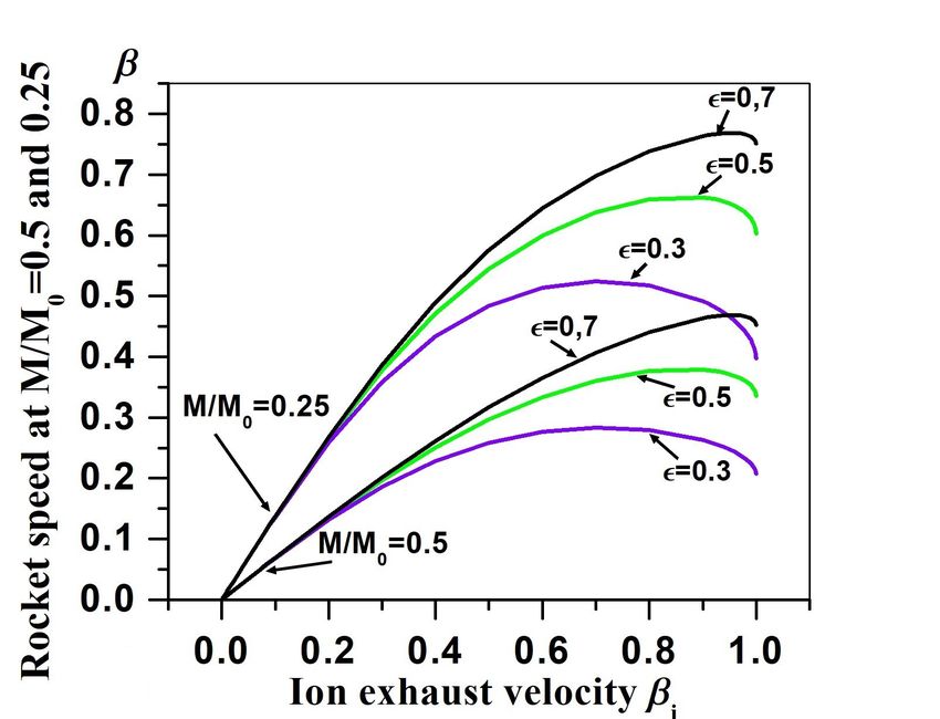
Radiation Conditions in Relativistic Interstellar Flight

F IGURE 4. Five-meter magnetic nozzle to produce thrust by
π-mesons mostly. It consists of the current loops with their
radii increasing to the exhaust end and with their separation
d = 0.33 m between them to produce an almost linear slop of
magnetic inductance B along the z-axis toward the exhaust
end z = 0. Direction of current is indicated by arrows. To
dump partially the tail of non-linear magnetic field near the
exhaust end and to make it as short as possible, three addi-
tional loops carrying the opposite current with respect to all
other loops of the nozzle are added at the exhaust end of the
assembly. The value of current in all the loops I = 2.5×10⁷ A
except the third one from the left, where the current is in-
creased by the factor of 2.5. The position of the pion source
for the calculations of the pion trajectories shown in Figure 5
below is marked by a star. The z-axis is directed along the
magnetic field gradient and the thrust vector. Adapted from
the reference [1, figure 1.14]

tleneck (the nozzle edge with the maximum of mag-
netic field) along the z-axis, i.e. from the right in Fig-        F IGURE 5. Trajectories of the positively charged π-mesons
ures 3 and 4. Both beams must follow the same way and             in a five-meter magnetic nozzle with a linear gradient of mag-
be pretty thin (small diameter) otherwise they will be            netic field calculated for different initial pitch angles (angles
redirected by the strong radial component of the mag-             of emission of π-mesons relative to z-axis). The z-axis is di-
netic field near the entrance into the magnetic nozzle            rected along the magnetic field gradient. Adapted from the
and will never cross to annihilate inside the magnetic            reference [1, figure 1.12]
nozzle [1, p. 41]. Secondly, the calculated π-meson tra-
jectories [1] demonstrate practical impossibility to cre-
ate a nearly parallel exhaust jet of π-mesons and analo-          their original pitch angle sin α < (B/Bm )1/2 , where B
gously of µ-mesons with their velocity vectors closely            is the magnetic inductance at the point of their emission
aligned with the z-axis. It means a reduced thrust and            and Bm is the maximum magnetic inductance at the
the lower rocket acceleration in comparison with an ide-          bottleneck, will not be reflected to the exhaust end but
ally aligned exhaust jet. Another essential drawback of           continue to travel to the rocket body producing firstly
the magnetic mirror is a leak of the charged mesons               some braking thrust and secondly creating a severe ra-
through the bottleneck. Even if we manage to tightly              diation hazard for crew and electronics in addition to γ-
focus the beams and produce an ambiplasma (mixture                radiation from the decaying neutral π-mesons [1, p. 36].
of both beams) in which all the protons and antiprotons           Positioning the point of proton-antiproton annihilation
annihilate inside the magnetic nozzle, the mesons with            closer to the exhaust end of the magnetic nozzle will

DOI: 10.5281/zenodo.3747325                                                                                                     65
Acta Futura 12 (2020) / 61-74                                                                          Semyonov, O.G.

reduce the thrust produced by the π-mesons emitted at         utilized for thrust production. Because of its highest
the initial pitch angles > 90 degrees. Shifting it closer     energy release per unit mass of annihilating matter and
to the bottleneck will enlarge the loss-cone of π-mesons      antimatter (fuel), thus much lower rate of fuel consump-
and µ-mesons escaping through the bottleneck and re-          tion to generate the same power, the antimatter anni-
duce the thrust, too.                                         hilation reactor is preferable for relativistic interstellar
   The only possible protection option against the flux       spacecrafts, provided the problem of antimatter storage
of γ-radiation is a shield of γ-absorbing material. To        on board of a rocket is solved [5]. Its function is to gen-
get an acceleration of a thousand-ton rocket of 1 m/s2 ,      erate the electrical power and supply to one or several
the total annihilation power should be of the order of        ion accelerators of conventional matter to produce the
2×10⁸ MW and the kinetic power of the π-meson ef-             efflux beam of high-energy ions. These fully or partly
flux jet of 5×10⁷ MW [1, p. 56]. The emission rate of         ionized atoms have their kinetic energy E comparable
200 MeV γ-photons will be of the order of 1024 photons        with their mass-energy m0 c2 , where m0 is the mass of
per second which corresponds to the radiation power of        rest, so a significant portion of the reactor power goes
6×10⁷ MW. To reduce the flux of photons to a rela-            predominantly to the kinetic energy of an almost com-
tively safety level, the rocket protecting shield of lead     pletely aligned relativistic jet of ions. To compensate
should be well above one meter in thickness and such a        the positive charge of the ion beams, the emitters of
shield would take a lion’s share of the rocket dry mass.      electrons are to be installed around the exhaust end of
Positioning the propulsion engine sufficiently far from       ion accelerators in analogy with the ion thrusters al-
the control bridge and crew quarters can help to reduce       ready in use at the interplanetary probes. From the
the shield mass due to geometric reduction factor but         rocket equation [1, 2], the achievable speed v0.5 of a
the rocket axial elongation to tens kilometers or more        rocket at the moment, when a half of the rocket launch-
will be hardly acceptable. According to calculations          ing mass M0 is used for propulsion, which includes
performed in [1], the loss-cone of pions through the          propulsion exhaust and matter-antimatter mass loss in
bottleneck of nozzles with the maximum magnetic field         the reactor, is shown in Figure 6 as a function of exhaust
of 100 T is about or wider than 1 sr thus ten or more         ion velocity factor βi = vi /c for several propulsion ef-
percents of π-mesons or µ-mesons will leak through            ficiency coefficients (efficiency of annihilation reactor
the bottleneck to the rocket body creating a huge ra-         with gas turbines for electrical energy production plus
diation hazard in addition to γ-radiation. To screen          the efficiency of ion thrusters) [6]. Also shown are the
the rocket from the flux of charged mesons, a magnetic        graphs of the rocket speed at the moment, when three
shield analogous to the shield against the oncoming nu-       quarters of the rocket launching mass are exhausted.
cleonic flux of interstellar gas (see Section 3) should       The graphs are valid for any launching mass and propul-
be mounted between the nozzle and the rocket body             sion power, however it should be remembered that the
to absorb or deflect the charged mesons. However, it          rocket acceleration and the time of flight to the mo-
cannot eliminate the shield of dense and heavy material       ments, when a half of rocket launching mass (or three
against γ-radiation. Taking into account the problem of       quarters of rocket launching mass) is exhausted, are
injection of proton and antiproton beams into the mag-        functions of the rocket launching mass and propulsion
netic nozzle and a huge practical size of annihilation        power. The graphs of the rocket speed and flight dis-
zone (tens or hundreds of meters) for achievable diam-        tance are given in [1, pp. 65–68] as functions of time
eter of proton/antiproton high-power beams, the direct        of flight measured by the rocket clock for the launching
propulsion by the annihilation products seems to be not       masses of 1000 to 10000 tons and for propulsion power
a promising solution for interstellar relativistic rockets.   of one TW to hundred TW.
                                                                 The advantage of relativistic ion propulsion powered
                                                              by a reactor is that it gives much better freedom and
2.3    Relativistic Ion Propulsion
                                                              flexibility in choosing the energy source and propel-
Alternative antimatter-powered propulsion has been            lant. Also it opens a possibility of independent con-
suggested in [1, 2]. According to the conception, an          trol of kinetic energy and mass flow to the exhaust jet.
antimatter annihilation reactor is used for electrical en-    Any liquidized gas from hydrogen to xenon can be used
ergy production to power a high-energy ion thruster.          for ion propulsion and these elements can be found al-
Basically, any energy-generating reactor (nuclear, ther-      most everywhere in the universe. An increase of ki-
monuclear, or antimatter annihilation reactors) can be        netic energy of ions in the exhaust jet by increasing

66                                                                                            DOI: 10.5281/zenodo.3747325
Radiation Conditions in Relativistic Interstellar Flight

                                                               of γ-radiation or at least a shield is installed between
                                                               the reactor and the rocket’s parts requiring their protec-
                                                               tion against γ-radiation. Possibly, a reactor, in which
                                                               antiprotons irradiate a heavy-nuclei material (e.g. tung-
                                                               sten or uranium), will be advantageous because some
                                                               γ-photons can be absorbed by the nuclei at which an-
                                                               tiprotons annihilate [7] to add energy to the nuclei frag-
                                                               ments (it is supposed that antiproton annihilates with a
                                                               proton or a neutron mostly at the surface of a heavy nu-
                                                               cleus so that the γ-photons entering the nucleus will be
                                                               absorbed inside together with some charged π-mesons
                                                               (pions) resulting in nucleus excitation and possible frag-
                                                               mentation). The charged pions emitted away from the
                                                               nuclei and eventually from the heavy-nuclei material
                                                               will create a radiation hazard on board of a rocket, if
F IGURE 6. Map-velocities β0.5 = v0.5 /c and β0.25 =           they are not absorbed in the reactor’s blanket. A por-
v0.25 /c of a rocket at the moments when the residual mass     tion of γ-rays from the decaying neutral π-mesons not
of the rocket M = 0.5M0 and 0.25M0 as functions of
                                                               absorbed in the annihilating material also add to the ra-
the proper velocity βi of the efflux of protons. The graphs
are shown for the values of propulsion efficiency ǫ =
                                                               diation hazard. Thus, either the reactor blanket should
0.3, 0.5, and 0.7. The graphs are valid for any efflux power   be thick enough to absorb both the mesons and γ quanta
and launching mass. Adapted from the reference [6, figure 2]   or a protecting shield should be installed to protect the
                                                               rocket body. In principle, an annihilation reactor mod-
                                                               ule can be imagined containing a thick chunk made of
their exhaust velocity will results in reduction of the        a heavy-nuclei material with its high melting point (e.g.
propulsion mass flow rate to obtain the same rocket ac-        tungsten), which is irradiated by antiprotons or antihy-
celeration. It allows achieving higher cruising veloc-         drogen molecules (atoms) annihilating at its surface and
ity due to longer thrust with the same propellant re-          depositing the energy of pions and gammas into the ma-
serve and even saving some propellant for braking. The         terial to heat the chunk together with the primary reac-
price we have to pay for the increased exhaust veloc-          tor cooler. If this prime heater is irradiated by antipro-
ity is either a higher energy consumption to get the           tons (antihydrogen) beams from its side opposite to the
same thrust or a lesser rocket acceleration with the same      rocket’s parts sensitive to radiation, it can serve a shield
propulsion power thus longer time for picking-up the           against γ- and meson radiation. Higher kinetic energy
desired speed. Nonetheless, the possibility of achieving       of irradiating antiprotons would be preferable because
a higher rocket velocity at the moment, when a prede-          of the effect of relativistic beaming of the annihilation
termined portion of rocket launching mass is exhausted         products which could increase the portion of mesons
(say, a half of rocket launching mass as in Figure 6),         and gammas entering the nuclei and absorbed by them.
is advantageous because the total time of flight to a re-      Neutrons generated in the process of nuclei fragmen-
mote destination including the stage of rocket cruising        tation can also add to the radiation hazard [7]. Anni-
with the higher constant speed can eventually become           hilation of protons with heavy-nuclei gases and solids
shorter.                                                       gives birth to many other physical effects not properly
   A significant portion of mass-energy of annihilating        studied so far [8]. We must also provide for a means to
atoms and antiatoms in an annihilation reactor can be          replenish the annihilated material on the chunk surface
converted to electricity. The inevitable loss is neutri-       for example covering its working surface by a layer of
nos and antineutrinos escaping freely to space (14.56%         liquid heavy-nuclei material with which antiprotons ac-
of the total mass-energy of annihilating protons and an-       tually annihilate with. A material such as melted metal
tiprotons). Another possible loss (additional 26% of an-       or salt would seep through the pores in the chunk to
nihilation energy) is the γ-photons emitted by neutral         replenish the annihilating liquid layer in analogy with
π-mesons, which can produce a severe radiation haz-            sweating surfaces of the walls of a thermonuclear reac-
ard onboard unless either a thick blanket is mounted           tor suggested many years ago.
around the annihilation reactor for effective absorption

DOI: 10.5281/zenodo.3747325                                                                                             67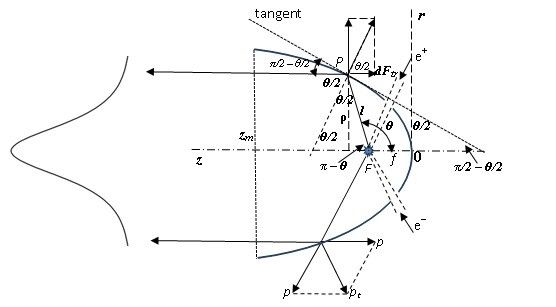
Acta Futura 12 (2020) / 61-74                                                                              Semyonov, O.G.

3      Hard Ionizing Radiation of External
      Origin

3.1    Interstellar Gas
Outer space beyond Earth’s atmosphere is not just an
empty void. Interplanetary space and interstellar space
contain rarefied gas and dust. Interstellar gas is a neces-
sary component of every galaxy: it is constantly replen-
ished by stellar wind (flux of gas and plasma emanated
from the star surface analogous to the solar wind) and
in catastrophic star explosions such as novas and super-
novas. The clouds of interstellar gas give birth to new
generation of stars with their planetary systems, which,
after living through their life cycle, replenish the inter-
stellar gas to give birth to the next generation of stars      F IGURE 7. Flux of interstellar atoms and ions per square
(stellar recycling) [9]. Every galaxy is an evolving sys-      meter per second (dashed) incident on a rocket and the radi-
tem of interdependent stellar and gaseous components.          ation dose rate (rems per second) obtained by an unprotected
Cosmic gas fills our galaxy unevenly: there are rela-          astronaut as functions of rocket map-velocity β = v/c. A
tively low-density regions and denser clouds (our Sun          brake on the graph of the dose rate near β = 0.6 corresponds
                                                               to the velocity at which the penetration depth of the nucleons
was formed in a dense gaseous cloud more than four bil-
                                                               (protons mostly) in the tissue is equal to the average thickness
lions of years ago). Luckily, our Sun is located currently     of a human torso (∼30 cm). Adapted from the reference [6,
in a low-density local cavity about 400 light-years in         figure 3]
size in the Orion spur [10]. Concentration of neutral
and ionized atoms and molecules (mostly hydrogen and
helium) in the local cavity n ∼ 3×10⁵ m-3 . Interstellar       atoms, and molecules in the local cavity P = γnv (in
gas contains about 89% of hydrogen with 10% admix-             the rocket coordinate frame) exceeds 109 per square
ture of helium. Also, it contains about 1% of heavier          centimeter per second (1013 per square meter per sec-
elements like carbon, oxygen, silicon, iron, etc. mostly       ond) for the rocket velocity above 0.3c. The rate of ra-
accreted in dust granules1 [10, 11, 12].                       diation dose absorbed in the tissue of an unprotected
   When a rocket accelerates to a relativistic velocity v,     astronaut will exceed 104 rems per second [1, 13]. Rel-
all gaseous components and dust grains form a frontal          ativistic factor γ in the expression for P is due to the ef-
flow incident on the rocket with the relativistic veloc-       fect of relativistic time contraction. The flux of atomic
ity and this effect is irrelevant to the method of star-       particles and the dose rate for an astronaut without a ra-
ship propulsion, its size, or its mass. The headwind           diation protection are plotted in Figure 7 as functions of
of otherwise innocuous interstellar gas turns into an          rocket velocity factor β = v/c.
ongoing stream of high-energy ions and atoms while                The safe radiation dose is equal to 5 rems according
the dust granules become relativistic micro-projectiles        to the NIST safety regulations. The dose of hundred
bombarding the rocket hull. Kinetic energy of every            rems is considered dangerous due to high probability
particle relative to the rocket is mc2 (γ–1), where m          to develop cancer, and the dose of thousand rems or
is its mass of rest (either a gas atom or a dust grain),       more is almost hundred percents lethal. According to
γ = (1–β 2 )−1/2 , and β = v/c. Kinetic energy of              Figure 7, the lethal dose can be accumulated in the as-
ionized and neutral atoms of hydrogen, which is the            tronaut body in a fraction of a second, if v ≥ 0.3c. To
main component of interstellar gas, exceeds 100 MeV            reduce the dose rate, a robust radiation-absorbing shield
at v > 0.5c and this is actually a high-energy nucleonic       has to be mounted in front of the rocket. Material pro-
radiation analogous to that of high-energy ion beams           tective shield would require tens centimeters of iron or
produced at the high-power accelerators. Despite a deep        several meters of water or ice [1, p. 101], which means
vacuum in interstellar space, the flux of relativistic ions,   many tons of additional mass to the rocket dry mass. A
  1 see also https://en.wikipedia.org/wiki/Local_              magnetic shield alone will not work because of a sig-
Interstellar_Cloud                                             nificant percentage of the neutral component in inter-

68                                                                                                DOI: 10.5281/zenodo.3747325
Radiation Conditions in Relativistic Interstellar Flight
stellar gas. A relatively light-weight shield comprising 3.2 Cosmic Rays and γ-Rays
a magnetic system and a thin electron stripper [1, 13]
can protect the rocket from the relativistic flux of ion- Cosmic rays consist mostly of high-energy protons
ized and neutral components of interstellar gas. The (90%) and α-particles (9%) bombarding an unmoving
shield consists of two parts: a relatively thin solid disk target uniformly from all directions [14]. Their energy
(umbrella) at some distance in front of the rocket and a maximum lies between 300 MeV and 1 GeV. Actu-
solenoid behind it which induces a magnetic field per- ally, radiation hazard caused by cosmic rays is tangible
pendicular to the rocket velocity vector by a winding of both for non-relativistic and relativistic space flights.
superconductive wires [1, p. 112]. The superconducting Strictly speaking, a complete shielding against cosmic
coils can be made of high-temperature superconducting rays would require something analogous to Earth’s at-
ceramics wound around a tank filled with a cryogenic mosphere for example a shell of water of 5 m in thick-
liquid to form either a toroidal solenoid producing the ness around the rocket [15]. This will not be a wel-
azimuthal magnetic field or a flat solenoid to generate a comed solution both for interplanetary and interstellar
field with the strait magnetic lines. High-temperature flights because of a significant increase of rocket dry
superconducting ceramics are known to conduct cur- mass. Even a water shell of 1 m in thickness, satisfy-
rents of more than 1 MA/cm2 and to generate magnetic ing the radiation safety standard, could be excessively
fields up to 30 T [5]. Combination of both geometries heavy. In addition, a layer of dense material will be
can also be implemented to cover all the cross section of needed to absorb the highly penetrating secondary γ-
the rocket body [1, pp. 110–112]. A relatively thin solid and muonic radiation due to cosmic rays collisions with
umbrella in front of the solenoid can be virtually trans- the nuclei of the shield inevitably enlarging the rocket
parent to the oncoming nucleons and atoms. Its purpose mass. If the NASA’s limit of 400 rems per individual
is stripping the neutral atoms from their electrons in or- during his duty (meaning the doubled probability to de-
der to produce a flux of completely charged particles velop cancer) will be accepted for interstellar flights, a
behind. This flux of charged nucleons submerges into thinner material shield therefore its lower mass can be
a tank with liquid hydrogen or helium through the rel- accepted for short-term missions (1 to 5 years). Life-
atively thin superconducting winding around the tank. long interstellar travels will definitely require almost
The charged nucleons gyrate across the magnetic lines complete shielding of the crew quarters.
inside the tank and lose their kinetic energy in collisions In analogy with the phenomenon of aberration of
with the atomic electrons and nuclei of liquid hydrogen. light relative a spacecraft moving with a relativistic
For a rocket speed below 0.8c and a magnetic field in- speed, which is determined by the equation for trans-
ductance of 10 T, the radius of gyration of incoming H formation of incident angles from the map-frame to the
and He nucleons in the tank will be below one meter. comoving coordinate frame [16, 17], an equation for
A magnetic shield of two meters in thickness, which transformation of the angles of incidence of relativis-
is significantly smaller than the full penetration depth tic massive particles moving in space isotropically in
of these nucleons along their trajectories in liquid hy- all directions can be obtained [1, 13]. A frontal shield
drogen (about 10 m), will be sufficient for the rocket installed to protect crew and electronics from the rel-
protection. Possible accumulation of positive charge on ativistic headwind of interstellar gas can also absorb
the tank and on the rocket body will be compensated some portion of cosmic rays because of their increas-
by negatively charged electrons accumulating on the ing beaming with the rocket speed closer to the speed
electron stripper provided the magnetic shield and the of light. However, the beaming effect is not as signifi-
stripper are electrically connected. An additional ad- cant at the achievable rocket speed up to 0.7c (Figure 6)
vantage is that the secondary µ-mesons and γ-radiation to expect a significant reduction in cosmic rays inten-
generated in the tank by gyrating nucleons in their col- sity from the sides. Accepting the average radiation
lisions with the nuclei of a liquid that fills the tank will quality factor Q = 6.5 for cosmic rays (Q = 5 for
not be directed exclusively to the rocket body but dis- protons and Q = 20 for α-particles according to Eu-
tributed over 2π angle reducing their portion directed to ropean Nuclear Society2 ), the estimated annual equiv-
the rocket. The sketch of conceptual relativistic ion- alent radiation dose accumulated in an astronaut body
propulsion rocket containing the most important ele- 2 Radiation
weighing factors, ENS publication,
ments and powered by an annihilation reactor is shown https://www.euronuclear.org/info/encyclopedia/
in Figure 8. r/radiation-weight-factor.htm
DOI: 10.5281/zenodo.3747325 69Acta Futura 12 (2020) / 61-74 Semyonov, O.G.
F IGURE 8. Conceptual relativistic interstellar rocket: 1 – ion thruster (an assembly of ion accelerators producing the beams
of relativistic ions); 2 – propellant tanks; 3 – low-temperature refrigerators; 4 – thermal insulation system; 5 – gas turbines
system to generate electrical power; 6 – annihilation reactor; 7 – control bridge; 8 – crew quarters (if any) or auxiliary
equipment room; 9 – magnetic shields to protect the rocket body and thermal radiators from the headwind of charged nucleons;
10 – electron stripper of oncoming neutral atoms and absorber of oncoming free electrons from interstellar gas; 11 – thermal
radiators for power unit cooling; 12 – antihydrogen tanks. Reproduced from the reference [1, figure 3.7]
1000 MeV. The spectrally integrating flux of γ-rays is
about 10 m-2 s-1 sr-1 photons. Most γ-rays are absorbed
by the Earth’s atmosphere except may be for the most
energetic quanta. For the rocket velocity below 0.7c, the
flux of γ-rays will not differ significantly from the flux
incident on Earth atmosphere and the radiation danger
from galactic γ-rays seems to be not a big concern in
comparison with cosmic rays due to their much lower
intensity unless a starship gets close to a local source of
intense γ-radiation.
3.3 Radiation Impact on Electronic Com-
ponents
F IGURE 9. Annual dose accumulated in an unprotected as- Every high-energy nucleon passing through an elec-
tronaut body from cosmic rays as a function of the rocket ve-
tronic component inevitably produces free electrons,
locity factorβ = v/c.
i.e. it deposits some electric charge in the semicon-
ductor material producing parasitic signals and causing
bits to flip, latch up, or burn out in computer mem-
from unshielded cosmic rays D ∼ 30N rem per year is ory. This deposition of charge can “upset” the mem-
plotted in Figure 9 as a function of the rocket velocity ory circuits, and the upset rate of a particular part of
factor β = v/c, where N is the flux of cosmic rays per electronic equipment caused by cosmic radiation in the
square centimeter per second integrated over the angles vicinity of Earth can vary from 10 per day for commer-
of incidence [13], [1, p. 106]. cial RAMs to 1 every 2800 years for radiation-hardened
Cosmic γ-rays are emitted mostly from the galac- RAMs (radiation-hardened component is a device spe-
tic plane and imaged across the sky as a strip along cially designed to resist nucleonic radiation). Two other
the Milky Way with their maximum intensity in the effects can cause degradation of electronics: a) Total
direction to the center of our galaxy [18]. Some lo- Dose Effect which is the change of electrical properties
cal bright sources such as Crab nebula can add to the of components upon their prolonged exposure to radia-
γ-rays intensity. Intensity of galactic γ-rays expo- tion and b) Displacement Damage which occurs when
nentially decreases in the energy range between 10 to the nucleons slow down and nearly come to rest at the
70 DOI: 10.5281/zenodo.3747325Radiation Conditions in Relativistic Interstellar Flight
end of their penetration depth, where they knock semi- on the materials, electronics, and tissue is not clear.
conductor atoms out of their proper locations in crys- Should we consider them as solid projectiles deposit-
tal lattice creating defects in a crystal structure capa- ing their kinetic energy into materials and producing a
ble of trapping the conduction electrons. The labora- mechanical damage like riffle bullets? Or maybe treat
tory tests of the electronic components irradiated by them better as lumps of densely packaged nuclei and
protons and heavy ions were performed by LaBel et electrons causing ionization and displacement of atoms
al. [19, 20]. SEEs (single event effects) and other ef- and molecules in a target as nucleonic radiation? Relat-
fects were detected virtually in all devices bombarded ing to our experience with common kinetic projectiles
by heavy ions and some showed SEEs under proton ir- such as small-shots, bullets, cannon shells, etc. we are
radiation. The cumulative effects such as degradation inclined to consider relativistic granules as producing
of current transfer ratio, reference voltage degradation, some mechanical damage to materials and tissues. At
functional failure, and displacement damage were com- a relativistic speed however, the kinetic energy of each
monly observed under proton fluence above 1011 cm-2 atom in the grain significantly exceeds the potential en-
protons. The headwind of hydrogen atoms at a rocket ergy of interatomic ties in the lattices of all known ma-
speed above 0.3c in the local low-density cavity exceeds terials thus even the atomic ties of electrons with nu-
3×109 cm-2 s-1 therefore the unshielded electronic com- clei in both the dust grain and the rocket hull can be
ponents will degrade to an inoperable condition in min- disrupted by their collision. Apparently, such a rela-
utes of exposure. Hence, a frontal shield against the nu- tivistic dust grain with its kinetic energy of tens to hun-
cleonic radiation of oncoming relativistic headwind is dreds MeV per atom can be better treated as a micro-
equally necessary for unmanned (robotic) and manned drop of plasma consisting of nuclei and electrons inci-
relativistic spacecrafts. Any relativistic spacecraft, no dent on another dense plasma also consisting of nuclei
matter how small or gigantic it is, must be shielded and electrons. In this case, a portion of atomic elec-
from the oncoming high-energy nucleons. Cosmic rays trons will be stripped away from the dust granule by
seem to be not of great concern for radiation-hardened the frontal material shield (electron stripper), so each
electronics regarding SEEs with their malfunction rate granule becomes an electrically charged micro-drop of
of 10-9 – 10-10 errors/bit per day during relatively short plasma and we can hope on its deflection away of the
missions of years of flight but the effect of cumulative rocket body by the magnetic field of the frontal mag-
degradation of electronic components can be a signifi- netic shield. May be, the nuclei of a grain will scatter
cant damaging factor in the long-range flights of tens of on the nuclei of the shield in agreement with the rela-
years or more without proper protection. tivistic Coulomb scattering effect. There is no theory
of relativistic grain collision with material targets and
it is not clear if we can effectively protect a relativis-
3.4 Interstellar Dust
tic rocket against the oncoming flow of relativistic dust
The concentration of interstellar dust grains with their without a thick and massive bulge of solid material in
sizes from 10-5 to 10-6 m (1 to 10 µm) and their masses front of the rocket. Possibly, a relatively thin shell of
from 10-17 to 10-20 kg is about 10-8 m-3 in the local constantly renewable material such as a layer of freez-
low-density cavity [11, 12]. Dust concentration can be ing ice permanently grown on a mesh of thin tubes with
thousands times higher in the dense clouds of the galac- refrigerating liquid can compensate the loss of material
tic arms. The oncoming dust will bombard the frontal due to sputtering by the dust granules while serving an
parts of the rocket with a rate from 1 to 10 m-2 s-1 , electron stripper for neutral atoms in the oncoming rel-
if β > 0.3. Despite their smallness, the grains can ativistic gas. Obviously, the frontal shield will be the
pierce through the frontal protective shield damaging most vulnerable part of a relativistic spacecraft.
the magnetic coils, walls, and frontal parts of the rocket In addition to gas and dust, interstellar space contains
making micro-holes in the worst scenario or sputtering multi-atomic molecules such as polycyclic aromatic hy-
the shield and rocket hull. Impact of relativistic multi- drocarbons and even fullerens [21] that fill the gap be-
atomic grains on the materials has never been studied tween atomic/molecular gas and dust. Every galaxy
because we do not possess a means for accelerating the including our Milky Way is a dusty place filled with
multi-atomic granules to relativistic velocities. gas and dust which is the necessary component of ev-
To what type of hazard we can relate the oncom- ery galaxy directly participating in the processes of star
ing flux of relativistic dust granules by their influence formation and evolution of galaxies (stellar recycling).
DOI: 10.5281/zenodo.3747325 71Acta Futura 12 (2020) / 61-74 Semyonov, O.G.
Regardless of the means of thrust production and mass map-velocity βjet = (β + βi )/(1 + ββi ) according to
of interstellar module, no relativistic flight can be un- the relativistic addition formula, where β is the rocket
dertaken without a proper protection of crew (if any), map-velocity relativistic factor and βi is the proper ve-
electronics, and construction elements against the on- locity factor of the efflux jet of ions and electrons in
coming relativistic flow of all the components of inter- the rocket coordinate frame. The estimations performed
stellar medium. in [1, pp. 114–115] for 1 TW and 100 TW ion propul-
sion showed inability of the ion efflux beam to com-
pletely ionize the neutral component of interstellar gas
4 Radiation Hazard in Braking Stage and to sweep the ionized interstellar atoms out of the
way at the rocket speed above 0.2c. The only possibil-
We have to mention here a circumstance related to the ity to keep all parts of the rocket together with the ion
radiation hazard on board of a relativistic spacecraft thruster behind the protective shield during the braking
somehow omitted earlier, namely the issue of rocket stage is to make a transformable ion thruster consist-
protection from the oncoming relativistic headwind of ing of several ion accelerator units installed symmetri-
interstellar gas and dust during the braking stage. Obvi- cally around the rocket aft, so that each is able to turn
ously, the frontal shield can perform its protective duty around and to redirect the efflux jet almost ahead of the
from ongoing nucleonic radiation and dust during ac- rocket at a small angle with respect to the rocket ve-
celeration and following cruising with a constant rela- locity vector while avoiding a possible damage of the
tivistic speed, i.e. when the rocket’s nose together with rocket construction elements including the protective
the protective shield is directed strictly forward. In- shield [6]. This way, the thrust engine together with
evitably, the moment will come to start braking in or- the rocket body can remain in the shade of the protec-
der to cancel the rocket speed upon arrival to a desti- tive frontal shield and operate in normal regime. Such a
nation. In order to start braking, the rocket must be ei- transformation widens slightly the angle of propulsion
ther turned around as a whole by 180 degrees or have its jet and may result in some reduction of thrust but it can
parts rearranged to bring the propulsion thruster in front be acceptable accounting for the reduced total mass of
while rotating it around to redirect the efflux jet ahead. the rocket by this moment.
Since the protective shield cannot be placed in front of It should be mentioned that every shielding system
the rocket and obscure the exhaust jet, we have two op- designed for the protection of relativistic rocket or any
tions: either we risk to turn the whole rocket by 180 de- other relativistic spacecraft in the local low-density
grees exposing it to the full fury of the relativistic flux cavity can be insufficient in the high density galactic
of interstellar gas and dust without the protective shade clouds. If we find a way to send the interstellar ships or
of the frontal shield or we transform the rocket keep- modules beyond the local cavity, the navigation charts
ing all vulnerable parts (crew quarters, control rooms, and maps of interstellar clouds will be needed for lay-
radiators, etc.) in the shade of the frontal shield while ing out a safe course through the low-density tunnels in
redirecting the propulsion ion beams mostly forward. the galactic arms.
The first maneuver would leave the propulsion engine
and other parts of the rocket without any protection
against the relativistic headwind of gas and dust un- 5 Conclusion
less the forward efflux jet could be capable of sweep-
ing away the gas atoms (ions) and dust granules in front Among the factors that can potentially limit our pursuit
of the rocket. At a relativistic velocity, no gas dynam- for unrestrained expansion into the universe, ionizing
ics is applicable to estimate the ion jet sweeping ability. radiation originated from the propulsion engine as well
To evaluate the action of the jet ions on interstellar gas as arising from the very fact of rocket movement with
molecules, atoms, and ionized atoms, we must consider a relativistic speed through space filled with rarefied
the processes of atomic ionization and Coulomb scat- gas will be the ones of our highest concerns. Despite
tering [1, pp. 113–116]. Hence the efflux jet of high- the extremely low concentration of gas and plasma in
energy ions emitted from accelerators is supposed to interstellar space, three nucleonic components are haz-
be neutralized by electrons to avoid charge accumula- ardous for crew and electronics on board of a relativistic
tion on the rocket body, the jet is actually a relativistic rocket: neutral and ionized components of interstellar
jet of plasma piercing through interstellar gas with the gas, cosmic rays and galactic gamma-radiation. Inter-
72 DOI: 10.5281/zenodo.3747325Radiation Conditions in Relativistic Interstellar Flight
TABLE 1. Most relevant factors of radiation hazard in the of the rocket. A robust shielding of crew quarters from
relativistic flight. For the products of proton-antiproton an- isotropic cosmic rays will be also needed for the long-
nihilation, the energies of γ-photons and kinetic energies of term interstellar flights. The variety of hazardous ion-
massive particles near the maxima of their energy distribu- izing radiation and potential radiation sources are listed
tions are adapted from the reference [4]. Kinetic energy of in Table 1.
the oncoming nucleons Ek = mc2 (γ–1) is a function of the
In addition to nucleonic radiation, interstellar dust
rocket velocity v through the γ-factor: γ = 1/(1–v 2 /c2 )1/2 .
can cause a mechanical damage of the frontal parts of
Particle a rocket or a relativistic module of any kind. A shield
Radiated
Radiation origin energy against nucleonic radiation of interstellar gas headwind
particles
(MeV) will be the most vulnerable to dust bombardment. At a
Rocket engine: relativistic speed, the dust granules can be rather con-
Photon rocket γ-photons 0.511 sidered as dense lumps of plasma of high-energy nu-
Meson rocket γ-photons ∼200 cleons and electrons, which collide with the nuclei of
π-mesons ∼250 a shield or rocket hull materials knocking atoms from
µ-mesons ∼190 their position in the lattice and producing some sec-
Annihilation γ-photons ∼200 ondary mesonic radiation. Radiation hazard for crew
reactor π-mesons ∼250 and electronics from the oncoming relativistic head-
µ-mesons ∼190 wind and sputtering of the rocket elements by the rel-
Relativistic electrons >0.025 ativistic interstellar dust granules are one of the most
headwind of H ions (protons) >50 serious problems to be solved before attempting a rela-
gas at v > 0.3c He ions (α) >200 tivistic flight to other stars.
Cosmic rays mostly protons 100 – 1000
Galactic γ-rays γ-photons 10 – 1000
References
stellar gas turns into an extremely intense flow of nu- [1] Semyonov, O.G. (2017). Road to the stars: Rel-
cleonic radiation incident on the rocket frontal parts. ativistic rocket. Glasstree Academic Publish-
Even at a moderate relativistic speed, the radiation haz- ing. ISBN 978-1-5342-0322-8. doi:10.20850/
ard originated from the oncoming headwind of nucle- 9781534203228.
ons contained in interstellar gas can be huge (hundreds [2] Semyonov, O.G. (2014). Relativistic rocket:
to thousands rems per second), so that a proper wind- Dream and reality. Acta Astronautica, 99:52–70.
ward shielding becomes a necessity. Unshielded elec- doi:10.1016/j.actaastro.2014.01.027.
tronic components will also degrade in minutes of flight
at a relativistic velocity thus even an unmanned rocket [3] Sänger, E. (1953). Zur theorie der photo-
or a relativistic module of any kind will require protec- nenraketen. Archive of Applied Mechanics,
tion against the nucleonic radiation of oncoming rela- 21(3):213–226. doi:10.1007/BF00535829.
tivistic “headwind”. A thick and heavy material shield
in front is hardly acceptable because of a significant in- [4] Frisbee, R. (2003). How to build an anti-
crease in dry mass. The presence of a neutral compo- matter rocket for interstellar missions-systems
nent in interstellar gas excludes the use of a magnetic level considerations in designing advanced
shield alone. A combination of an electron stripper and propulsion technology vehicles. In 39th
a magnetic shield can be a solution. AIAA/ASME/SAE/ASEE Joint Propulsion
Isotropic cosmic rays can be subjected to frontal rel- Conference and Exhibit, page 4676. doi:
ativistic beaming in the rocket’s coordinate frame, if the 10.2514/6.2003-4676.
rocket moves with a relativistic speed close to the speed [5] Semyonov, O.G. (2017). Diamagnetic antimatter
of light, so that the frontal magnetic shield can absorb or storage. Acta Astronautica, 136:190–203. doi:
deflect cosmic ray nucleons away from the rocket body. 10.1016/j.actaastro.2017.03.012.
However at a moderate speed below 0.7c, the relativis-
tic beaming is not sufficient to significantly reduce the [6] Semyonov, O.G. (2018). Pros and cons of rel-
intensity of cosmic rays from the sides and from the aft ativistic interstellar flight. Acta Astronautica,
DOI: 10.5281/zenodo.3747325 73Acta Futura 12 (2020) / 61-74 Semyonov, O.G.
151:736–742. doi:10.1016/j.actaastro.2018.07. Annual Review of Nuclear and Particle Sci-
012. ence, 33(1):323–382. doi:10.1146/annurev.ns.33.
120183.001543.
[7] Morgan Jr, D.L. (1986). Annihilation of Antipro-
tons in Heavy Nuclei. Technical report, Lawrence
[15] Mallove, E.F. and Matloff, G.L. (1989). The
Livermore National Lab CA.
Starflight Handbook: A Pioneer’s Guide to Inter-
[8] Inokuti, M. (1989). Interactions of antiprotons stellar Travel. John Wiley & Sons. ISBN 978-0-
with atoms and molecules. International Jour- 4716-1912-3.
nal of Radiation Applications and Instrumenta-
tion. Part D. Nuclear Tracks and Radiation Mea- [16] Møller, C. (1972). The theory of relativity. Oxford
surements, 16(2-3):115–123. doi:10.1016/1359- University Press. ISBN 978-1-2451-9403-7.
0189(89)90042-3. [17] McKinley, J.M. (1980). Relativistic transforma-
[9] Kaler, J.B. (1997). Cosmic clouds: birth, death, tion of solid angle. American Journal of Physics,
and recycling in the galaxy. Scientific American 48(8):612–614. doi:10.1119/1.12329.
Library. ISBN 978-0-7167-5075-8.
[18] Hartman, R.C., Kniffen, D.A., Thompson, D.J.
[10] Frisch, P.C. (2000). The galactic environment of et al. (1979). Galactic plane gamma-radiation.
the Sun. Journal of Geophysical Research: Space The Astrophysical Journal, 230:597–606. doi:
Physics, 105(A5):10,279–10,289. doi:10.1029/ 10.1086/157118.
1999JA900238.
[11] Mann, I. and Kimura, H. (2000). Interstel- [19] LaBel, K.A., Marshall, P.W., Barth, J.L. et al.
lar dust properties derived from mass density, (1998). Anatomy of an in-flight anomaly: In-
mass distribution, and flux rates in the helio- vestigation of proton-induced SEE test results for
sphere. Journal of Geophysical Research: Space stacked IBM DRAMs. IEEE Transactions on Nu-
Physics, 105(A5):10,317–10,328. doi:10.1029/ clear Science, 45(6):2898–2903. doi:110.1109/
1999JA900404. 23.736545.
[12] Mann, I. and Kimura, H. (2001). Dust properties [20] LaBel, K.A., Marshall, P.W., Marshall, Cheryl J
in the local interstellar medium. Space Science .and D’Ordine, M. et al. (1997). Proton-induced
Reviews, 97(1):389–392. ISSN 1572-9672. doi: transients in optocouplers: In-flight anomalies,
10.1023/A:1011818226293. ground irradiation test, mitigation and implica-
[13] Semyonov, O.G. (2009). Radiation hazard of rela- tions. IEEE transactions on Nuclear Science,
tivistic interstellar flight. Acta Astronautica, 64(5- 44(6):1885–1892. doi:10.1109/23.658957.
6):644–653. doi:10.1016/j.actaastro.2008.11.003.
[21] Candian, A., Zhen, J., and Tielens, A.G. (2018).
[14] Simpson, J.A. (1983). Elemental and iso- The aromatic universe. Physics today, 71(11):38–
topic composition of the galactic cosmic rays. 43. doi:10.1063/PT.3.4068.
74 DOI: 10.5281/zenodo.3747325You can also read