Raspberry-Pi VGA Fen Logic Ltd.
←
→
Page content transcription
If your browser does not render page correctly, please read the page content below
VGA: DPI/VGA adapter for the Raspberry-Pi                                          Rev 1.0, 8 September 2014

                                   Raspberry-Pi VGA
                                    Fen Logic Ltd.
                                            8 September 2014
                                               G.J. van Loo

Introduction
The GNU GPLv3 license is applicable to this manual and the related databases:
VGA adaptor for the Raspberry-Pi computer.
Copyright © 2014 Fen Logic Ltd.
This document and the related databases are free: you can redistribute it and/or modify it under the
terms of the GNU General Public License as published by the Free Software Foundation, either
version 3 of the License, or any later version. This document and the related databases are distributed
in the hope that it will be useful, but WITHOUT ANY WARRANTY; without even the implied warranty
of MERCHANTABILITY or FITNESS FOR A PARTICULAR PURPOSE. See the GNU General Public
License for more details. You should have received a copy of the GNU General Public License along
with this database. If not, see http://www.gnu.org/licenses/
Thus like with the GNU software, you can replicate this hardware, make derivatives etc. All I ask is
that the original designer (Fen Logic Ltd.) gets mentioned in any direct or indirect copies of this work.
Note that the GPLv3 mentions: "The GNU General Public License is a free, copyleft license for
software and other kinds of works." For contact about this document and/or the databases:
info@fenlogic.com.

The adapter (all SMD resistors are at the other side of the board)

Information
VGA
From the birth of the Raspberry-Pi there have been complaints about the lack of a VGA output. That
has now been remedied. But only for the B+ and at the cost of losing most of your GPIOs.
The BCM2835 has a parallel display interface on the GPIO pins. I did not publish this in the 2835
datasheet as 50% of the DPI pins where not on the GPIO connector, making it impossible to get any
decent video out. The B+ however has all of the necessary DPI signals brought out. Dom has been
working on the software side and the new DPI (read: VGA) driver software has been added to the
latest release.
Resolution & Quality
The VGA output supports the same resolutions as your HDMI one. Thus from 640x480 up to
1920x1024 60fps. At the highest resolution the pixel quality is almost as good as HDMI. If you look
very closely there is a slight pixel crawl. The adapter uses a simple resistor ladder network as digital-
to-analogue converter. Therefore the colour quality depends on how well balanced your resistors are.

                                                    1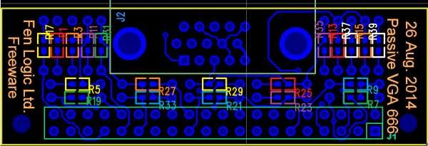
VGA: DPI/VGA adapter for the Raspberry-Pi Rev 1.0, 8 September 2014
The video shown uses an adapter with 1% SMD resistors. There is a slight colour banding and with 6
bits per channel you have a maximum of 262144 colours.
Double screen
In contrast to the composite video, the DPI interface can be run independent of the HDMI. Thus next
to the HDMI screen, the VGA can be used as ‘second monitor’. The software for that is still under
development but I expect that to arrive in the next two week. Beware that running two screens at
maximum resolution will really eat into your SDRAM bandwidth. In fact it has not tried yet, so it
might not be possible.
Where to buy
Nowhere: you can’t buy this anywhere for several reasons which you can find in the manual. But you
can make it yourself, or find yourself an enthusiastic partner and have it made. All the data is in the
public domain at Github: https://github.com/fenlogic/vga666 . Besides the usual: (Manual,
schematics), you will also find the data base for the PCB and the Gerber files. The PCB design
supports both through-hole and SMD parts. The design consists of:
1 PCB
2 connectors
20 resistor.
The cost is not prohibited but having a single PCB made is rather expensive so you might want to
collect a group of interested people and order a batch. I expect in due time that a far-east manufacturer
sees fit to sell them for two dollars. (Batteries not included).
I am in contact with a PCB manufacturer who might put the PCB in their on-line shop for direct
purchase.
Design
The design database consists of:
design_data/schematic/vga.opj
Cadence 16.6 project file
design_data/schematic/vga.dsn
Cadence 16.6 schematics database
design_data/schematic/vga.gif
Screendump of schematic.
design_data/pcb/VGA.pcb
Pads 9.4 PCB database
design_data/pcb/gerbers/*
gerber files, RS-274-X format & readme.
documents/vga_manual.docx
This manual (word 2013)
documents/vga_manual.pdf
This manual (pdf).
Notes
The schematic below shows two columns of resistors. You can mix through-hole or SMD but for each
signal you should mount only one resistor. Thus one of R1 or R2. One of R3 or R4 etc.
The design violates the GPIO specification. You should not draw more than 16mA from a pin. Thus
the minimum resistor is 3.3/0.016 = 206 Ohms. But you will notice that the HSYNC and VSYNC
resistor are less. I tried 200 Ohm but found that it does not work on some monitors. On the prototype I
used 100 Ohm resistors, you might even have to go down to 80 ohms.
The PCB is NOT EMC tested and is likely to radiate a lot. Fortunately the EMC rules do not apply for
home-made electronics. But still you might keep it away from sensitive electronics.
The quality from the colours greatly depends on how accurate your resistors are. Certainly the 499
Ohm should be 1% accurate. You might want to use 500Ohm instead but at 1% that is about the same
as 499Ohm. The 500 Ohm ones are a lot more difficult (and expensive) to obtain.
2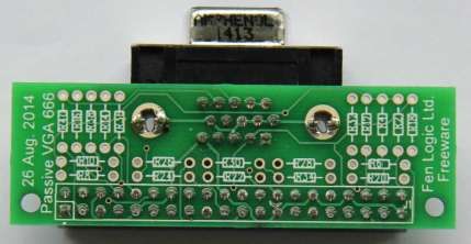
VGA: DPI/VGA adapter for the Raspberry-Pi                                            Rev 1.0, 8 September 2014

Calculations
If you use a different number of GPIO pins the resistor values have to change. These calculations
might help you with that. The impedance of a VGA monitors is 75 Ohms for the colour signals. The
Raspberry-Pi has 3.3 volts coming out of the GPIO pins. The VGA colours signal should be 700mV.
From that we can calculate what the series resistor should be: Rs = 3.3/0.7*75-75 = 278 Ohms. The
series resistors are split into 6 values in the ratio of 1:2:4:8:16:32. These values are placed in parallel.
1/Rs = 1/x + 1/2x + 1/4x + 1/8x + 1/16x + 1/32x A bit of maths gives us that x = 547 Ohms. Thus
officially we need resistor value of 547, 1094, 2189, 4378, 8757, 17514 ohms. But those are difficult
to obtain so I rounded down to 500, 1K, 2K, 4K, 8K and 16K.

The value of the Hsync and Vsycn resistors have been determined empirical.

FAQ
How much CPU power does it use?
Non more than the HDMI output. The video signal is generated by the DPI peripheral, not by bit-
bashing the GPIO pins. However the DPI interface has a much shallower FIFO and thus it is more
likely that the driver does not gets its data in time from the SDRAM (underrun). This shows up as a
horizontal ‘hick-up’ on the screen.
How many GPIO pins does it use?
It uses the GPIO pins 2-21. Thus you only have 6 GPIO pins left: 22..27.
Can I use it on the A or B?
No, it only works on the B+. It is no so much the number of GPIO pins required, the right GPIO pins
are required. The VGA output must have access to at least the MS bits of each colour channel and on
the A and B these are not on the GPIO header for all three colours.
Can I use it with the computer module?
The board will not plug into the computer module as that does not have a GPIO header. But you can
connect the GPIO pins as in the schematic.
Does it work with Minecraft?
Yes, although Minecraft on the Pi writes directly to an image buffer the VGA handling is the same as
the HDMI. (Yes, I tried it :-)
Can I have two independent screens?
Ultimately yes. At the moment the drivers for two independent screens are under development. (In the
demo video we cheated a bit). . Running two screens (or three with the DSI screen?) will use up a lot
of SDRAM bandwidth and not all resolutions on all screens will be possible.
Will it work for XBMC?
Yes, I have been told the change are already in the latest release.
Can I reduce the number of GPIO pins it uses?
Yes. You can drop the LS colours bits of each channel which will free up more GPIO pins but the
picture quality will get worse as you lose more colours. If you use less resistors you also have to adapt
the values. (See section: Calculations).
 Bits/channel         Colours
       6              262144
       5               32768
       4               4096
       3                512
       2                 64
       1                  8

                                                      3
VGA: DPI/VGA adapter for the Raspberry-Pi Rev 1.0, 8 September 2014
Schematic:
4VGA: DPI/VGA adapter for the Raspberry-Pi Rev 1.0, 8 September 2014
Parts:
J1: Female connector 2x20 pins, 0.1” pitch, straight, through hole.
J2: Female D-sub 15 pins, angled, VGA pin pattern. I don’t know in how far all VGA
connectors have the same footprint. I used a VGA connector from Farnell: 2401183.
(AMPHENOL L77HDE15SD1CH4R).
Rx: Resistor 1/8W 1%, values as in schematic.
Installation
Run rpi-update.
Copy the file dt-blob-dpi.bin to boot partition of sdcard, renaming it to dt-blob.bin
(The file is part of the git-hub database download: setup/dt-blob-dpi.bin).
Don’t forget that the dt-blob.bin will disable all GPIOs 2-21 for any other use. Thus if you switch
back to HDMI you might also want to give the dt-blob.bin file a different name.
Add this to config.txt
enable_dpi_lcd=1
display_default_lcd=1
You should now be able to boot with VGA resolution on VGA connector.
You can change resolution with, e.g.
dpi_group=2
dpi_mode=82
(for 1080p60. )
Or:
dpi_group=2
dpi_mode=86
(for 1366x768@60)
You should notice that these settings are identical to the HDMI settings.
The DPI interface (which we use to make the VGA signal) can work in different colour modes. The
default mode is 666 (6 Red, 6 Green, 6 Blue colours). Other supported formats are: 565 (5 Red, 6
Green, 5 Blue colours) and 888 (8 Red, 8 Green, 8 Blue colours). Also there are different ways in
which the 666 and 565 colours bits can be output on the GPIO line. Please see the table below.
Mode RGB GPIO
bits 27 26 25 24 23 22 21 20 19 18 17 16 15 14 13 12 11 10 9 8 7 6 5 4
1 - - - - - - - - - - - - - - - - - - - - - - - - -
2 565 - - - - - - - - 7 6 5 4 3 7 6 5 4 3 2 7 6 5 4 3
3 565 - - - 7 6 5 4 3 - - 7 6 5 4 3 2 - - - 7 6 5 4 3
4 565 - - 7 6 5 4 3 - - - 7 6 5 4 3 2 - - 7 6 5 4 3 -
5 666 - - - - - - 7 6 5 4 3 2 7 6 5 4 3 2 7 6 5 4 3 2
6 666 - - 7 6 5 4 3 2 - - 7 6 5 4 3 2 - - 7 6 5 4 3 2
7 888 7 6 5 4 3 2 1 0 7 6 5 4 3 2 1 0 7 6 5 4 3 2 1 0
You select the mode using: dpi_output_format=X (X in range 1..7)
The VGA adaptor PCB is designed up for mode 5.
5VGA: DPI/VGA adapter for the Raspberry-Pi Rev 1.0, 8 September 2014
Assembly:
First mount all the resistors, then the connectors.
Make sure you enter the connectors from the right side! The connectors are at the same side as the
surface mount resistors.
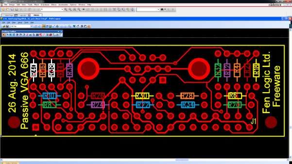
I have made a colour diagram to indicate where the resistors go as the silkscreen was un readable on
my PCBs.:
SMD side (And connector side).
Through-hole side:
Red = 499 Ohm
Orange = 1K Ohm
Yellow = 2K Ohm
Green = 4K Ohm
Blue = 8K Ohm
Purple = 16k Ohm
White = 80..120 Ohm
6You can also read