RBX1 Technical Data - Omicron
←
→
Page content transcription
If your browser does not render page correctly, please read the page content below
RBX1 Technical Data
RBX1 Technical Data

© OMICRON electronics GmbH 2021. All rights reserved.
This technical data sheet was extracted from the following document: ENU 1243 03 04
All rights including translation reserved. Reproduction of any kind, for example, photocopying,
microfilming, optical character recognition and/or storage in electronic data processing systems,
requires the explicit consent of OMICRON. Reprinting, wholly or in part, is not permitted.
The document content represents the technical status at the time of writing and are subject to change
without prior notice.
We have done our best to ensure that the information given in this manual is useful, accurate and
entirely reliable. However, OMICRON does not assume responsibility for any inaccuracies which may
be present. The user is responsible for every application that makes use of an OMICRON product.
OMICRON translates this document from the source language English into a number of other
languages. Any translation of this manual is done for local requirements, and in the event of a dispute
between the English and a non-English version, the English version of this manual shall govern.

2                                                                                            OMICRON

Device overview
1 Device overview
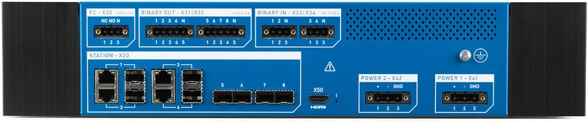
RBX1 front view
Front view
CONNECTION
1 USB connectors Future use – currently deactivated
2 CTRL Network connector
Ethernet connector for control and management interface
LINK (X20)
3 LEDs Status LEDs for Ethernet connectors
Off: no link
On: link established but no activity
Flashing: link and activity
STATUS
4 Device status
READY LED is on when RBX1 is connected to power supply
ERROR
Information is available in the software; severity corresponding to
WARNING
the LED
INFO
5 Mounting holes (×4) For mounting the RBX1 to the rack panel
► For technical data refer to section RBX1 front connectors on page 12.
OMICRON 3
RBX1 Technical Data
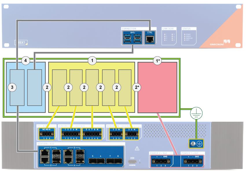
RBX1 back view
Back view
1 FC – X30 Fault contact for RBX1 status indication
Fault contact Form C contact with Normally Closed (NC) and
Normally Open (NO) contact
• X30:1: contact is open when the device is powered on and
functional; otherwise closed
• X30:2: contact closed when the device is powered on and
functional; otherwise open
2 BINARY OUT – X31|X32 Binary output contacts to signal different states of the software
running on the RBX1
Binary outputs
Default setting for StationGuard:
• X31:1 contact is closed when there is at least one
unacknowledged alert (high priority)
• X31:2 contact is closed when there is at least one
unacknowledged warning (low priority)
3 BINARY IN – X33|X34 Binary input contacts to signal different states to the software
running on the RBX1
Binary inputs
4 Grounding screw For connection to protective earth
4 OMICRON
Device overview

Back view
5 POWER 1 – X41                   Connection to power supply
   POWER 2 – X42                  Optional second power supply
6 X50 HDMI                        Future use
7 STATION – X20                   Ethernet connectors for connection to substation
   Network connectors             Link state on RBX1 front (→ LEDs on page 3)
                                  STATION – X20:1 ... 4 are combo ports, so either RJ45 or SFP
                                  can be used. If both are connected, SFP is preferred (→ SFP
                                  modules on page 6).

► For technical data refer to sections Power supply on page 10 and RBX1 back connectors on
  page 13.

OMICRON                                                                                          5
RBX1 Technical Data

2       Accessories

2.1     SFP modules
             CAUTION
             Eye injuries due to laser radiation possible
             If the RBX1 is equipped with an optical SFP module, it is a product of laser class 1
             (IEC 60825), which emits invisible radiation.
             ► Do not look directly into the laser beam or direct it towards other people.

The STATION – X20 connectors on the back side of the RBX1 (→ page 5) support modules with the
following characteristics:

1000 Mbit/s SerDes                                 1000 Mbit/s SerDes or 10/100/1000 Mbit/s SGMII
                                                   with auto-negotiation

        It is possible that modules compliant to the specifications above are incompatible with the
        RBX1. This can be the case if additional configuration data in a module's EEPROM do not
        match the RBX1 SFP ports. To guarantee for compatibility, we recommend using SFP
        modules supplied by OMICRON (→ page 7).

Connecting and disconnecting SFP modules
► Disconnect the RBX1 from mains before swapping SFP modules. A reboot of the RBX1 is required
  for swapped SFP modules to work.
► Refer to the RBX1 user documentation for wiring and safety instructions.

6                                                                                            OMICRON
Accessories
SFP modules available from OMICRON
Module Usable in RBX1 ports
SFP module for 1000Base-SX with LC connector
Multi-mode fiber, 850 nm wavelength
Up to 500 m via 50/125 μm or 300 m via 62.5/125 μm
STATION – X20:1 ... 8
SFP module for 1000Base-LX with LC connector
Single-mode fiber, 1310 nm wavelength
Up to 10 km via 9/125 μm
SFP module for 10/100/1000Base-TX (acc. to IEEE 802.3) with
RJ45 connector
SFP module for 100Base-FX with LC connector*
Multi-mode fiber, 1310 nm wavelength
STATION – X20:5 ... 8
Up to 2 km via 50/125 μm
SFP module for 100Base-LX with LC connector*
Single-mode fiber, 1310 nm wavelength
Up to 10 km via 9/125 μm
* Operating temperature must be above 0 °C (32 °F).
OMICRON 7RBX1 Technical Data
2.2 Adapters
Mains adapter (C14)
A C14 mains adapter (cable length 180 mm) is included in the delivery of the RBX1-40 and RBX1-44
(→ 3.3 Power supply on page 10)
It is designed to supply the RBX1-40 and RBX1-44 in a laboratory environment.
WARNING
Death or severe injury caused by arc fault or electric shock possible
► Only connect the C14 mains adapter to AC supplies.
It is not designed for DC supplies.
► First connect the adapter to the RBX1 and tighten the screws, then connect to
mains AC.
Laboratory adapter package
The RBX1 laboratory adapter package is an optional accessory available from OMICRON.
It contains adapters to 4 mm banana sockets for FC – X30 and all BINARY IN – X33|X34 and
BINARY OUT – X31|X32 interfaces of the RBX1.
WARNING
Death or severe injury caused by arc fault or electric shock possible
► First connect the adapter to the RBX1 and tighten the screws, then connect to the
measurement/test signal.
► Outputs FC – X30 and BINARY OUT – X31|X32, and inputs BINARY IN – X33|
X34 must be protected by a fuse with sufficient breaking capacity (→ Technical
data – Connectors on page 12). This can also be an electronic fuse inside a
laboratory supply.
8 OMICRONRBX1 technical data
3 RBX1 technical data
3.1 Computing performance
Computing performance
Secure cryptoprocessor according to TPM 2.0 (ISO/IEC 11889)
Processors
Quad-core processor with hardware multithreading
16 GB error-correcting code (ECC) memory
Memory
450 GB SSD
3.2 Mechanical data
Mechanical data
Depending on the power supply option:
Weight 6.8 kg ... 7.5 kg
15 lb ... 16.5 lb
482.6 × 88.1 × 303 mm
Dimensions W × H × D 19 × 3.5 × 11.9 in
Required height in rack: 2U
Ingress protection
IP30
IEC 60529
OMICRON 9RBX1 Technical Data
3.3 Power supply
The RBX1 is available with the following power supply options:
• RBX1-20: 1 × power supply option A • RBX1-40: 1 × power supply option B
• RBX1-22: 2 × power supply option A • RBX1-44: 2 × power supply option B
Power supply option A: RBX1-20 and RBX1-22
Input voltage
PHOENIX CONTACT GMSTB 2.5/3-GF-7.62 (socket)
PHOENIX CONTACT GMSTB 2.5/3-STF-7.62 (plug)
Connection
One terminal block for each power supply; maximum conductor
cross-section 2.5 mm2
Nominal voltage 48 VDC ... 60 VDC
Maximum voltage range 44 VDC ... 70 VDC
Nominal input power 65 W
Max. startup inrush currentRBX1 technical data
3.4 Insulation coordination
The RBX1 is a protection class I equipment according to IEC/EN 61140, with insulation designed for
pollution degree 2. The image below outlines what types of insulation apply to different parts of the
device.
Insulation # Power supply Test voltage Impulse test
voltage
RBX1-20/22 1350 VAC 1500 Vpeak
1*
Basic insulation (BI) RBX1-40/44 2200 VAC 4000 Vpeak
1 RBX1-20/22 + RBX1-40/44 2200 VAC 4000 Vpeak
RBX1-20/22 2700 VAC 4000 Vpeak
2*
Reinforced insulation (RI) RBX1-40/44 3250 VAC 6400 Vpeak
2 RBX1-20/22 + RBX1-40/44 3250 VAC 6400 Vpeak
Functional insulation (FI) 3 RBX1-20/22 + RBX1-40/44 2250 VDC N/A
N/A – SELV 4 RBX1-20/22 + RBX1-40/44 N/A N/A
OMICRON 11RBX1 Technical Data
3.5 Connectors
RBX1 front
CONNECTION
USB
Type 4 × USB 3.0 (SuperSpeed, 5 GBit/s)
Connector USB type A
CTRL
Type 10/100/1000Base-TX, according to IEEE 802.3
Connector RJ45
Cable type LAN cable of category 5 (CAT5) or better
Green LED: physical link present
Status indication
Yellow LED: network traffic on interface
12 OMICRONRBX1 technical data
RBX1 back
FC – X30 1
Type Potential-free contacts; software-controlled
Connection PHOENIX CONTACT MSTB 2.5/3-GF-5.08 (socket)
PHOENIX CONTACT MSTB 2.5/3-STF-5.08 (plug)
Maximum conductor cross-section 2.5 mm²
Number of binary outputs 1 form C contact with Normally Closed (NC) and
Normally Open (NO) contact
Number of potential groups 1 (FC – X30)
-X30: 1 2 3
FC
AC loading capacity
Vmax = 250 V, Imax = 8 A, Pmax = 2000 VA
AC breaking capacity
DC loading capacity → Load limit breaking capacity curve for binary output relays with
DC breaking capacity DC voltages on page 15
Inrush current 15 A (max. 4 s at 10 % duty cycle)
Carry capacity 5 A continuous at 60 °C (140 °F)
Electrical lifetime 100,000 switching cycles at 230 VAC/8 A and ohmic load
Operate time2 Max. 10 ms (no bouncing)
Release time 2 Max. 5 ms (no bouncing)
Overvoltage category II, according to IEC 61010-1
III, according to IEC 60255-27
1
Outputs FC – X30 and BINARY OUT – X31|X32 must be protected by a fuse with sufficient breaking capacity: slow-breaking
fuse type, 8 A/250 V. Breaking capacity 50 kA (CAT III) can be decreased by the impedance value of the connection line.
2
Relay timing without software delays
OMICRON 13RBX1 Technical Data
BINARY OUT – X31|X32 1
Type Potential-free contacts; software-controlled
Connection PHOENIX CONTACT MSTB 2.5/5-GF-5.08 (socket)
PHOENIX CONTACT MSTB 2.5/5-STF-5.08 (plug)
One terminal block for each potential group; maximum conductor
cross-section 2.5 mm²
Number of binary outputs 8
Number of potential groups 2 (X31 and X32)
-X31: 1 2 3 4 5 -X32: 1 2 3 4 5
OUT – 1 2 3 4 OUT – 5 6 7 8
AC loading capacity
Vmax = 250 V, Imax = 8 A, Pmax = 2000 VA
AC breaking capacity
DC loading capacity → Load limit breaking capacity curve for binary output relays with
DC breaking capacity DC voltages on page 15
Inrush current 15 A (max. 4 s at 10 % duty cycle)
Carry capacity 5 A continuous at 60 °C (140 °F)
Electrical lifetime 100,000 switching cycles at 230 VAC/8 A and ohmic load
Operate time 2 Max. 10 ms (no bouncing)
Release time 2 Max. 5 ms (no bouncing)
Overvoltage category II, according to IEC 61010-1
III, according to IEC 60255-27
1
Outputs FC – X30 and BINARY OUT – X31|X32 must be protected by a fuse with sufficient breaking capacity: slow-breaking
fuse type, 8 A/250 V. Breaking capacity 50 kA (CAT III) can be decreased by the impedance value of the connection line.
2
Relay timing without software delays
14 OMICRONRBX1 technical data
Load limit breaking capacity curve for binary output relays with DC voltages
DC voltage (V DC) Resistive load
L/R = 50 ms DC current (A DC)
OMICRON 15RBX1 Technical Data
BINARY IN – X33|X34 1
Connection PHOENIX CONTACT MSTB 2.5/3-GF-5.08 (socket)
PHOENIX CONTACT MSTB 2.5/3-STF-5.08 (plug)
One terminal block for each potential group; maximum conductor
cross-section 2.5 mm²
Number of binary inputs 4
Number of potential groups 2 (X33 and X34)
-X33: 1 2 3 -X34: 1 2 3
+ + + +
IN – 1 2 IN – 3 4
– – – –
Max. input voltage 250 V CAT III
Rated input voltage 250 V
Input impedance 148 kΩ
Measurement category CAT III/250 VRMS
according to IEC 61010-2-030
1
Inputs BINARY IN – X33|X34 must be protected by a fuse with sufficient breaking capacity: slow-breaking fuse type, 8 A/
250 V. Breaking capacity 50 kA (CAT III) can be decreased by the impedance value of the connection line.
16 OMICRONRBX1 technical data
STATION – X20
STATION – X20:1 ... 4 1
Type 10/100/1000Base-TX, according to IEEE 802.3
Connector RJ45
Cable type LAN cable of category 5 (CAT5) or better
Green LED: physical link present
Status indication
Yellow LED: traffic on interface
STATION – X20:1 ... 8
Type 1000BASE-X, according to IEEE 802.3
Connector SFP
Status indication LINK (X20), RBX1 front
1
STATION – X20:1 ... 4 are combo ports, so either RJ45 or SFP can be used. If both are connected, SFP is preferred.
X50 HDMI
Type HDMI 1.4, up to 4096 × 2160 at 24 Hz
Connector HDMI type A
OMICRON 17RBX1 Technical Data
3.6 Environmental conditions
The RBX1 is cooled passively. We recommend to leave one rack unit above the RBX1 free for
ventilation.
If the RBX1 is operated in a cabinet, make sure the temperature within the cabinet does not exceed
the limits specified in this document. We recommend ventilating the rack to ensure optimal air flow.
Environmental conditions
Operating –20 °C ... +55 °C
–4 °F ... +131 °F
Temperature
Storage –25 °C ... +70 °C
–13 °F ... +158 °F
Operating 2,000 m
6,561 ft
Maximum altitude
Storage 15,000 m
49,212 ft
Humidity 5 % ... 95 % relative humidity; non-condensing
Mechanical tests 1
Vibration Non-operational 1 g; 5 Hz ... 500 Hz; 40 sweeps per direction
IEC 60068-2-6 During operation 0.5 g; 10 Hz ... 150 Hz; 2 sweeps per direction
10 g/16 ms; 1000 impacts per direction
Shock Non-operational
15 g/11 ms; 3 impacts per direction
IEC 60068-2-27
During operation 5 g/11 ms; 3 impacts per direction
Drop
Non-operational 5 cm, 2 drops per direction
IEC 60068-2-31
1
According to IEC 60255-21-1/2, Class 1
18 OMICRONRBX1 technical data
3.7 Product standards
Generic standards
IEC/EN 61850-3 and IEEE 1613
Electromagnetic compatibility (EMC)
Electromagnetic interference (EMI)
Europe EN 61326-1; EN 60255-26; EN 61000-6-4; EN 55032, Class A
International IEC 61326-1; IEC 60255-26; IEC 61000-6-4; CISPR 32, Class A
USA FCC Subpart B of Part 15 Class A
Electromagnetic susceptibility (EMS)/Immunity level
Europe EN 61326-1; EN 60255-26; EN 61000-6-2; EN 61000-6-5
International IEC 61326-1; IEC 60255-26; IEC 61000-6-2; IEC 61000-6-5
Electrostatic discharge Contact discharge: 6 kV
Air discharge: 8 kV
IEC 61000-4-2
10 V/m, 80 % AM, 1 kHz sinus
80 MHz ... 6 GHz horizontal/vertical
Radiated, radio-frequency,
3 V/m, 80 % AM, 1 kHz sinus
electromagnetic field
1.4 GHz ... 2 GHz
IEC 61000-4-3
1 V/m, 80 % AM, 1 kHz sinus
2 GHz ... 6 GHz
Power frequency magnetic field Permanent: 100 A/m
Short-term: 1 kA/m
IEC 61000-4-8
At 5 kHz and 100 kHz:
Electrical fast transient/burst • FC (X30), BINARY IN/OUT (X31|X32/X33|X34): 4 kVpeak
IEC 61000-4-4 • POWER (X41/X42): 4 kVpeak
• STATION (X20) and CTRL: 2 kVpeak
FC (X30), BINARY IN/OUT (X31|X32/X33|X34):
• Common mode: 4 kV
• Differential mode: 2 kV
Surge POWER (X41/X42):
IEC 61000-4-5 • Common mode: 2 kV
• Differential mode: 1 kV
STATION (X20) and CTRL:
• Common mode (shield–ground): 4 kV
OMICRON 19RBX1 Technical Data
Electromagnetic susceptibility (EMS)/Immunity level
0.15 ... 80 MHz, 10 Vunmod.
27 MHz, 10 Vunmod.
Conducted disturbances 68 MHz, 10 Vunmod.
induced by radio-frequency fields
80 % AM (1 kHz)
IEC 61000-4-6, level 3
FC (X30), BINARY IN/OUT (X31|X32/X33|X34),
POWER (X41/X42), STATION (X20) and CTRL
Voltage dips, short interruptions and
voltage variations on DC input power POWER (X41/X42):
port
Voltage interruption 20 ms
IEC 61000-4-29
Voltage dips, short interruptions and
POWER (X41/X42):
voltage variations
1 cycle (50 Hz)
IEC 61000-4-11
FC (X30), BINARY IN/OUT (X31|X32/X33|X34),
POWER (X41/X42):
Damped oscillatory wave • Common mode: 2.5 kV, 100 kHz, 1 MHz, 10 MHz
IEC 61000-4-16 • Differential mode: 1 kV, 100 kHz, 1 MHz
STATION (X20) and CTRL:
• Common mode: 1 kV, 1 MHz
FC (X30), BINARY IN/OUT (X31|X32/X33|X34):
• Common mode: 300 V (0 Hz, 50 Hz, 60 Hz)
• Differential mode: 150 V (0 Hz, 50 Hz, 60 Hz)
Conducted, common mode
disturbances in the 0 Hz ... 150 kHz POWER (X41/X42):
frequency range • Common mode: 30 V (0 Hz), 300 V (1 s, 0 Hz)
IEC 61000-4-18 STATION (X20) and CTRL:
• Common mode:
30 V (0 Hz, 50 Hz, 60 Hz)
300 V (1 s) (0 Hz, 50 Hz, 60 Hz)
Ripple on DC input power port DC ripple: 15 % nominal voltage, 100 Hz/120 Hz
IEC 61000-4-17
20 OMICRONRBX1 technical data Safety Safety standards Europe EN 61010-2-030; EN 60255-26; EN 61010-1 International IEC 61010-2-030; IEC 60255-26; IEC 61010-1 USA UL; 61010-2-030; UL 61010-1 Canada CAN/CSA-C22.2 No 61010-2-030; CAN/CSA-C22.2 No 61010-1 Certificates OMICRON 21
You can also read