Short Distance Visible Light Communication (SDVLC) - White paper
←
→
Page content transcription
If your browser does not render page correctly, please read the page content below
Ecma/TC47/2011/028
              (Rev. 2 – 15 April 2011)

Short Distance Visible Light
Communication (SDVLC)
White paper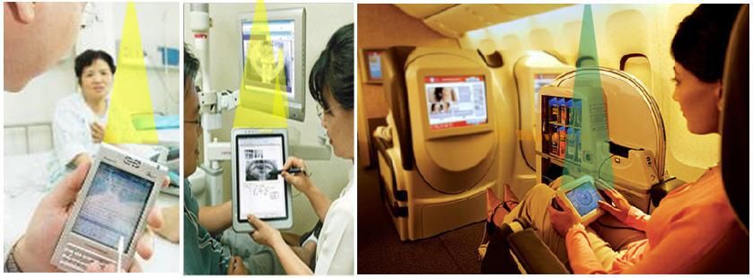
Table of contents

1         Introduction                                                                   1

2         Possible applic at ion areas and use cases                                     2

3         SD- VLC u nique f eat ures                                                     3

4         SD- VLC specif icat ion                                                        4

5         Related T echnologies                                                          5

6         Related standards and ref erences                 Error! Book m ark not def ined.

    6.1     O ther ref er enc es                           Error! Bookmark not defined.

                                                - ii -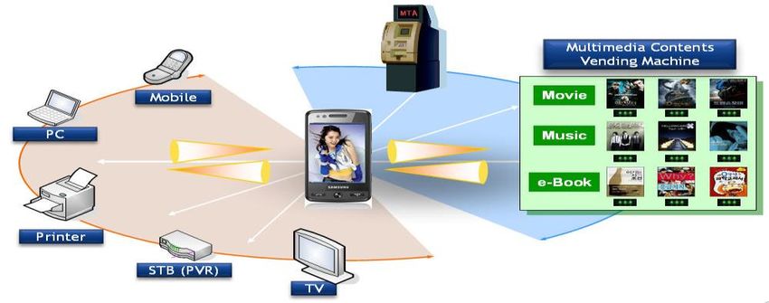
1   Introduction
      With the rapid growth of the Light Emitting Diode (LED) industry, LEDs are increasingly
    being used in many different applications. LEDs have excellent characteristics such as low
    power consumption, small size/high density, high speed response, low cost, long life, and
    excellence in visibility. Current applications for visible light LEDs include color displays, traffic
    lights, streetlights, notice boards, automobiles, cellular phones, light houses, computer
    display/TV backlights, etc. The advent of “white” light LEDs has also allowed the use of LEDs
    in area lighting, soon to replace legacy incandescent, fluorescent, and halogen light sources.
    As interest in using LEDs as lighting sources increases, new innovations for lighting product s
    are being developed.
      Visible light LEDs also can be used for wireless communication.             Because of the fast
    response time of LEDs, LEDs can be intensity modulated (blinked) much faster than the
    human eye can perceive. This blinking can be use to communica te digital data, at bit rates
    greater than 100 Mbps at short distances. An LED can also sense light in a narrow bandwidth
    slightly lower than but overlapping with its illumination frequency, thus the LED can also be
    used as a visible light communication receiver.
      Visible Light Communication        (VLC) proposes to use          visible light   LEDs for data
    communication. In most cases, LEDs with the primary purpose of illumination will take on the
    secondary duty of acting as a digital data communication source; in other cases the LED‟s
    primary purpose will be data communication while the secondary purpose will be to
    communicate visible status to the user.
      With the extension of the application of LEDs from the primary purpose of illumination to the
    secondary purpose of data communication, VLC can be also applied to the NFC area. SDVLC
    technology is a visible variant of NFC using VLC. With SDVLC, “what you see is what you
    send”. Possible applications of SDVLC are mobile to mobile communication and mobile to
    infra-structure communication.

                             Figure 1. What you see is what you send

                                                  1
2 Possible application areas and use cases
SDVLC technology can be broadly applicable for various devices; for example, mobile, PC,
kiosk, payment, multimedia, entertainment, etc. Depending on the application area, SDVLC
has some strong synergy effects because of the unique characteristics of VLC. SDVLC can
easily communicate with other devices in high speed and high security applications. VLC
technology doesn‟t need to consider RF (Radio Frequency) interference issues, because VLC
technology doesn‟t use the RF medium.
Based on the characteristics of the SDVLC application, SDVLC applications can be
classified into two groups; mobile to mobile communication and mobile to infra-structure
communication. For mobile-to-mobile communication systems, non-traditional mobile
equipment and even home appliances can be included in the mobile communication system.
Ever since the appearance of the high-speed access networks, the demand for high speed
communication, which can make it possible to transfer the large volume data , has rapidly
increased. The transmitting speed of the SDVLC can reach over 100Mbps. Many other use
cases can be imagined, such as basic home appliances, e-books, and entertainment using
SDVLC.
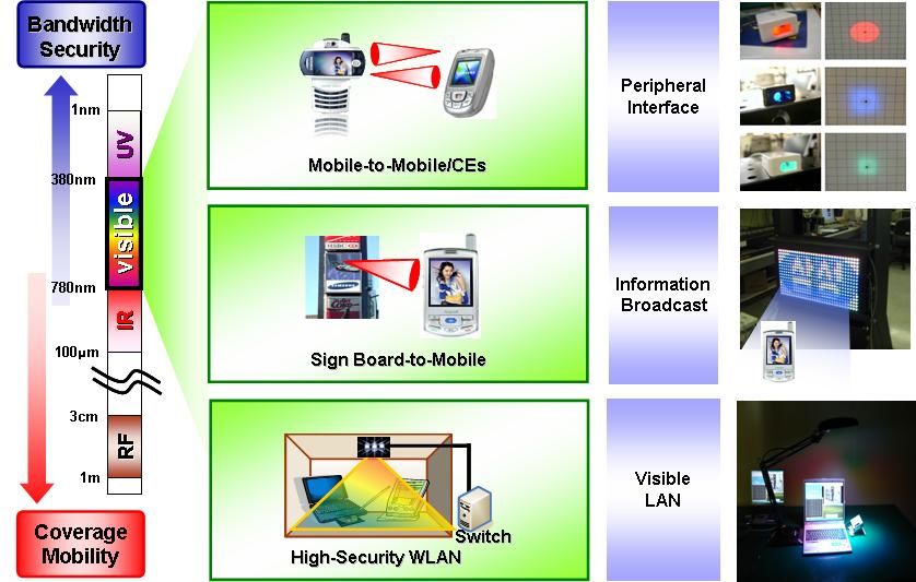
The SDVLC system has many advantageous features and can be used in many places for
the next generation. Figure 2 shows various application of SDVLC.
Figure 2. Various applications using SDVLC
Figure 3. Unique use cases of SDVLC
2Figure 3 shows unique usage cases of SDVLC. SDVLC can be used in RF limited areas
(such as hospital, aircraft, etc). This characteristic is a strong point of SDVLC technology
compared to RF based communication.
3 SDVLC features
User directed communication support in the SDVLC protocol.
Visible Frame (VF) is a key feature of the SDVLC communication protocol. In
order to express communication link status or other feedback, using VF can give
visible communication to the device user.
VF can be sent when there is no data to be sent.
Brightness intensity of light can be controlled by VF frame length and by
changing the proportion of „1‟s and „0‟s in the pattern portion of the VF.
When data are not transmitted, continuous luminescence of LED is
possible by using a VF
Having the communication link be visible is useful.
Normal RF and Infrared based communications needs the user to estimate where
to point the user devices for correct alignment in communication. With the
communication beam visible, pointing the device in the right direction to establish
the link is not a problem.
Laser Diode (LD) or LED is used for the visible transmitter component.
Higher security due to the beam visibility
The user can see if something unauthorized is in the path of the
communication beam, and can see that the beam is sending in the wrong
direction.
Harmless characteristic and non-license for use
Unlike RF communication technology, SDVLC technology is harmless in terms of
radiation damage and electromagnetic compatibility due to the use of the visible
range of the spectrum.
It does not cause malfunction of sensitive aircraft equipment or medical
instruments since SDVLC has no radio wave interference.
The radio wave of wireless communication system is ubiquitous because of cell
phones and wireless access areas. Also, use of the RF spectrum suffers from
frequency allocation problems due to the lack of available radio frequency.
SDVLC doesn‟t have any frequency allocation issues.
As compared to the radio wave wireless communication, SDVLC doesn‟t require
any license.
The protocol for visible light channel link and data throughput.
Visible light communication link is suitable for near field communication based
literally on Line Of Sight (LOS). This communication link has better channel
3-8
condition than Radio Frequency (RF) channel and can obtain minimum 10 Bit
Error Rate (BER) at experimental communication ranges.
Fast and easy connection characteristic
SDVLC can support easy devices connection and transfer data between two
devices over a short range, point-to-point communication link.
Link configuration and speed are transparently negotiated with minimum connect
time.
4 SDVLC specification
SDVLC contains specifications for both the PHY and MAC layers.
For the PHY, SDVLC specifies the characteristics of the transceiver: b oth optical
transmission characteristics and minimum receiver sensitivity. Note that the specification
carefully does not specify that an LED be used; any light emitter that meets the specified
characteristics can be used.
The SDVLC specification modulates the transmitter using On-Off Keying (OOK), which
means that the optical output is switched between a minimum output level and a maximum
output level. Output levels between these two extreme levels are not used; most optical output
devices are not well characterized at output levels between the extremes.
SDVLC specifies two data encoding schemes: 8B10B, which guarantees that the 1 to 0
duty cycle of the data encoding is 50%; and a 2B4B encoding that is less efficient at encoding
the data but has duty cycles of 25%, 50% and 75%. The 2B4B encoding will allow for average
duty cycles of anywhere between 25% and 75% by judicious mixing of the supported base 25%,
50% and 75% duty cycles.
SDVLC has two types of frames: Data Frames and Visible Frames. Data Frame s are
used to communicate data between devices. Visible Frames are used when data does not
need to be communicated; the Visible Frame is not processed by any receiver in view, but is
instead used to modulate the brightness of the light source to give a vi sual indication to the
user. Data Frames and Visible Frames may be used together.
The headers of both types of frames contain a management message field, which can be
used to hold a MAC level management message. The currently defined management
messages are used to manage an association between devices, to set up a burst
communication mode, and to change data encodings.
Since the SDVLC networks are peer-to-peer, any device can initiate the association, using
the association management messages. Similarly, any device in an association can initiate a
disassociation using the disassociation management messages.
Since a device may have several other SDVLC devices in its receiver field of view, the
device needs a way to manage several other devices simultaneou sly. SDVLC has two
mechanisms for handling this case. One mechanism is for a device to prohibit the other
device in an association from transmitting Visible Frames when no data is to be sent (this is
accomplished through a bit in the frame header); by no t sending Visible Frames when no data
is to be sent, the device will not interfere with other devices that are attempting to send data.
The other mechanism sets up periodic or aperiodic data burst schedules that can act as a
somewhat crude time division multiple access (TDMA) method; the pauses in between the
data bursts can be visible frames or transmitter off, which can be commanded by the other
device.
45 Related Technologies
IrDA is a standard defined by the Infrared Data Association (IrDA). It specifies a way to
wirelessly transfer data via infrared radiation. The IrDA specifications include standards for
both the physical devices and the protocols which are used for communication between
devices. The IrDA standards have arisen from the need to connect various mobile devices
together.
The table below compares some of the characteristics of SDVLC and IrDA technology, and
shows some of the advantages of SDVLC.
SDVLC IrDA UFIR
Link Visible range Infrared range Infrared range
Narrow (within 10 degree) Wide (over 30 degree) Wide (over 30 degree)
Angle
Compact Beam Spread Beam Spread Beam
Feature Visible communication link No visibility No visibility
Protocol SDVLC protocol IrDA protocol Ultra Fast IrDA protocol
RZI/4PPM/HHH(1,13)/
Modulation 8B10B and 2B4B RZI/4PPM/HHH(1,13)
8B10B
Data rate 120 Mbps 16 Mbps 120 Mbps
Table 1. Comparison of SDVLC and IrDA technology
Although SDVLC and IrDA have some similiarities in the communication link and physical
structure, SDVLC has a unique communication feature: “what you see is what you send”. By
being able to observe the actual transmission beam, SDVLC can have several advantages
over IrDA.
IrDA uses a wide beam angle to attempt to compensate for misalignment between
transmitter and receiver. Misalignment happens because the user has no way to determine if
the devices are properly aligned or not; in the extreme case the devices are so misaligned that
no communication will result. With SDVLC, on the other hand, the user can see where the
beam is pointed, and thus see when the devices are pointed in the correct direction. T hus
SDVLC can use a narrower beam width.
Visible Frame can also be used as feedback to the user to minimize mismatched alignment
of devices. In case of alignment mismatch, SDVLC lighting can be flickered using Visible
Frame. Thus the user can recognize poor communication link condition by the flickering light.
The narrow beam of SDVLC gives less of an opportunity for eavesdropping; with a narrow
beam, little or none of the beam could leak past the receiving device, and thus there is less
beam leakage for an eavesdropper to use.
In addition, visibility of the beam gives us an intrinsic security element, because the user can
see if an attacker puts an unauthorized device into the light beam.
5Also, with this narrower beam width, SDVLC will minimize adjacent device interference. If an
IrDA source device wants to connect to another device that happens to be close to a third
device, then because of the wide beam in IrDA, the IrDA system design requires interference
avoidance protocols. This means that, in order to assure system QoS, the system design for
IrDA needs to be more complex for interference reduction. SDVLC, with its narrower beam,
will greatly decrease if not eliminate adjacent device interference. Plus, the beam can be
easily blocked from illuminating more than one device at once.
One obvious issue with SDVLC systems is the need to avoid interference from other visible
light sources (such as the Sun) and multi-path interference from reflections. Noise from
ambient light such as sunlight, fluorescent light, incandescent light, etc. is very important
issues for the SDVLC system. The right optical filter and modulation scheme are needed to
reduce interference from ambient light. For our eye‟s safety, even with visible light, power
limits should be considered in SDVLC.
6You can also read