Reliable Automatic Camera-Laser Calibration
←
→
Page content transcription
If your browser does not render page correctly, please read the page content below
Reliable Automatic Camera-Laser Calibration
                                Abdallah Kassir and Thierry Peynot
                           ARC Centre of Excellence for Autonomous Systems
                                   Australian Centre for Field Robotics
                             The University of Sydney, NSW 2006, Australia
                          {a.kassir@acfr.usyd.edu.au, tpeynot@acfr.usyd.edu.au}

                      Abstract                               the paper presents algorithms that automate two exist-
                                                             ing trustful calibration methods which rely on observing
    Camera-laser calibration is necessary for many
                                                             a calibration object and which jointly achieve complete
    robotics and computer vision applications.
                                                             camera-laser calibration: Bouguet’s Camera Calibration
    However, existing calibration toolboxes still re-
                                                             Toolbox [Bouguet, 2010] and Zhang and Pless’s extrin-
    quire laborious effort from the operator in order
                                                             sic camera-laser calibration technique [Zhang and Pless,
    to achieve reliable and accurate results. This
                                                             2004b]. To use these techniques, the operator is required
    paper proposes algorithms that augment two
                                                             to obtain a calibration dataset, which is a set of syn-
    existing trustful calibration methods with an
                                                             chronised pairs of images and laser scans, containing a
    automatic extraction of the calibration object
                                                             chessboard and taken from different poses. The chess-
    from the sensor data. The result is a complete
                                                             board acts as the calibration object and the size of its
    procedure that allows for automatic camera-
                                                             squares needs to be measured. For the camera calibra-
    laser calibration. The first stage of the pro-
                                                             tion, the corners of the chessboard squares need to be ex-
    cedure is automatic camera calibration which
                                                             tracted from the images. In the toolbox, this is attained
    is useful in its own right for many applica-
                                                             by the outer corners being selected manually. The tool-
    tions. The chessboard extraction algorithm it
                                                             box outputs the camera intrinsic parameters as well as
    provides is shown to outperform openly avail-
                                                             the rigid transformation from the camera to the chess-
    able techniques. The second stage completes
                                                             board for each image. The transformation is necessary
    the procedure by providing automatic camera-
                                                             for the camera-laser calibration technique cited above.
    laser calibration. The procedure has been ver-
                                                             The camera-laser calibration then uses the points orig-
    ified by extensive experimental tests with the
                                                             inating from the chessboard which appear in the laser
    proposed algorithms providing a major reduc-
                                                             scans to find the camera-to-laser rigid transformation.
    tion in time required from an operator in com-
                                                             Typically, these points have to be extracted manually.
    parison to manual methods.
                                                             In both cases, the extraction process is the key time
                                                             consuming task for the operator. Aimed at automat-
1   Introduction                                             ing the entire procedure, two algorithms are presented:
Despite being extensively carried out across different       the first automatically extracts the chessboard corners
robotics and computer vision applications, camera-laser      from each image and the second extracts the chessboard
calibration remains a challenging problem. Existing cal-     points from the laser scans. With the aid of these al-
ibration toolboxes still require laborious effort from the   gorithms, the required operator time is reduced to what
operator in order to achieve reliable and accurate re-       is needed for acquiring the calibration dataset and mea-
sults. This paper presents an automatic, robust and          suring the size of the chessboard squares. The procedure
complete procedure for the calibration of a perspective      has been verified by extensive experimental tests. The
camera with a 2D laser range finder. The goal of the         automatic chessboard extraction algorithm is shown to
procedure is to find accurate estimates of the intrinsic     produce improved results over existing methods. The au-
parameters of the camera and the rigid transformation        tomatic camera-laser calibration method demonstrates
between the camera and the laser under the assump-           accuracy while significantly reducing operator time when
tion of known intrinsic parameters of the laser. The         compared to manual methods.
work has been divided into two stages: automatic cam-
era calibration and automatic extrinsic camera-laser cal-     Section 2 details the proposed method for the auto-
ibration. Rather than pursue self-calibration methods,       matic calibration of the camera alone. It first examines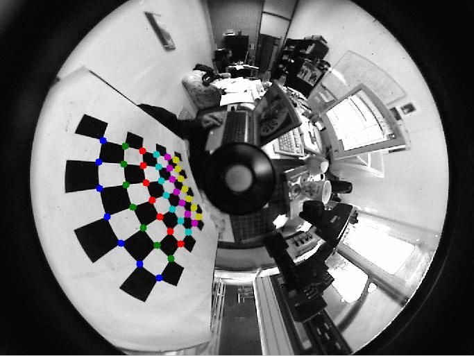
existing automatic camera calibration techniques, then          rely on line fitting or the Hough transform. It is sus-
explains the proposed chessboard extraction algorithm.          pected that such algorithms will be greatly affected by
Section 3 describes the automatic camera-laser trans-           nonlinear distortion. The algorithm in [Ha, 2009] is
formation estimation method. A concise survey is pre-           an improved version of the original algorithm described
sented followed by the suggested chessboard extraction          in [Ha, 2007]. The latter introduced an interesting chess-
from laser algorithm. Finally, Section 4 draws conclu-          board corner filter. Unfortunately, neither this algorithm
sions and directions for future work.                           nor any of the previously mentioned discuss the effect of
                                                                image conditions, such as scale and illumination for ex-
2     Automatic Camera Calibration                              ample, on tools used such as the Harris corner finder
                                                                or the Hough transform. On the other hand, the algo-
2.1    Existing Methods                                         rithm introduced below introduces feedback which deals
Camera self-calibration, which is a calibration process         with the problem of scale. It also suggests a means to
that does not require an explicit calibration object,           automatically select a region for the chessboard corner
has been studied extensively by researchers [Faugeras           filter.
et al., 1992; Hartley, 1994; Luong and Faugeras, 1997;
Pollefeys, 1999]. However, a fully automatic version            2.2   The Algorithm
of self-calibration is yet to become reliable due to the        As with any image feature extraction algorithm, the per-
point correspondence problem and restrictive assump-            formance of an automatic chessboard extraction algo-
tions [Bougnoux, 1998; Remondino and Fraser, 2006].             rithm needs to be examined under different conditions.
Moreover, self-calibration does not provide the extrinsic       If the issues associated with the change in conditions are
parameters required for the extrinsic camera-laser cali-        carefully addressed and the algorithm is tested with a
bration.                                                        large number of images from different datasets, a reliable
   Meanwhile, numerous algorithms for automatically ex-         algorithm can be obtained. The algorithm introduced
tracting the chessboard grid from an image exist with           below is focused on addressing the following issues:
varying degrees of automation and reliability. OpenCV             • Illumination invariance
offers an automatic extraction function using Vezhn-
evets’s algorithm [Vezhnevets, 2010]. Rufli [Rufli et             • Scale invariance
al., 2008] suggests an improved version of the algo-              • Clutter immunity
rithm which is provided in the OCamCalib Matlab Tool-
box [Scaramuzza, 2009]. The two algorithms rely on de-            • Minimising the number of user tuned parameters
tecting quadrangles obtained through the erosion of the         By addressing these issues, the algorithm’s capability su-
binarised image. Since they rely on the separation of           persedes that of any of the openly available existing al-
the chessboard quadrangles, they are sensitive to image         gorithms as summarised in Table 1. Our algorithm man-
blur. Moreover, they do not automatically deal with             ages to encompass necessary features missed by existing
cases where the full grid was not found.                        algorithms. This is achieved mainly through the careful
   Another group of algorithms relies on detecting Har-         choice of a combination of detection tools in addition to
ris corners or feature points which are then arranged           introducing feedback.
into a grid. Some of these algorithms apply a classifier           The steps of the algorithm are listed below. The first
to filter out non-chessboard corners, such as [Ha, 2009;        step is adaptive contrast enhancement which is detailed
Zhou and Fang, 2010; Wang et al., 2010] while others            in Section 2.3. This is followed by a Harris corner finder
do not, such as [Douskos, 2008]. Without the use of a           using three different window sizes. For each size, the
classifier or filter, performance is greatly degraded by        Harris corners are passed through a chessboard corner
clutter. It has been noticed that existing algorithms are       filter similar to that suggested in [Ha, 2007]. Out of
complementary in some sense. For instance, the chess-           the sets of corners obtained for each window size, the
board corner filter in [Ha, 2007] could aid the algorithm       one with largest number of corners remaining after the
suggested in [Douskos, 2008]. This complementariness            filter is chosen for the next step. This process is ex-
was exploited in this work to produce a robust extrac-          plained in Section 2.4. This set of candidate corners is
tion algorithm.                                                 then arranged into a grid. The grid arrangement step is
   DLR CalDe [Strobl et al., 2009] is another piece of soft-    comparable to that used by [Douskos, 2008]. The grid is
ware which offers automatic chessboard corner detection;        then filtered for outliers and missing corners are linearly
it requires a chessboard with three solid circles at its cen-   interpolated. Grid extraction is described in Section 2.6.
tre. In some cases, it also requires erroneous points to        The grid is finally fed into Bouguet’s calibration optimi-
manually be removed. Algorithms in [Wang et al., 2010;          sation routine. In the following sections, the steps of the
Zhou and Fang, 2010; de la Escalera and Armingol, 2010]         algorithm will be described with further detail, highlight-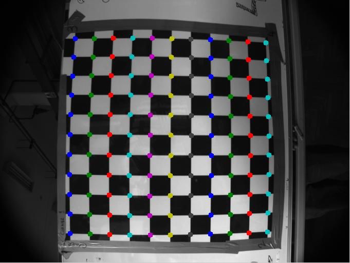
Table 1: Comparison of features offered with existing toolboxes
                                 Scale invari-    Lightness      Clutter      Distortion     Limited use
                                 ance             invariance     immunity     invariance     of thresholds
             OCamCalib           3                3              8            3              3
             FAUCCAL             8                3              8            3              3
             OpenCV              3                8              8            3              3
             Ha’s Method         8                3              3            8              8
             Our Algorithm       3                3              3            3              3

ing the approach taken to solve each of the issues listed      2.4   Harris Transform Window Size
earlier.
                                                               The window size chosen for the Harris transform affects
Automatic Chessboard Extraction Algorithm                      its performance. The window has to be large enough in
                                                               order to detect a corner in the region as opposed to an
 1. Apply adaptive contrast enhancement.                       edge. However, if the window size becomes comparable
 2. Choose three different window sizes for the Harris         to the size of the chessboard squares in the image, adja-
    corner finder.                                             cent corners can get fused together. Therefore, choosing
                                                               the right window size is essential for the successful ex-
 3. For each window size, apply the corner finder then         traction of the chessboard corners. In order for the algo-
    run the detected corners through the chessboard            rithm to be able to automatically select the appropriate
    corner filter.                                             window size, it needs a metric or a reward. Once that
                                                               is available, it can simply choose the window size with
 4. Choose the largest set of corners for the next step.
                                                               the highest reward. The proposed reward is the number
 5. Arrange the corners into a grid.                           of corners that pass the chessboard corner filter. This
                                                               introduces feedback into the algorithm. To the best of
 6. Remove grid outliers and interpolate missing cor-
                                                               our knowledge, none of the existing algorithms employ
    ners.
                                                               this feedback to improve the performance of the Harris
 7. Run Bouguet’s calibration routine.                         corner detector. This feature of the algorithm introduces
                                                               reliable scale invariance.

2.3   Adaptive Contrast Enhancement                            2.5   Chessboard Corner Filter

An image taken under poor lighting conditions lacks high       Constructing the chessboard grid crudely from the Har-
contrast within the chessboard and hence will decline          ris corners can result in failure on cluttered images.
the quality of the Harris transform, which relies on in-       The chessboard corner filter is the key to clutter immu-
tensity differences. Nevertheless, the intensity difference    nity. It provides a distinctive advantage over methods
between the chessboard’s black and white squares can           that do not employ such a filter, e.g. [Vezhnevets, 2010;
be exploited through adaptive contrast enhancement.            Rufli et al., 2008; Douskos, 2008; Strobl et al., 2009].
Global contrast enhancement investigates the properties        The design of this filter is based on the method described
of an image as a whole and then applies the same inten-        by Ha [Ha, 2007]. The filter classifies corners using two
sity transformation for all pixels, while adaptive contrast    criteria:
enhancement looks at the local properties of the image.         1. A chessboard corner lies at the intersection of two
The version of adaptive contrast enhancement used here             edges.
adjusts the intensity of each pixel based on the mean
                                                                2. The area around the corner consists of alternating
and standard deviation of the intensities inside a win-
                                                                   white and black or high and low intensity regions
dow around that pixel. Taking into account different
                                                                   corresponding to the chessboard squares.
possible image sizes, the window size is chosen propor-
tional to the image size. Adaptive contrast enhancement        The chessboard corner filter serves to classify corners
achieves the required illumination invariance. After the       either as part of a chessboard or as a corner in the back-
Harris transform of an image is obtained, a thresholding       ground. The filter checks the properties of the region
mechanism is utilized to obtain blobs around the cor-          around the corner pixel. The filter in [Ha, 2007] re-
ners. The centroids of the blobs are extracted as pixels       lies on user-selected parameters to define the test re-
representing the Harris corners.                               gion. To achieve the goal of minimising the number of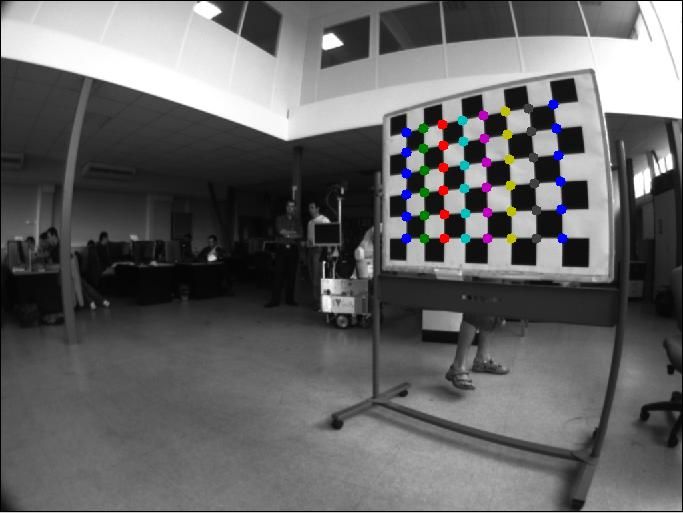
user-defined parameters, our algorithm automatically se-      2. Place this corner in the middle of a large empty
lects the region by expanding a square window until it           array. This corner becomes the current corner.
approaches neighbouring Harris corners. The main as-          3. From the current corner, obtain the nearest 8 cor-
sumption is that most chessboard corners were success-           ners, in Euclidean distance sense, from the list of
fully detected by the Harris corner finder and that no           candidate corners.
Harris corners other than those corners exist inside the
chessboard area. Based on this assumption, the region         4. Sweep the region in the edge image around the cur-
chosen for the filter is the largest square region centred       rent corner to obtain the direction of the four peaks.
at the corner not including any other corners. Fig. 1         5. For each peak, choose the corner, out of the nearest
shows the selected region marked in yellow for a certain         8, that occurs along the direction corresponding to
corner.                                                          the peak. These should be the adjacent corners.
                                                              6. Arrange the adjacent corners according to their an-
                                                                 gle, to be placed in the array around the current
                                                                 corner. If the current corner is the first corner in
                                                                 the array, then choose a random reference direction.
                                                                 Otherwise, look for corners already existing on the
                                                                 array and match to make the direction consistent.
                                                              7. If a match is found or if the current corner is the
                                                                 first corner in the array, place the adjacent corners
                                                                 in the array, mark the current corner as expanded
                                                                 and mark the adjacent corners as unexpanded; oth-
                                                                 erwise, if no match is found, remove the current
                                                                 corner from the array.
                                                              8. If there still are unexpanded corners, move on to the
Figure 1: Automatic selection of test region. A square           next unexpanded corner which becomes the current
region (yellow box) centred at a Harris corner is ex-            corner and go to step 3. Else, end.
panded until it hits other Harris corners (red circles).
                                                                Corners not belonging to the chessboard might pass
                                                             the filter and erroneously tag to the grid during grid
2.6   Grid Extraction                                        arrangement. Therefore, starting from the border lines,
Grid extraction is a critical step in the algorithm. The     lines are removed if the number of corners existing is less
input to this step is the candidate corners which passed     than half the total length of that line. This is applied
the filter. The output of this step is an array of cor-      continuously until no more lines are removed. Once the
ners whose rows and columns correspond to the rows           grid is filtered, the remaining lines are checked for gaps.
and columns of the chessboard grid. The grid extraction      When a gap is located, the position of the correspond-
algorithm used here is adapted from [Douskos, 2008]. A       ing point is interpolated. A line is fit, in a least squares
feature characteristic of a chessboard pattern is that ev-   sense, to the column and row to which it belongs. The
ery non-diagonal pair of adjacent corners is connected to-   point is then estimated to be at the intersection of the
gether by an edge that has a constant gradient direction.    two lines. Finally, the sub-pixel corner finder provided
In other words, along the connecting edge, one side is       by Bouguet is used to find the sub-pixel location of all
white and the other side is black. The gradient direction    the corners in the extracted grid. The grid is then ready
can easily be obtained from the Sobel edge transform.        to be fed into the calibration routine of Bouguet’s tool-
Given any chessboard corner, the other four adjacent         box which runs an optimisation to retrieve the camera
corners can be found using the criteria mentioned. The       calibration parameters.
starting point is chosen as the candidate corner which is       Results and comparison of the extraction algorithm in
closest to the mean of the candidate corners’ (u, v) co-     addition to a comparison of calibration results are shown
ordinates. The steps of the grid arrangement algorithm       in Section 2.7.
are listed below. Grid arrangement corresponds to step
5 of the automatic chessboard extraction algorithm.          2.7    Experimental Results
                                                             The automatic chessboard extraction algorithm has been
Grid Arrangement Algorithm                                   tested on more than 200 images acquired by different
 1. Get the corner closest to the mean of the candidate      cameras under different scale, lighting, clutter and dis-
    corners’ (u, v) coordinates.                             tortion conditions. Fig. 2 illustrates scale invariance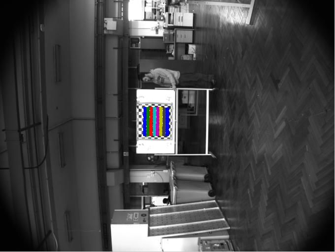
where the ratio of the size of squares between the im- step of the procedure.
ages is approximately 6:1. The image on the right also
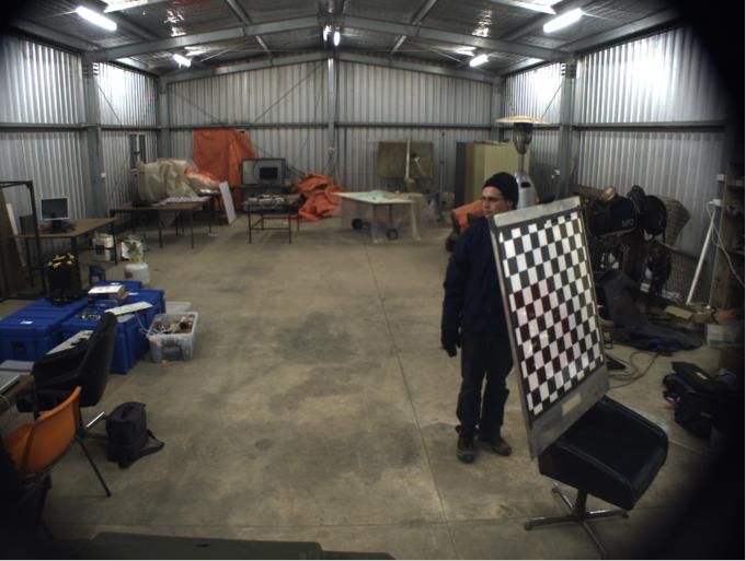
shows the immunity against clutter. Fig. 3 illustrates 3 Automatic Camera-Laser Calibration
the algorithm’s performance under distortion. 3.1 Existing Methods
For the purpose of comparison, we have chosen 99 im-
Most of the work in the area of automating camera-
ages from 6 different datasets. The test datasets include
laser calibration focuses on self-calibration. Zhang and
all the sample images provided by the toolboxes listed in
Pless [Zhang and Pless, 2004a] presented a method for
Table 2 in addition to three of our own. The images were
the self-calibration of a camera with a laser range finder.
sorted into categories according to their scale, illumina-
The method uses motion information from the sensors
tion, clutter and distortion properties. Table 2 displays
and epipolar constraints to optimise the calibration, all
the comparison with the other toolboxes. The values in
of which are heavily reliant on establishing point corre-
the table are the percentage of the images from which the
spondences. Moreover, the results in the paper are not
toolboxes extracted a grid which is useful for calibration.
comprehensive enough to establish confidence. Scara-
The values in the table show a significant advantage for
muzza [Scaramuzza et al., 2007] presents another self-
our algorithm in regards to illumination conditions and
calibration method using a 3D laser range finder where
scale. This can be attributed to the feedback in the al-
the operator is required to manually select corresponding
gorithm. As mentioned in Section 2.1, existing methods
features. Self-calibration methods still require point cor-
fail to address the issue of scale. This is confirmed in the
respondence establishment from the sensor data and lack
results as the table shows extremely low scores for im-
the required accuracy for most applications in robotics.
ages with poor scale. Also evident from the table is the
Therefore, we have chosen to automate the manual ex-
improvement in performance under clutter compared to
trinsic camera-laser calibration method by Zhang and
FAUCCAL due to the use of a chessboard corner filter.
Pless [Zhang and Pless, 2004b].
Another interesting observation is the excellent perfor-
mance of our algorithm under distortion. 3.2 The Algorithm
Table 3 shows a comparison of the calibration re- Through a similar approach to Section 2, the algorithm
sults obtained via both manual and automatic extraction here is designed for the automatic extraction of the chess-
using Bouguet’s sample dataset and another from the board from the 2D laser dataset. A single 2D laser scan
Marulan datasets [Peynot et al., 2010]. The results show gives very little information about the location of the
no degradation in the quality of calibration for Bouguet’s chessboard line. Much more information can be gained
dataset and a minute effect on the results for the Maru- by the integration of information from the entire dataset.
lan dataset. In either case, the RMS pixel reprojection Therefore, in the algorithm described in this section,
error was below 0.2 pixel. chessboard extraction is achieved by using the entire
The automatic extraction of the chessboard grid has a dataset to estimate the length of the chessboard in the
reasonable runtime of 9 seconds per 1.3 megapixel image laser scans and through the iterative refinement of the
on a standard 2.1GHz dual-core PC. Manual extraction transformation estimate (Section 3.4).
achieved by an operator has been estimated to take an The flow of the algorithm is shown in Fig. 4. The algo-
average of 20 seconds per image. Consequently, by us- rithm begins with straight line extraction, explained in
ing our automatic extraction, at least 10 minutes of de- Section 3.3. Once the straight lines are extracted, they
manding operator time are substituted by 4.5 minutes of need to be classified into chessboard or background lines.
computer time for a 30-image dataset. From the classified lines, an estimate of the camera-laser
By augmenting the automatic chessboard detection al- rigid transformation is obtained. This transformation is
gorithm to Bouguet’s toolbox, automatic camera calibra- then further used to aid in the classification. Iteratively,
tion is achieved. Besides the acquisition of the calibra- the transformation is refined until the same lines are re-
tion images, the only required effort from the operator selected indicating convergence of the classification. At
is to provide the toolbox with the size of the squares. this point, the final calculation of the camera-laser trans-
Contrary to some existing methods, this automatic ex- formation is performed.
traction does not require the number of squares along
each dimension of the chessboard. However, if the size 3.3 Straight Line Extraction
of the chessboard squares is not the same along each Many algorithms exist for extracting straight lines from
dimension, the chessboard direction should be consis- 2D laser scans. [Nguyen et al., 2007] contains an exten-
tent throughout the dataset. Automatic camera calibra- sive survey of existing line extraction algorithms. Unfor-
tion can be useful in its own right for many applications. tunately, experimentation with these existing algorithms
Nevertheless, it is a necessary step towards automating failed to produce satisfactory results for the purpose of
camera-laser calibration. Section 3 discusses the second our algorithm. The standard Hough transform suffers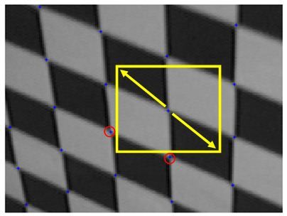
(a)                                             (b)

Figure 2: Illustration of the algorithm’s scale invariance. The size of the chessboard squares in pixels has a ratio of
6:1 between the two images. The coloured dots represent the extracted chessboard corners.

                (a) (Original image from LAAS-CRNS)           (b) (Original image from [Scaramuzza, 2009])

Figure 3: Illustration of the algorithm’s performance under distortion. The coloured dots represent the extracted
chessboard corners.

Table 2: The performance of algorithms under different image conditions. A total of 99 images from 6 different
datasets were used. The images were categorised as follows: poor illumination (45 images), poor scale (chessboard
covers less than 1/5 of the image)(25), cluttered (70), high distortion (36). The values in the table are the percentage
of successful grid extractions from each category.
                     Images    with      Images     with     Images      with    Images with high dis-       Total
                     poor illumina-      poor scale          clutter             tortion
                     tion
  OCamCalib          4.44%               8%                  67.14%              100%                        56.56%
  FAUCCAL            44%                 0%                  37.14%              72%                         55.55%
  OpenCV             4.44%               0%                  62.85%              97.22%                      55%
  Our Algorithm      97.77%              96%                 98.5%               100%                        98.98%
Table 3: Comparison between the calibration results from the manual corner extraction and our automatic chessboard
corner extraction (Error: 3 times the standard deviation).
Bouguet’s Dataset Marulan Dataset
Automatic Corner Manual Corner Automatic Corner Manual Corner
Extraction Extraction Extraction Extraction
Focal length ± Error [657.37, 657.74] ± [657.39, 657.76] ± [1024.74, 1022.31] ± [1023.91, 1020.98]
(in pixels) [0.347, 0.371] [0.346, 0.371] [2.679, 2.625] ± [3.779, 3.7]
Principal point ± [302.98, 242.59] ± [302.98, 242.61] ± [659.46, 475.13] ± [665.17, 476.52] ±
Error (in pixels) [0.706, 0.646] [0.705, 0.645] [3.839, 4.001] [5.756, 6.112]
RMS Pixel Error (in [0.126, 0.126] [0.126, 0.126] [0.154,0.146] [0.141,0.118]
pixels)
from its dependence on the density of points which varies
with the variation of the line angle in a 2D laser scan.
Iterative or successive algorithms are susceptible to com-
promising longer lines for shorter ones. Since length is a
classification metric used in subsequent steps, a different
method which ensures the longest lines are extracted had
to be introduced. To simplify the problem, we make the
Get laser scan dataset following assumptions. Occlusions or gaps are not con-
sidered and a straight line for a set of points is simply
Extract straight lines from the line connecting the end points. These assumptions
scans are reasonable for the purpose of calibration since no ob-
jects are expected to be in front of the calibration board.
Classify lines into The selected straightness criterion for the set of points is
board/background the maximum perpendicular distance from the points to
the line. The key idea of the algorithm is to recursively
test every combination of two points in the scan with
Compute a transformation the straight line criterion and then recursively take out
No from the board lines the longest line. The search has a computational com-
plexity of O(n2 ) for each scan with n being the number
of laser points in the scan. However, the runtime is re-
duced by introducing a heuristic. Before the algorithm
begins searching for lines, the scan is dissected at range
Has the transformation jumps larger than a certain threshold. The heuristic also
converged? enforces the no-gap assumption.
3.4 Classification
Other lines in the laser scans, which we call background
Yes lines, might come from walls, tables and other elements
Run final calibration in a structured environment. Thus, to distinguish those
optimisation corresponding to the chessboard, the extracted lines are
subject to a classification process. Three metrics are
Figure 4: Algorithm for the automatic chessboard ex- used for the classification process:
traction from laser scans 1. The frequency of occurrence.
2. The difference in length with the estimated length
of the board.
3. The distance from the estimated position using the
transformation estimate (once available).
Since the calibration process requires the calibration
board to be moved to different poses throughout the cal-ibration dataset, positions in the laser scan which occur throughout the data acquisition. Dataset2 was sourced
quite frequently throughout the dataset are most likely from the Marulan datasets [Peynot et al., 2010]. It in-
to correspond to the background or irrelevant objects cludes 74 scan-image pairs, out of which 64 contained
in the foreground. Therefore, the frequency of occur- a board line. The setup was stationary throughout the
rence is the first metric used. It should be noted that dataset. Dataset3 includes 71 scan-image pairs, out of
the classification process is an iterative process in which which 50 contained a board line, yet the setup was moved
the output of the classification step is used to compute a few times (about 3 times) throughout the data ac-
a transformation estimate which is then used to refine quisition. Extraction results for the three datasets are
the classification and henceforth. Unless provided by summarised in Table 4 in terms of precision and recall.
the user, the length of the board and an estimate of the Note that the thresholds of the algorithm were chosen to
camera-laser rigid transformation do not exist a priori. sacrifice recall for precision. The 100% precision is desir-
Therefore, for the initial iteration, the algorithm marks able since including outlier data points affects the accu-
the line with the lowest frequency value in each scan. Its racy of the calibration results much more than removing
value needs to be below a certain threshold to be consid- some valid calibration points, especially if the dataset
ered as it might be the case that all the lines in a scan is large enough. Table 5 compares camera-to-laser rigid
have a low value, if the board does not exist in the scan transformation estimation obtained via both manual and
for example. Using these marked lines, the length of automatic extraction for the last two datasets. The pa-
the board is estimated and then used to remove outliers. rameter error estimates were obtained using the method
In this way, lines which differ by more than a certain described in [Peynot and Kassir, 2010]. The table shows
threshold from the estimated length of the board are only minute discrepancies in the transformation param-
removed. Then, a transformation estimate is obtained. eters and error.
For subsequent iterations, the transformation values are The automatic extraction of the chessboard from the
used to measure the distance of the lines from the esti- laser scans has a runtime of less than 40 seconds for a
mated location of the board which is also thresholded. dataset of 50 laser scans. Consequently, through this
Collectively, and after a few iterations, the three metrics algorithm, both the operator and calibration times are
are used to successfully choose the right line from each highly reduced.
scan. By augmenting this automatic extraction algorithm to
The use of thresholds is only valid if the metrics are Zhang and Pless’s calibration method, automatic extrin-
normalised. Otherwise, each dataset will have its own sic camera-laser calibration can be achieved. To ensure
threshold. Therefore, the frequency metric is normalised successful operation, the camera-laser setup should re-
over the number of scans, the length metric over the es- main stationary with respect to the background, with
timated length and the transformation metric over the the possible exception of a few movements, while the
maximum distance found. In terms of the threshold val- chessboard is relocated throughout the dataset.
ues, 0.9 was chosen for frequency and transformation.
This value was chosen conservatively to ensure that only
valid calibration lines are selected while sacrificing un- Table 4: Performance of the chessboard extraction from
certain lines. A threshold value of 0.5 was chosen for laser scans in terms of precision and recall
length, meaning lines which differ by more than half of Number of scans Precision Recall
the estimated length of the board are discarded. The Dataset1 53 100% 100%
length threshold is not entirely critical since it is only Dataset2 74 100% 100%
used to remove extremely short or long lines. Dataset3 71 100% 86%
Section 3.5 contains experimental results in regard to
both the algorithm’s classification performance and the
quality of calibration obtained using the algorithm.
4 Conclusion
3.5 Experimental Results In this paper, we have proposed an automatic and com-
Successful automatic camera-laser calibration has been plete procedure for the calibration of a camera with a
performed for at least 6 different camera-laser setups. laser. This work was divided into two parts. The first
Fig. 5 shows a sample of a chessboard automatically ex- part attains automatic camera calibration through an
tracted out of a laser scan. Three different calibration algorithm that extracts chessboard corners from the im-
datasets have been chosen for the results in this sec- ages of a calibration dataset. This algorithm can be
tion: Dataset1, Dataset2 and Dataset3. Dataset1 in- used independently for many applications merely re-
cludes 53 scan-image pairs, all laser scans contained a quiring camera calibration. Given the results of the
board line and the camera-laser setup was stationary first part, the second part attains automatic extrin-Table 5: Comparison of the camera-laser rigid transformations obtained after the automatic and manual extractions
(Dataset2: 74 scan-image pairs, stationary setup, Dataset3: 71 scan-image pairs, setup moved a few times, Error:
one standard deviation, ∆: translation offset, R: Euler angles)
Dataset2 Dataset3
Automatic Extraction Manual Extraction Automatic Extraction Manual Extraction
∆± [0.0002, 0.528, 0.061] ± [0.0024, 0.527, 0.0607] [-0.415, 0.292, 0.037] [-0.416, 0.292, 0.037] ±
Error (in [0.0126, 0.0044, 0.0081] ± [0.0077, 0.004, ± [0.004, 0.004, [0.0042, 0.0043, 0.0012]
m) 0.0037] 0.0018]
R± [-0.027, 0.469, 180] ± [0, 0.405, 180] ± [4.73, 0.37, 0.44] ± [4.72, 0.39, 0.49] ±
Error (in [0.143, 0.179, 0.147] [0.144, 0.132, 0.155] [0.1, 0.053, 0.144] [0.104, 0.06, 0.201]
deg.)
RMS 0.00796 0.00704 0.00755 0.00743
Error (in
m)
sic camera-laser calibration through an algorithm which
extracts the chessboard from the laser scans of the
calibration dataset. Jointly, the two algorithms pro-
vide automatic camera-laser calibration. The two Mat-
lab toolboxes implementing these algorithms are avail-
able online at http://www-personal.acfr.usyd.edu.
au/akas9185/AutoCalib/index.html. Extensive test-
ing has been applied to both algorithms with results dis-
playing significant levels of performance and accuracy
especially when compared to existing automatic meth-
ods.
Future work will investigate extending the automatic
camera calibration to a stereo camera pair and extending
the automatic camera-laser calibration to 3D laser range
finders.
(a)
Acknowledgements
This work was supported by the ARC Centre of Ex-
cellence programme, funded by the Australian Research
Council (ARC) and the New South Wales State Govern-
ment.
References
[Bougnoux, 1998] S. Bougnoux. From projective to eu-
clidean space under any practical situation, a criticism
of self-calibration. In Sixth International Conference
on Computer Vision, Washington, DC, USA, 1998.
[Bouguet, 2010] J.-Y. Bouguet. Camera calibration
(b)
toolbox for matlab, 2010. http://www.vision.
caltech.edu/bouguetj/calib_doc/.
Figure 5: Sample of a successful board extraction. (a) [de la Escalera and Armingol, 2010] A. de la Escalera
shows the extracted points in red. (b) is the scan’s cor-
and J. M. Armingol. Automatic chessboard detection
responding image. (Scan and image from [Peynot et al.,
for intrinsic and extrinsic camera parameter calibra-
2010])
tion. Sensors, 10(3), 2010.[Douskos, 2008] V. Douskos. Fully automatic camera [Scaramuzza et al., 2007] D. Scaramuzza, A. Harati,
calibration using regular planar patterns. Interna- and R. Siegwart. Extrinsic self calibration of a cam-
tional Archives of the Photogrammetry, Remote Sens- era and a 3D laser range finder from natural scenes.
ing and Spatial Information Sciences, XXXVII, 2008. In IEEE/RSJ International Conference on Intelligent
[Faugeras et al., 1992] O. D. Faugeras, Q. T. Luong, and Robots and Systems, 2007.
S. J. Maybank. Camera self-calibration: Theory and [Scaramuzza, 2009] D. Scaramuzza. OCamCalib tool-
experiments. In Second European Conference on Com- box: Omnidirectional camera and calibration toolbox
puter Vision, London, UK, 1992. Springer-Verlag. for matlab, 2009. http://asl.epfl.ch/~scaramuz/
[Ha, 2007] J.-E. Ha. Automatic detection of calibration research/Davide_Scaramuzza_files/Research/
OcamCalib_Tutorial.htm.
markers on a chessboard. Optical Engineering, 46(10),
2007. [Strobl et al., 2009] K. Strobl, W. Sepp, S. Fuchs,
C. Paredes, and K. Arbter. DLR CalLab and
[Ha, 2009] J.-E. Ha. Automatic detection of chessboard
CalDe - The DLR Camera Calibration Toolbox,
and its applications. Optical Engineering, 48(6), 2009.
2009. http://www.dlr.de/rm/desktopdefault.
[Hartley, 1994] R. Hartley. Euclidean reconstruction aspx/tabid-4853/.
from uncalibrated views. In Second Joint European - [Vezhnevets, 2010] V. Vezhnevets. OpenCV and Mat-
US Workshop on Applications of Invariance in Com- Lab camera calibration toolboxes enhancement,
puter Vision, London, UK, 1994. Springer-Verlag. 2010. http://graphicon.ru/oldgr/en/research/
[Luong and Faugeras, 1997] Q.-T. Luong and O.D. calibration/index.html.
Faugeras. Self-calibration of a moving camera from [Wang et al., 2010] Z. Wang, Z. Wang, and Y. Wu.
point correspondences and fundamental matrices. In- Recognition of corners of planar pattern image. In
ternational Journal of Computer Vision, 22, 1997. 8th World Congress on Intelligent Control and Au-
[Nguyen et al., 2007] V. Nguyen, S. Gächter, A. Mar- tomation (WCICA), 2010.
tinelli, N. Tomatis, and R. Siegwart. A comparison [Zhang and Pless, 2004a] Q. Zhang and R. Pless. Con-
of line extraction algorithms using 2D range data for straints for heterogeneous sensor auto-calibration. In
indoor mobile robotics. Autonomous Robots, 23(2), Computer Vision and Pattern Recognition Workshop,
2007. 2004.
[Peynot and Kassir, 2010] T. Peynot and A. Kassir. [Zhang and Pless, 2004b] Q. Zhang and R. Pless. Ex-
Laser-camera data discrepancies and reliable percep- trinsic calibration of a camera and laser range finder
tion in outdoor robotics. In IEEE/RSJ International (improves camera calibration). In IEEE/RSJ Interna-
Conference on Intelligent Robots and Systems, 2010. tional Conference on Intelligent Robots and Systems,
[Peynot et al., 2010] T. Peynot, S. Scheding, and 2004.
S. Terho. The Marulan Data Sets: Multi-Sensor [Zhou and Fang, 2010] D.-S. Zhou and X.-Y. Fang.
Perception in Natural Environment with Challeng- Multi-chessboards localisation based on FCM and
ing Conditions. International Journal of Robotics Re- radon transform algorithm. International Journal of
search, 29(13), 2010. Computer Applications in Technology, 38, 2010.
[Pollefeys, 1999] M. Pollefeys. Self-calibration and met-
ric 3D reconstruction from uncalibrated image se-
quences. PhD thesis, ESAT-PSI, Katholieke Univer-
siteit Leuven, 1999.
[Remondino and Fraser, 2006] F. Remondino and
C. Fraser. Digital camera calibration methods:
considerations and comparisons. In International
Archives of Photogrammetry, Remote Sensing and
Spatial Information Sciences, Dresden, Germany,
2006.
[Rufli et al., 2008] M. Rufli, D. Scaramuzza, and
R. Siegwart. Automatic detection of checkerboards on
blurred and distorted images. In IEEE/RSJ Interna-
tional Conference on Intelligent Robots and Systems,
2008.You can also read