RG-T Rain Gauge Installation and Quick Set UP Guide - 1.800.548.4264 | www.ftsinc.com - FTS Inc.
←
→
Page content transcription
If your browser does not render page correctly, please read the page content below
EXTREME ENVIRONMENTS. EXTREMELY RELIABLE.

                                   RG-T Rain Gauge
        Installation and Quick Set UP Guide
                                   1.800.548.4264 | www.ftsinc.com
700-RGT-Man   Rev 6 14 June 2016

                                                                       Page 1/12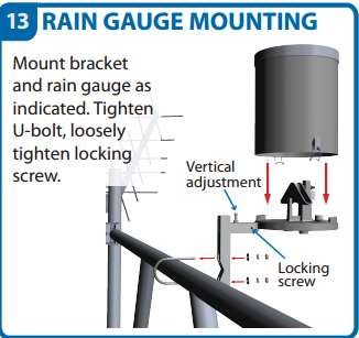
Contact Information

Canadian Headquarters:
1065 Henry Eng Place
Victoria, BC | V9B 6B2 | Canada
www.ftsinc.com

     Toll-free: 1.800.548.4264
     Local: 250.478.5561

     Technical support portal: http://support.ftsinc.com

     Email: service@ftsinc.com

                                                           Page 1/12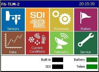
Table of Contents

Chapter 1                    GENERAL INFORMATION ......................................................................................................... 1
1.1      Components ........................................................................................................................................................... 1
1.2      Specifications .......................................................................................................................................................... 2

Chapter 2                    MOUNTING INSTRUCTIONS .................................................................................................... 3
2.1      Mounting Using a Base Plate ............................................................................................................................ 3
2.2      Mounting onto a Tri-Leg Assembly or Pole ................................................................................................ 4

Chapter 3                    SENSOR QUICK SET UP GUIDE ............................................................................................... 5
3.1      Setting Up the Rain Gauge ................................................................................................................................ 5
3.2      In-line Logging ....................................................................................................................................................... 7
3.3      Regular Logging .................................................................................................................................................... 8
3.4      Setting/Removing Rain Offset Values ........................................................................................................ 10
3.5      Changing the Setup .......................................................................................................................................... 10

Document Revision History .................................................................................................................................11

                                                                                                      i
Chapter 1 GENERAL INFORMATION
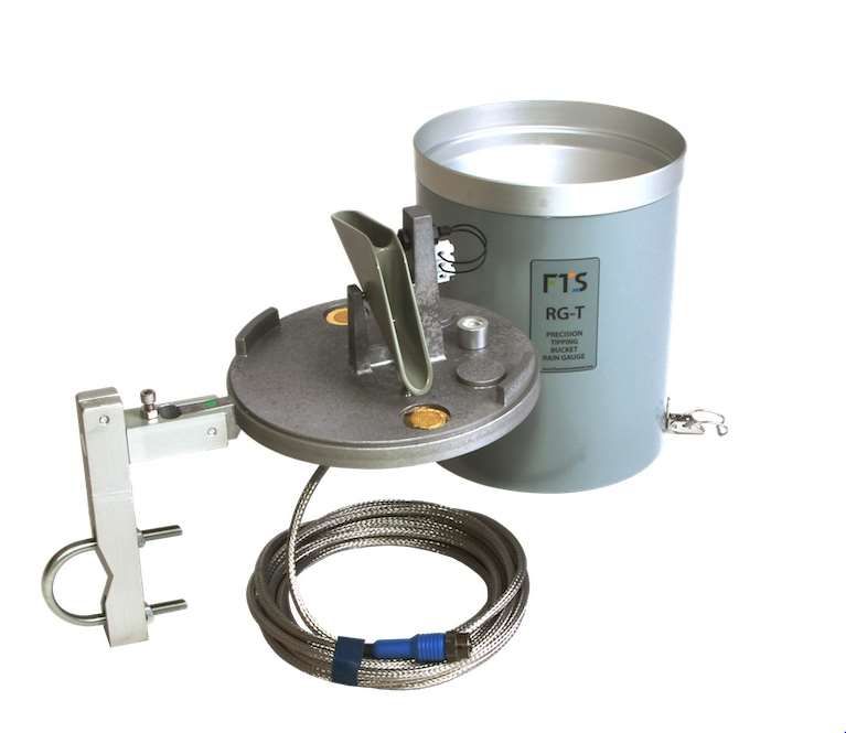
1.1 Components
The rain gauge consists of the pictured components. It will arrive with either the U-Bolt assembly arm
or the Base Plate assembly arm dependent on your order.
Housing
(screened funnel and tube casing)
Tipping Bucket
Adjustment
Screw #3
Adjustment
Screw #2
Bubble Level
Adjustment
Screw #1
Pivot arm
Sensor Cable
(stainless steel sheathed)
U-Bolt assembly arm
(for attaching to Tri-
Base Plate assembly
leg mount or pole) with spikes
(for ground mounting)
Figure 1-1: Rain Gauge Components
700-RGT Rev. 6 - 14 June 2016 Page 1/111.2 Specifications
Resolution: 0.01" per tip (0.254 mm) (optional calibration to 0.2 mm)
Accuracy: ±2% at 2" per hour (50 mm)
Cylinder dimensions: 10.5" x 8" diameter (257 mm x 203 mm)
Materials: Aluminum and stainless steel, engineered resin tipping
mechanism
Operating temperature F to 140 F (0°C to +60°C )
range:
Operating humidity range: 5% to 100%
Cable: 20 ft (6m) metal-clad armoured
Weight: 5.3 lbs (2.4 kg)
700-RGT Rev. 6 - 14 June 2016 Page 2/11Chapter 2 MOUNTING INSTRUCTIONS
2.1 Mounting Using a Base Plate
2.1.1 Equipment
In order to mount the rain gauge, you will need a mallet or hammer to drive the spikes into the
ground. If the terrain is unsuitable for using spikes, weights will be needed to place on the base plate
to provide stability.
If the rain gauge is being mounted on a wooden post or other flat structure, the base plate may have
to be pre-drilled with holes matching the desired attachment points. Bring sufficient screws and a
screwdriver or a drill and bits with which to mount it.
Levelling screws for the base plate assembly can all be loosened and tightened by hand.
2.1.2 Ground Mounting
1) Place the rain gauge on firm, level ground away from guy wires and brush to avoid drips and
debris from entering the funnel. It may also be mounted on a wooden post to raise it above
high grass or brush to minimize the amount of material which may enter the funnel.
2) Keeping the base as level as possible, anchor the gauge with spikes driven through the holes
in the base, or weights placed on the base. If mounting to a post, use spikes or screws to
secure the base to the post top.
3) Using the quick release clamps, remove the housing of the rain gauge, exposing the tipping
bucket and the bubble level.
NOTE! The tipping bucket is precisely calibrated. Rough handling may affect the
calibration of the rain gauge.
4) Carefully remove any restraints from the tipper bucket (ie: rubber band).
DO NOT handle or pull on the tipper bucket mechanism.
5) Loosen level adjustment screw #1( quick release clamp) and rotate the pivot arm until it is
approximately level.
6) Remove level adjustment screw #3 and loosen level adjustment screw #2. Raise level
adjustment screw #2 high enough so that the rain gauge assembly arm can slide into the slot.
7) Slide the rain gauge assembly’s arm into the pivot arm slot and replace level adjustment
screw #3 sufficiently to hold the assembly in place. Do not tighten.
8) Adjust the rain gauge assembly by adjusting the position of the pivot arm for horizontal
levelling, and adjusting level adjustment screw #2 up or down for vertical levelling.
9) Once the bubble leveller is centred, tighten level adjustment screws #1 and #3.
700-RGT Rev. 6 - 14 June 2016 Page 3/1110) Put the housing (funnel and tube section) back on the gauge and secure the latches.
11) Connect the sensor cable to the data logger.
12) Bury or otherwise arrange the cable to prevent a tripping hazard or inadvertent pulling on
the cable.
2.2 Mounting onto a Tri-Leg Assembly or Pole
2.2.1 Equipment
Very little equipment is needed to mount the rain gauge onto a Tri-leg assembly or horizontal pole.
An allen key for loosening and tightening the levelling screws is included in the pack up.
In addition to a 7/16” standard wrench for tightening the U-bolt, cable ties for securing the sensor
cable to the structure are all that will be required.
2.2.2 Pole Mounting
1) Determine where to place the rain gauge on the assembly. Ensure it is mounted away from
guy wires, and any overhanging equipment/structure which may cause a rain shadow or
direct drips into the funnel.
2) Place the V of the mounting arm against the pole and secure it using the U-bolt as shown.
Ensure the washer and the locking washers are placed on the bolt in that order before the nut.
2
Mount the arm
vertically
against the
pole using the
U-bolt.
Figure 2-1: Mounting the Assembly Arm
3) To mount the rain gauge assembly, follow steps 2 through 9 in section 1.2.2.
4) Once the rain gauge assembly is mounted, connect the sensor cable to the data logger.
5) Secure the sensor cable along the structure using the cable ties.
700-RGT Rev. 6 - 14 June 2016 Page 4/11Chapter 3 SENSOR QUICK SET UP GUIDE
This chapter will take you through the steps to set up the RG-T to an Axiom datalogger. It is meant as
a quick reference. Detailed instructions can be found in the Axiom User Guide and Axiom
Configuration Reference.
3.1 Setting Up the Rain Gauge
1) Connect the RG-T sensor cable to the data logger on the blue “Rain” port.
2) From the data logger’s home page, select the Sensors icon.
Figure 3-1: Home page
The next screen (SDI Sensor Mapping) will display the icons of the dedicated sensors which
are already added and set up.
3) To add the rain gauge, select the Add icon, then press on the Rain icon
Figure 3-2: Adding the Rain Gauge
700-RGT Rev. 6 - 14 June 2016 Page 5/114) The Rain Sensor Setup screen will be displayed
Figure 3-3: Rain Sensor Setup Screen
5) Edit the fields by pressing on the field box.
Sensor: The default name for the sensor is RNIN. You can change this if desired.
Units: The default setting is inches; however, it can be any unit desired. Typically
inches, mm, or counts are used.
Active: This box must be checked in order for the sensor to collect data
Tip Increment: This is the amount of rain measured by one tip of the rain gauge. The tip
bucket is calibrated to tip at 0.01 of an inch (the default setting).
The precision (number of decimal places) of the rain gauge output will be the same as the
precision of the tip increment. Trailing zeroes will not be recognized (ie: a tip increment of
0.01 and 0.010 will both render a precision of two decimal places).
IMPORTANT! Ensure the tip increment is converted to match the units selected for
accurate measurements.
Units Tip Increment
inches 0.01
cm .0254
mm 0.254
count 1
Auto Reset: if checked, allows the user to specify a rain counter reset date. The rain counter
is reset at the beginning of the day specified using the drop down date box.
Zero At Power Up: if checked, causes the datalogger to set the rain counter to zero every
time the datalogger is powered on.
700-RGT Rev. 6 - 14 June 2016 Page 6/11Rollover: if checked, causes the datalogger to reset the rain counter to zero once the
rollover value is surpassed.
6) Select OK .
i) If In-line Logging is enabled (from Station2) Check Enable Logging and if you want these values to be displayed in Current Conditions,
check the Current Condition box.
Figure 3-5: Editing In-line Logging
3) Select OK. Return to the Home Page
3.3 Regular Logging
If the In-line Logging option was not used, you must set up logging in order to view and collect data
on a variable. Regular logging provides the user the ability to create more complex logging than that
offered by the In-line Logging option.
1) From the Home page, select the Data icon and then the Setup Cog.
Figure 3-6: Regular Logging
2) The Logging intervals screen will be displayed. If there are already logging intervals set up
they will be seen here. Logging intervals created through the Data functions, as described here, are
displayed in blue. Logging intervals created using the In-line Logging feature are displayed in green.
700-RGT Rev. 6 - 14 June 2016 Page 8/11Figure 3-7: Logging Intervals
3) Press the Add icon, then the Edit icon. Set the desired logging interval and offset times.
NOTE: Logging intervals should not be less than the input measuring interval.
4) Scroll down the list of the Available Variables until you see the RNIN variable. Press it then use
Move Right Arrow to shift it to the Logged Variable field.
Figure 3-8: Logging Interval Setup Screen
5) Once done, select OK and the new Logging interval will be displayed in the Logging Interval
page. Return to the Home page.
700-RGT Rev. 6 - 14 June 2016 Page 9/113.4 Setting/Removing Rain Offset Values
From the Home page, select the Sensors icon, and then select the RNIN icon. The RNIN Sensor screen
will be displayed. From here offset values can be set or removed.
Set: Selecting this sets an offset value. The input value will be the base measurement to which
subsequent tip increments will be added (ie: if the value is set to 1.0 mm, the next tip will result in a
measurement value of 1.254 mm – see the following figure).
Figure 3-9: Setting Offset Values
Zero: Selecting this will remove the offset value and return the displayed measurement to zero.
3.5 Changing the Setup
From the Home page select Rain. Select the Set up Cog to bring you to the Rain Sensor Setup
page. Press on the Edit icon and make desired changes.
700-RGT Rev. 6 - 14 June 2016 Page 10/11Document Revision History
Revision Date Description
1 10 May 2007 Original release
Format change. Added pictures, direction for mounting to a pole
2 2 Apr 2015
and sensor quick set up guide.
3 10 Apr 2015 Expanded Logging information. Labelled figures.
4 20 May 2015 Added specifications
5 13 Oct 2015 New Format
Corrected Specifications (weight) and capitalized the tag line
6 14 Jun 2016
(cover page).
700-RGT Rev. 6 - 14 June 2016 Page 11/11You can also read