Ring-Embedded Micro-Power mm-Sized Optical Sensor for Accurate Heart Beat Monitoring - Senbiosys
←
→
Page content transcription
If your browser does not render page correctly, please read the page content below
Date of publication xxxx 00, 0000, date of current version xxxx 00, 0000.
Digital Object Identifier 10.1109/ACCESS.2021.DOI

Ring-Embedded Micro-Power mm-Sized
Optical Sensor for Accurate Heart Beat
Monitoring
ASSIM BOUKHAYMA, ANTHONY BARISON, SERJ HADDAD, AND ANTONINO CAIZZONE.
Senbiosys SA, Neuchatel, CH-2000 Switzerland
Corresponding author: Assim Boukhayma (e-mail: assim.boukhayma@senbiosys.com).

   ABSTRACT This paper presents a wearable optical health monitoring device embedding a monolithic
   sensor chip with newly designed pixels, and an optical module optimized for photoplethysmography (PPG).
   The monolithic optical sensor at the heart of this device implements an array of novel pixels designed
   specifically for PPG and featuring a quantum efficiency (QE) as high as 85 %. The sensor readout chain, as
   well as the logic circuits, implements low power design techniques leading to only 60 µA current consumption
   at 122 Hz operation frequency, including digital communication. Thanks to the high QE and optical module
   optimization, medical grade PPG recordings are enabled with less than 10 µA emitter current. The optical
   sensor is embedded in an ergonomic ring device together with system electronics in order to enable in-field
   test of beat detection accuracy on 7 subjects. The ring device detects correctly 97.87 % of the beats on a
   total of 72.21 hours of recording. The inter-beat interval (IBI) estimation from these recordings features a
   mean absolute error (MAE) as low as 8.10 ms. This performance is achieved with less than 70 µA current
   consumption at the level of the PPG module.

   INDEX TERMS CMOS image sensor, heart beat detection, low power integrated circuit, monolithic optical
   detector, photoplethismography sensor, wearable electronics.

I. INTRODUCTION                                                             benefiting from the PPG technology. Among them smartrings
                                                                            are getting popularity, particularly in the sleep monitoring
       EMOTE health monitoring, based on wearable-
R      integrated sensors, provides these days more and more
alternatives to standard healthcare practices. Indeed, the
                                                                            application [2], thanks to the longer lifetime coming from the
                                                                            PPG-centered usage. In addition, the PPG signal quality is
                                                                            biased by the body location of the PPG sensor itself, and, in
modern society suffers from an increase in cardiovascular-                  this regard, the finger is considered as one of the best locations
diseases (CVDs) case, resulting from the population ageing                  in terms of PPG signal quality [3]. This ultimately results into
and the growing obesity rates. This imposes huge economical                 better vitals’ extraction and lower power consumption.
implications and, as a matter of fact, is calling out for cost-             A PPG signal is obtained by shining light from one or
effective and reliable wearable health monitoring devices.                  more LEDs, at a given wavelength, into a human tissue,
Heart rate monitoring by the means of optical transduction                  e.g. finger, wrist, ear lobs. Wavelengths from visible to near-
has revolutionized the smartwatches and fitness band segment                infrared are used. As shown in Fig. 1, a photodetector (PD)
and proven the huge implication of those devices to improve                 detects the light reflected from the tissue and transforms
people’s lifestyle and wellness. The science and sensing                    it into a photogenerated current. The PPG signal, i.e. the
scheme behind the optical heart rate monitors is the so called              photogenerated current, features two different components: a
Photoplethysmography (PPG). It has been proven that this                    large quasi-DC component corresponding to the light diffusion
technology enables non-invasive monitoring of vital signs well              through tissues and non-pulsatile blood layers, and a small
beyond the heart rate, including the blood oxygen saturation,               AC part due to the diffusion through the arterial blood. The
the respiration rate, and the arterial blood pressure [1]. The              AC component is typically between 0.2% and 10% of the DC
latter, as a matter of fact, is gaining huge interest these days.           one, depending on several factors including the body location
Despite the PPG sensors have appeared at first in smartwatches              and the body temperature [4]. The ratio between the AC and
and fitness bands, lately, more and more types of wearables are

VOLUME X, 2021                                                                                                                              1
Boukhayma et al.: Ring-Embedded Micro-Power mm-Sized Optical Sensor for Accurate Heart Beat Monitoring

                                                         diastole systole

                                        optical signal
             finger                                                             AC
                                                                                                                                           Digital
     vein                                                 non-pulsatile blood                                                              control
    artery                                                                      DC
                                                               tissue                                           Macro-pixel array
                      sensor chip LED                                                                                                      Clks &
                                                                            time                                                            refs.
FIGURE 1. Sensor set-up for a PPG measurement and the DC and AC                                                                            Amplifier
components of a PPG signal.
                                                                                                                                            ADC

                                                                                                                                             LED
the DC components is usually referred to as Perfusion-Index
                                                                                                                                             drive
(PI). Enhancing the PI for a given power and dynamic range                                                         FIFO              SPI
budget is one of the most severe challenges when it comes to
engineering a PPG sensor. Indeed, the majority of the medical                           FIGURE 2. Die micrograph showing the 2.5 mm by 2.5 mm sensor main
                                                                                        building blocks integrated with pixels array.
information is carried by the tiny AC component.
 Despite the great interest behind the PPG technology, state-of-
the-art (SOA) PPG sensors are still limited by the LEDs power
consumption, which usually dominates the PPG sensors’                                   PPG module into a smartring in order to ensure ergonomics.
power drill down. Indeed, SOA sensors still leverage a quite                            The performance measurements of the optical module are
standard design paradigm, relying on off-chip photodiodes                               shown in Section V. Section VI reports how the smartring
and standard circuitry, the latter very often based on a                                data are processed to achieve accurate heart beat monitoring.
transimpedance-amplifier (TIA). This design paradigm often                              Section VII highlights the advantages of the proposed PPG
limits the exploitation of these sensors in the remote health                           monolithic chip and module in the smartrings use case. Finally,
monitoring, because of a still fairly large power consumption.                          Section VIII concludes the paper.
Pinned-photodiodes (PPDs) are today the key ingredients of
CMOS image sensors (CIS), thanks to their large sensitivity                             II. A MICRO-POWER MM-SIZED MONOLITHIC PPG
and extremely low-noise operations [5] [6]. It has been shown                           SENSOR
in [7], [8], [9], [10] that the excellent performance of a PPD                         The use of a monolithic chip for a ring device reduces the
makes it particularly interesting for the PPG application.                             integration constraints. Indeed, it reduces the number of
Indeed, it is possible to reduce the PPG sensor LED average                            discrete elements that need to be placed on a flexible, or
current consumption to a few µA, still achieving very high                             curved, platform. The chip presented in [11] shows a good
signal fidelity, the latter being key for any vitals’ extraction.                      example of the miniaturization level that can be achieved
We have recently presented a monolithic micro-power mm-                                thanks to the implementation of a monolithic CIS technology.
sized PPG sensor integrating an array of newly designed                                The latter implementation targeted an ear worn device. The
pixels, featuring high quantum efficiency (QE) up to 800 nm.                           PPG signal depends dramatically on the body location. The
The latter was optimized to operate on an ear worn device                              finger PPG PI is more dependent on ambient temperature
(earbud) with a very compact chip and optical module [11],                             drop compared to ear PPG, where the skin is less affected by
demonstrating medical grade performance for heart beat                                 hypothermia, unlike the limbs. Hence, in contrast to [11], a
detection. This paper extends this work and shows that this                            larger pixel array is needed to collect more signal in the case of
technology can be exploited in another wearable PPG use case:                          a PI drop. Fig. 2 shows a micrograph picture of the monolithic
the smartring. In this regard, a new chip featuring a larger                           chip designed for finger PPGs. This chip is fabricated in a
size together with a larger optical module are specifically                            180 nm CIS four metal process and features a size of 2.5 mm
designed for this ring application. A medical grade heart beat                         by 2.5 mm. Similarly to [11], this PPG sensor is a stand alone
detection with less than 10 µA LED current has been achieved                           chip embedding its own oscillators, LED drivers with two time
thanks to the efficient coupling of the optical module into an                         division multiplexed channel to operate two LED wavelengths,
ergonomic and compact ring. As a matter of fact, the different                         an integrated array of dedicated pixels, together with a low
optimization layers enabling this performance, in terms of                             noise analog readout chain. The latter includes the analog to
optical module and wearable system, are also described. This                           digital conversion (ADC). For the communication, the chip
work is organized as follows: Section II briefly overviews the                         encompasses a 128 words first-in-first-out (FIFO) register,
working principle behind the proposed PPD pixels and also                              and a serial peripheral interface (SPI) communication unit.
introduces the micro-power mm-sized PPG sensor. Section III                            The photosensitive area embeds an array of pixels exploiting
presents how the micro-power PPG chip is integrated together                           PPD technology to ensure a maximum QE and low noise
with the LEDs, module-wise, in order to enhance the PPG                                performance.
performance. Section IV describes the strategy to integrate the                        The global architecture of the sensor is depicted in Fig. 3,
2                                                                                                                                                      VOLUME X, 2021
Boukhayma et al.: Ring-Embedded Micro-Power mm-Sized Optical Sensor for Accurate Heart Beat Monitoring
together with a simplified timing diagram. The pixel features a
Out
two-tap PPD scheme with deep epitaxial layer, that is detailed
VDD RST TX RST VDD
in [10]. This offers a good QE, up to the near-infra-red (NIR) λG λR
spectra. The p+np structure of the PPD integrates the electrons N+ P+ N+ N+
sink e- read
N
generated from the photons impinging on the PPD depleted VDD_LED (3.3V)
h+
area. The reset tap (RST) dumps the charge integrated outside weak epitaxial P
the signal integration window. The transfer tap (TX) transfers P substrate
the charge integrated during the sensing windows. A double
sampling scheme is adopted in order to mitigate the ambient LED
light component. All the pixels of a same column share their drivers
transferred charge on the same sense node (SN). The SNs are 500 kHz
TX TX
oscillator pixel pixel
connected to a switchable parallel capacitance that enables RST RST
the extension of the dynamic range, if needed.
The pixels feature the same well density of 3 · array pixel pixel
105 electrons/pixel as in [11]. In this wok, the array is designed control Cext Cext
to reach a higher DC signal-to-noise-ratio (SNR) of 96 dB to native SF native SF
cope with the more challenging PI variation of the finger PPG. control logic
Ф1 Ф2 Ф1 Ф2
Under the assumption of shot noise dominance, the number of
Фavg
photo-electrons required to reach 96 dB is 4 · 109 . Therefore, 3.3V
the array encompasses 16384 pixels, split equally between macro-pixel
1.8V
512 macro-pixels (MP). This array is four times larger than Gain control
amplifier
the one presented in [11].
50 MHz ADC control
The SNs voltage level is readout thanks to source follower oscillator logic ADC
stages (SFs), exploiting native transistors for a maximum 14bits
SPI 128 FIFO
voltage swing. Two sample and hold stages are then used for chip
storing the ambient and signal levels and, at the same time,
allowing for the averaging of those sampled values by the (a)
means of a charge sharing mechanisms over the whole array. LED
This process reduces dramatically the noise contribution of pulse
RST
the active SF stages. It also plays the role of buffering the TX
signal to the input of the variable gain amplifier. The latter Ф1
amplifies the ambient light free signal samples to a low power Ф2
14 bit ADC, whose features are described in [9]. Фavg
As shown in Fig. 3, the chip embeds two oscillators providing amp diff.
amp.
a 500 kHz and a 50 MHz clocks. The slow clock runs all
ADC ADC.
the time and feeds the main control logic block. The latter
governs the sampling frequency and generates the timing (b)
phases for the pixel array and associated stages, namely, the
FIGURE 3. (a) A block diagram of the sensor depicting the macro-pixels array,
SFs, the sample and holds, and averaging stages. The control the subtracting amplifier with ADC, and (b) corresponding timing diagram.
logic also governs the LED drivers and the amplifier. The fast
clock is only used during the analog-to-digital conversion. In
other words, power gating is used whenever the fast clock is
not needed. Similarly to the fast clock, the power supply is power consumption [µW] ADC, amplifier, 50MHz logic
also gated in order to optimize the chip power consumption. array
Fig. 4 depicts the drill down of the chip power consumption 500 kHz logic
over time. The array circuit blocks are powered during the 306
light integration and sampling, only. Once the samples are
averaged, the amplifier and ADC are then powered to operate 165
the conversion.
5
time
III. OPTICAL MODULE OPTIMIZATION
1/fs
The optical module consists of the emitters (LEDs), the sensor
0.3 ms 2.6 ms
chip, as shown in II, and an optical housing. The latter ensures
a good optical coupling with the skin and at the same time
a low direct light cross-talk between the sensor chip and the FIGURE 4. Sensor chip power consumption.
LEDs. It is obvious that the vertical distance between the
VOLUME X, 2021 3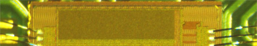
Boukhayma et al.: Ring-Embedded Micro-Power mm-Sized Optical Sensor for Accurate Heart Beat Monitoring
1.0
530 nm w
660 nm
0.8 Typ.
Dim.
[mm]
LED2 L
D 19
LED1
Relative PI [-]
0.6 W 7.9
W t 3.8
f 1
0.4
Δy1 b 1.22
2b/D 12.8%
0.2 Δy2
BLE + PMU + MCU
f
0.0 Flex
1.5 2.0 2.5 3.0 3.5
PD-LED Horiz. Distance [mm]
4.0 4.5
Optical
t D
FIGURE 5. Simulated relations between relative PI and sensor-to-emitter
module
(PD-LED) distance at 530 nm and 660 nm.
b
2 x 15 mAh Batteries
Sensor chip under
Red LED Green LED transparent resin FIGURE 7. Isometric and orthogonal views of the ring, including teardown of
the electronic system.
with the LED-sensor distance, but the number of received
photons actually decreases. It is known that the optical decay
follows an exponential trend. Hence the increase of PI with
respect to δy is much weaker than the optical signal loss
due to the LED-sensor distance. Hence, we have set δy to
the minimum possible distance. Fig. 6 shows the resulting
optical module. LED1 is an OSRAM CT DELSS1.12 with
nominal wavelength at 530 nm, while LED2 is an OSRAM
Optical barrier Flexible PCB
CH DELSS1.22 emitting at 660 nm. The wire bonding, the
LEDs package and the minimum wall thickness set the
FIGURE 6. Photograph of the optimized optical module embedding LEDs, minimum distance between the sensor and the LEDs, which
sensor chip covered by transparent resin, and optical barrier mounted on a
flexible PCB. is equal to 2.8 mm, center to center. Hence we have set
the distance between the LED1 and the sensor (∆y1 ) at its
minimum of 2.8 mm. LED2 is placed at ∆y2 equal to 4 mm,
skin and both the LEDs and the sensor must remain as short which is the closest possible, i.e. placing it right next to LED1.
as possible to minimize the optical signal loss. However the The resulting module size (W · L · H) is 3.8 · 7.1 · 0.6 mm3 .
horizontal distance separating the LEDs and the sensor chip
requires a deeper thought. The optimization of the LED-sensor
distance goes through a good understanding of the light-tissue IV. THE RING SYSTEM DESIGN
interaction. In this work, we have reused the optical skin A wearable ring was designed to embed the PPG module
model presented in [11]. This model considers a seven layer as in Fig. 6. Fig. 7 shows isometric and orthogonal views of
structure and it has been proven sufficiently accurate to model the design, and a teardown image of the system, showing
primary effects of photon-skin interactions [12], [13], [14]. the PPG module connected to the microcontroller unit and a
As shown in [11], TracePro® is used to simulate the non- set of custom-shaped batteries. The ring diameter is chosen
pulsatile (DC) and pulsatile (AC) components of the optical in the range 18 mm to 20 mm which has allowed to fit all
signal. Fig. 5 shows the simulated relation between the relative the population in our study. The ergonomics of the ring is
PI (AC/DC) and the sensor-LED distance (δy), for green primarily dependent on the diameter (D) and secondly upon
(530 nm) and red (600 nm) LEDs. The PI increases with δy the thickness (t), width (w), internal filleting radius (f ) and
for both wavelengths. However, the green light comes with the position of the sensor (b). The thickness of the ring is
better PI and features more sensitivity to δy, thanks to the optimized to provide inter-digits comfort and to preserve
intrinsic larger absorption. structural strength based on design guidelines for the chosen
The SNR is proportional to the PI and the number of photons 3D printing process and material [15]. The combination of
received by the sensor [9]. Fig. 5 shows that the PI increases w, f and b determines the mechanical strain of the skin.
4 VOLUME X, 2021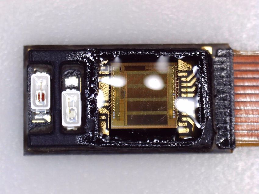
Boukhayma et al.: Ring-Embedded Micro-Power mm-Sized Optical Sensor for Accurate Heart Beat Monitoring

TABLE 1. Sensor characteristics.
                                                                                                                     Raw DC SNR
 Device PPG module               Application      Size         consumption                    80
                                                                                              75
 This              Monolithic      Heart beat     width:       2.5 mA without
 work              PPG     sensor, monitoring     7.9 mm       duty cycling                   70

                                                                                   SNR [dB]
                   true green and                 thickness:                                  65
                   red LEDs                       3.8 mm
                                                                                              60
 [16]             discrete PD, Surgical pleth     width: 10 mm 3 mA
                  AFE, hyper red index            thickness:                                  55
                  LEDs                            2 mm
                                                                                              50
 [2]              discrete PD, Sleep              width:       not reported                        0   2000   4000   6000    8000 10000 12000 14000 16000
                  AFE, infrared monitoring        7.9 mm                                                                    Output
                  LEDs                            thickness:
                                                  2.55 mm
                                                                                FIGURE 9. Measured SNR as a function of the sensor output obtained by
                                                                                operating the optical module, composed of the monolithic sensor and LED
                                                                                emitters, in loop-back mode. The SNR measurement takes into account all
           100                                                                  noise sources including shot noise, readout electronic noise, and the noise
            90                                                                  generated at the level of the LEDs.

            80
            70
            60                                                                  V. OPTICAL MODULE MEASUREMENTS
 EQE [%]

            50                                                                  Fig. 8 shows the measured effective QE (EQE) of the pixel.
            40
                                                                                The proposed pixel features a weak P epitaxial depth of 12 µm.
            30
                                                                                The proposed pixel demonstrates a clear advantage on the QE
            20
                                                                                with respect to standard epitaxy pixels [8], especially in the
            10
                                                                                NIR region. In fact, the EQE curve is close to 85% up to
             0
                 400     500      600         700       800    900       1000
                                                                                800 nm.
                                        Wavelength [nm]                          Fig. 9 shows the SNR, measured on the sensor output raw data
                                                                                (without digital filtering), in loop-back mode, as a function
FIGURE 8. Measure EQE of two versions of the PPD based pixel dedicated          of the output mean value. This measurement is obtained by
for PPG with two weakly doped epitaxial layer depths. The measurement
shows a better EQE for the pixels implemented in the presented work (18 µm
                                                                                exposing the module, composed of the sensor and LEDs,
epitaxial) particularly towards the NIR region.                                 to a stable reflector. The emitting LEDs driving current is
                                                                                increased progressively resulting in an increase of the light
                                                                                intensity reflected on the monolithic sensor. Each point is
                                                                                obtained by measuring the noise and the mean values of
According to previous experimental observations, we have
                                                                                the output, at a given LED driving current. In this way, this
found an optimal point between the user’s comfort and the
                                                                                measurement of the SNR embeds not only the noise generated
PPG signal quality resulting from the pressure onto the
                                                                                in the detection and readout process, but also the noise of
skin at the area of optomechanical coupling of the sensor.
                                                                                the LED drivers and LED devices as well. The whole system
In this study, a flat edge in the inner part of the ring is
                                                                                can go up to 75 dB, without digital filtering. Since the PPG
found to be at an optimal point when the ratio 2b/D is set
                                                                                signal is anyway digitally filtered during the processing, the
at 12.8%. A functional prototype, Fig. 10, is 3D printed in
                                                                                maximum SNR increases to 85 dB, after band limiting the
stereolithography, because of its advantages such as being
                                                                                signal between 0.1 Hz and 4 Hz by the means of a second
cost-effective and also featuring greater resolution for smaller
                                                                                order Butterworth filter. The presented optical module features
features. A nylon-based material, EOS PA2200®, is selected
                                                                                similar performance with respect to the sensor presented
because robust, flexible, stable for long periods of time and
                                                                                in [11]. Indeed, the presented sensor features a larger pixel
biocompatible under EN ISO 10993-1.
                                                                                array but exploits the same amplifier and ADC design. The
Table 1 compares the design of the presented ring with recent
                                                                                amplifier and ADC limit the performance in terms of SNR.
SOA. The presented ring offers a substantial advantage in
                                                                                Though, the larger pixel array enables collecting more signal
terms of size and power consumption. Note that 2.5 mA is
                                                                                photons compared to [11], which compensates for the more
the current consumed of the whole ring when the Bluetooth-
                                                                                challenging body location.
low-energy (BLE) and the micro-controller unit (MCU) are
                                                                                Tab. 2 shows a summary of the main chip characteristics and
always on. For this study, we needed the ring to emit the data,
                                                                                performance metrics in comparison with recent state of the
via BLE, real time without any interruption to the computer.
                                                                                art. The introduced chip presents a monolithic solution that
We expect this current consumption to be reduced by an order
                                                                                stands out in terms of silicon area, QE, power consumption
of magnitude, at least, if the data transmission is duty cycled.
                                                                                and ambient light rejection, while embedding a 128 FIFO
                                                                                register, internal oscillators, and serial peripheral interface
VOLUME X, 2021                                                                                                                                                5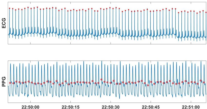
Boukhayma et al.: Ring-Embedded Micro-Power mm-Sized Optical Sensor for Accurate Heart Beat Monitoring

                                                                               TABLE 2. Sensor characteristics

                                                                                Parameter         This work         [17]              [18]

                                                                                Monolithic        yes               no                yes
                                                                                (integrated
                                                                                photo-detector)
                                                                                Process           180 nm CIS        180 nm            65 nm CIS
                                                                                Voltage supply    3.3/1.8 V         3.3/1.2 V         1.8/1 V
                                                                                Area              5.76 mm2          7 mm2             5.5 mm2
                                                                                Integrated FIFO yes (128 words)     no                yes (64 words)
                                                                                and SPI/I2C
                                                                                Max. sampling 500 Hz                2048 Hz           20 Hz
                                                                                frequency
                                                                                Max. dynamic 90 dB                  119 dB            90 dB
                                                                                range
                                                                                ADC resolution    14 bit            14 bit            16 bit
                                                                                Current           60 µA @ 122 Hz 74 µA @ 522 Hz 24 µA @ 20 Hz
                                                                                consumption       including      excluding      including digi-
                                                                                                  digital        digital        tal
FIGURE 10. Photograph of the ring device embedding the presented                Ambient light 64 dB        @ not reported             direct 46 dB be-
monolithic sensor and its optimized optical module.                             cancellation  10 Hz      with                         low 120 Hz
                                                                                              20 dB/frequency
                                                                                              decade decrease

                                                                               A. IMPORTANCE OF ACCURATE BEAT DETECTION
                                                                               Heart-rate variability (HRV), which is a physiological phe-
                                                                               nomenon that represents the change in the intervals of the
                                                                               consecutive heart-beats, is a very important index for the
                                                                               healthiness of the cardiovascular system. It is a measure of
FIGURE 11. Example of a raw PPG recording obtained from the finger of a
subject wearing the presented ring device.
                                                                               the cardiac activity that estimates the autonomous nervous
                                                                               system (ANS) balance [19]. As a matter of fact, HRV is
                                                                               closely associated with the overall physical fitness and the
(SPI) protocol communication unit. These features are key                      psychological well-being of an individual and it is used
for efficient integration in a wearable device, especially when                for stress and recovery analysis [19]. Since the outbreak of
paired with an optimal optical module design, as previously                    the COVID-19 pandemic the HRV data is becoming very
described.                                                                     crucial and is being heavily analyzed to study the effect of
In order to demonstrate the performance of the ring system in                  the COVID-19 on the mental health and the stress levels of
terms of PPG signal quality, Fig. 11 shows an example of a                     individuals. HRV is also applied for sleep monitoring [20], and
high SNR raw PPG signal recorded using the presented ring                      different types of arrhythmia detection [21], [22]. Therefore,
device. This PPG signal is recorded on the finger of a male                    it goes without saying that accurate, reliable, and continuous
subject wearing the ring as shown in Fig. 10. The recorded                     HRV monitoring is of utmost importance. An accurate HRV
PPG signal features an SNR of 57 dB with a PI of 9%, while                     analysis, however, requires an efficient beat-to-beat heart rate
the sensor consumes less than 70 µA, including both the LEDs                   detection [23], [24]. The classical method (the gold standard)
and the monolithic sensor chip.                                                of heart rate (HR) and HRV monitoring is using electrocardio-
The prototyped wearable ring led to further ex-vivo studies of                 graphy (ECG) devices. The drawback of the ECG recorders
the PPG signal at the finger location, the content of which is                 [25], [26] however is that they are highly uncomfortable and
the object of the next session.                                                vulnerable to poor skin contact and dry skin conditions, which
                                                                               makes them unpleasant for long term recordings. As such, new
                                                                               solutions and methods that provide comfortable, unobtrusive,
                                                                               and inexpensive solutions are becoming highly attractive. Of
VI. RING SYSTEM VALIDATION FOR HEART BEAT
                                                                               these solutions and technologies, PPG is the most promising
MONITORING
                                                                               and favorable to provide low cost and agreeable alternative
In this section, the system-level performance of the presented
                                                                               for HR and HRV monitoring.
ring device is evaluated, on several subjects, for heart beat
monitoring.
6                                                                                                                                           VOLUME X, 2021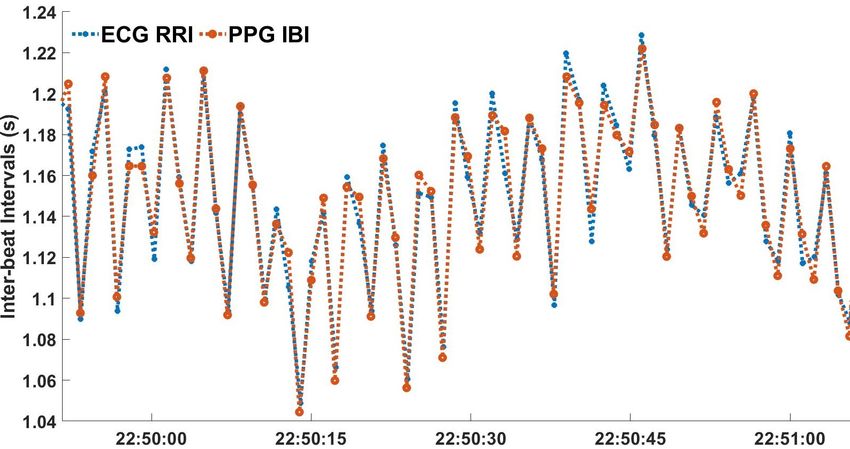
Boukhayma et al.: Ring-Embedded Micro-Power mm-Sized Optical Sensor for Accurate Heart Beat Monitoring

TABLE 3. The statistics of the reference RR intervals.                        TABLE 4. The beat detection performance.

            Number of RRI’s                          213072                               Correctly Detected Beats               208539
            Mean ± SD (ms)                        1040 ± 170                              Correct Beats (%)                      97.87
            pNN50 (%)                                    29.40                            Missed Beats (%)                        2.13
            pNN20 (%)                                    71.13                            Extra Beats (%)                         1.40

                                                                              TABLE 5. The performance of the IBI Estimation.

                                                                                                  MAE (ms)                8.10
                                                                                                  ME (ms)                 0.24
                                                                                                  RMSE (ms)              13.97
                                                                                                  MAPE (%)                0.80

                                                                              Fig. 12(a), we present plots of ECG and PPG recordings. The
                                                                              plots include (in red labels) the detection of R-peaks of the
                                     (a)
                                                                              ECG signal and the detection of the maximum up-slopes of
                                                                              the PPG signal. These points are used to generate the ECG-
                                                                              based RR intervals and the PPG-based IBI values, depicted in
                                                                              Fig. 12(b).
                                                                              Table 3 summarizes the statistics of the reference RRI values.
                                                                              The mean RRI value is 1.04 ± 0.17 s, which means that on
                                                                              average the participants have HR values less than < 60 beats
                                                                              per minute. Moreover, the average HRV of the participants
                                                                              can be considered to be fairly high with a pNN50 and pNN201
                                                                              values of 29.40% and 71.13%, respectively.

                                                                               C. PERFORMANCE EVALUATION
                                     (b)                                      The performance of the IBI detection algorithm using the
FIGURE 12. (a) A plot of ECG and PPG signals with R-peak and maximum          ring is summarized in Table 4. The results show that the
up-slope detection (red labels), respectively. (b) Corresponding ECG-based    percentage of the correctly detected beats is 97.87%. On the
RR intervals and PPG-based IBI’s.
                                                                              other hand, the percentage of the extra beats is only 1.40%.
                                                                              Table 5 summarizes the IBI estimation accuracy of the ring
B. BEAT DETECTION USING THE RING                                              PPG with a mean absolute error (MAE) of 8.10 ms, a mean
                                                                              error (ME) of 0.24 ms, a root mean square error (RMSE)
In what follows, we present a study that we have performed
                                                                              of 13.97 ms, and a mean absolute percentage error (MAPE)
to examine the beat-to-beat detection accuracy of using the
                                                                              of 0.80%. As shown in Table 6, these beat detection and
PPG signal recorded by the presented ring device. Seven male
                                                                              IBI estimation performance metrics improve for sleep/night
subjects with a mean age of 34.29 ± 5.28 years participate in
                                                                              recordings because of the absence of motion artifacts.
the study. In total, 43 day and night recordings are performed
with a total duration of 72.21 hours: 37.10 hours of sleep and
35.11 hours of wake recording. The participants are asked to
                                                                               VII. DISCUSSION
wear the ring in the middle finger. The sampling frequency
                                                                              The proposed monolithic PPG sensor design can trigger the
of the ring is set to 122 Hz and the driving current of the
                                                                              advent of more and more smartrings. Indeed, on one hand,
LED is set to 4.1 mA. For the reference ECG recordings,
                                                                              the finger PPG exhibits a fairly large PI with respect to other
the Shimmer3 Consensys ECG development kit is used to
                                                                              body locations, e.g. the wrist, leading to intrinsically better
monitor 4 ECG channels. The sampling frequency for the
                                                                              vitals extraction at lower power operations [1], but on the
ECG recordings is set to 1024 Hz.
                                                                              other hand, it can also suffer from some challenges. Among
 To extract the IBI values from the ring PPG signals, we have
                                                                              them, the motion-artifacts (MAs) and the PI reduction caused
used the Senbiosys proprietary IBI detection software. On the
other hand, to extract the RR intervals (RRI) from the ECG                      1 pNN50 and pNN20 denote the percentage of the RR intervals with a
signals, the ConsensysPRO Software version 1.6.0 is used. In                  successive difference exceeding 50 ms and 20 ms, respectively.

VOLUME X, 2021                                                                                                                                  7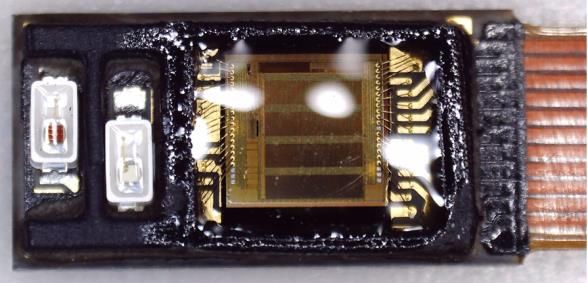
Boukhayma et al.: Ring-Embedded Micro-Power mm-Sized Optical Sensor for Accurate Heart Beat Monitoring

TABLE 6. The beat detection-estimation performance: wake vs sleep.             way for further miniaturization with advanced optical module
                                                                               packaging. The combination of further miniaturization and
                                                                               reduced power consumption eases the integration of a plurality
                                        Wake      Sleep
                                                                               of integrated independent PPG modules in a same ring device.
                 Correct Beats (%)      97.30     98.30                        This proposed wearable optical heart beat monitoring system
                 Missed Beats (%)       2.70      1.70                         shows a promising potential for wellness and medical health
                 Extra Beats (%)        1.92      1.00                         monitoring thanks to the ease of use, non-evasiveness and long
                 MAE (ms)               8.32      7.94                         battery life. Further clinical studies shall be performed to bring
                 ME (ms)                0.79     −0.17                         this wearable technology to the medical heath monitoring
                 RMSE (ms)              15.96     12.48                        market.
                 MAPE (%)               0.80      0.81
                                                                               REFERENCES
                                                                                [1] A. Caizzone, An Ultra Low-Noise Micropower PPG Sensor. PhD Thesis,
                                                                                    EPFL, 2020.
                                                                                [2] Ouraring, https://ouraring.com, accessed in 2021.
by hypothermia are among the toughest [27].                                     [3] E. Tur, M. Tur, H. I. Maibach, and R. H. Guy, “Basal perfusion of
PPG spatial diversity, in essence the distribution of many PPG                      the cutaneous microcirculation: Measurements as a function of anatomic
sensors around the sensing point, has proven to be particularly                     position,” Journal of Investigative Dermatology, vol. 81, no. 5, pp. 442
                                                                                    – 446, 1983. [Online]. Available: http://www.sciencedirect.com/science/
effective in the smartwatches segment, to counterbalance                            article/pii/S0022202X15432312
the effect of MAs and lower perfusion [1]. The authors                          [4] J. G. Webster, Design of Pulse Oximeters. Bristol, PA, USA: Philadelphia:
believe that the (smart) rings can also benefit from similar                        Institute of Physics Pub., 1997.
                                                                                [5] A. Boukhayma, Ultra Low Noise CMOS Image Sensors. Springer, 2018.
considerations, which will help to cope with the above-                         [6] A. Boukhayma, A. Peizerat, and C. Enz, “A sub-0.5 electron read
mentioned challenges. That said, unlike a smartwatch, the                           noise vga image sensor in a standard cmos process,” IEEE Journal of
miniaturization constraints around a smart ring impose some                         Solid-State Circuits, vol. 51, no. 9, pp. 2180–2191, Sep. 2016, DOI:
                                                                                    10.1109/JSSC.2016.2579643.
limits, in terms of number of integrated PPG sensors, unless                    [7] A. Boukhayma, A. Caizzone, and C. Enz, Health monitoring device. US
the PPG sensor itself becomes particularly miniaturized. The                        patent US20200205680A1, 2017.
monolithic PPG sensor proposed in this work paves the way                       [8] A. Caizzone, A. Boukhayma, and C. Enz, “A 2.6µW Monolithic CMOS
                                                                                    Photoplethysmographic Sensor Operating with 2µW LED Power,” in 2019
for such an approach thanks to the low power consumption                            IEEE International Solid- State Circuits Conference - (ISSCC), Feb 2019,
and enhanced miniaturization.                                                       DOI: 10.1109/ISSCC.2019.8662404, pp. 290–291.
                                                                                [9] A. Caizzone, A. Boukhayma, and C. Enz, “A 2.6 µw monolithic
VIII. CONCLUSION
                                                                                    cmos photoplethysmographic (ppg) sensor operating with 2 µw
wearable optical heart beat monitoring sensor integrated in a                       led power for continuous health monitoring,” IEEE Transactions on
                                                                                    Biomedical Circuits and Systems, vol. 13, no. 6, pp. 1243–1253, 2019.
ring. The device embeds a monolithic optical sensor exploiting                 [10] A. Boukhayma, A. Caizzone, and C. Enz, “An ultra-low power ppg
a CIS process. It encompasses dedicated pixels featuring an                         and mm-resolution tof ppd-based cmos chip towards all-in-one photonic
almost flat QE response on the whole visible range, while still                     sensors,” IEEE Sensors Journal, vol. 19, no. 24, pp. 11 858–11 866, 2019.
                                                                               [11] A. Boukhayma, A. Barison, S. Haddad, and A. Caizzone, “Earbud-
exhibiting good NIR response. The dedicated pixels array is                         embedded micro-power mm-sized optical sensor for accurate heart beat
combined with low power design and CMOS integration to                              monitoring,” IEEE Sensors Journal, pp. 1–1, 2021.
result in an ultra-low power and miniaturized sensor chip.                     [12] V. V. Tuchin, S. Utz, and I. Yaroslavsky, “Tissue optics, light distribution,
                                                                                    and spectroscopy,” Optical Engineering - OPT ENG, vol. 33, no. 10, pp.
The advantages obtained thanks to the monolithic sensor
                                                                                    3178–3188, 1994.
integration are enhanced by an optimal optical module design,                  [13] Y. H. Kao, P. C. Chao, and C. L. Wey, “Design and Validation of a
maximizing the PI of the PPG signal. The latter is optimized                        New PPG Module to Acquire High-Quality Physiological Signals for
thanks to optical simulations emulating the LEDs, the optical                       High-Accuracy Biomedical Sensing,” IEEE Journal of Selected Topics in
                                                                                    Quantum Electronics, vol. 25, no. 1, 2019.
module parameters of the human skin, and the sensor.                           [14] Y. H. Kao, P. C. Chao, Y. Hung, and C. L. Wey, “A new reflective PPG
The performance is further enhanced by an ergonomic design                          LED-PD sensor module for cuffless blood pressure measurement at wrist
of the ring allowing better diffusion of the light through the                      artery,” Proceedings of IEEE Sensors, vol. 2017-Decem, pp. 1–3, 2017.
                                                                               [15] B. De Zwart, “Additive Manufacturing Technologies,” p. 48, 2014.
finger skin.                                                                        [Online]. Available: https://www.3dhubs.com/
The ring system exhibits high SNR PPG signal (over 50 dB)                      [16] C.-C. Zhou, H.-W. Wang, Y.-M. Zhang, and X.-S. Ye, “Study of a ring-
while consuming less than 70 µA on both sensor and emitter                          type surgical pleth index monitoring system based on flexible ppg sensor,”
                                                                                    IEEE Sensors Journal, pp. 1–1, 2020.
side.                                                                          [17] Q. Lin, J. Xu, S. Song, A. Breeschoten, M. Konijnenburg, C. Van Hoof,
The system is validated for precise heart beat detection by                         F. Tavernier, and N. Van Helleputte, “A 119db dynamic range charge
comparison to a medical ECG device. The validation is                               counting light-to-digital converter for wearable ppg/nirs monitoring appli-
                                                                                    cations,” IEEE Transactions on Biomedical Circuits and Systems, vol. 14,
performed on 7 subjects for a total of 72 hours of recording,                       no. 4, pp. 800–810, 2020.
distributed between wake and sleep time. 97.87 % of the                        [18] S. j. Jung, J. Ryu, W. Kim, S. Lee, J. Kim, H. Park, T. Jang, H. Jeong,
beats are correctly detected. The IBI estimation from these                         J. Kim, J. Park, R. Kim, J. Park, H. Jo, W. J. Kim, J. Yang, B. Sohn,
                                                                                    Y. Han, I. Lim, S. Yoo, C. Park, D. g. Jang, B. H. Ko, J. Lim, J. Kim,
recordings exhibits an MAE of 8.10 ms.                                              K. Lee, J. Lee, Y. Park, and L. Yan, “A 400-to-1000nm 24 uw monolithic
The presented monolithic and low power solution paves the                           ppg sensor with 0.3a/w spectral responsivity for miniature wearables,” in

8                                                                                                                                               VOLUME X, 2021
Boukhayma et al.: Ring-Embedded Micro-Power mm-Sized Optical Sensor for Accurate Heart Beat Monitoring

       2021 IEEE International Solid- State Circuits Conference (ISSCC), vol. 64,                            ASSIM BOUKHAYMA was born in Rabat,
       2021, pp. 1–3.                                                                                        Morocco, on February 5th, 1988. He received
[19]   J. Sztajzel, “Heart rate variability: a noninvasive electrocardiographic                              the Ph.D. degree from the Ecole Polytechnique
       method to measure the autonomic nervous system,” vol. 134(35-36).                                     Fédérale de Lausanne (EPFL), Lausanne, Switzer-
       Swiss Med Wkly, 2004, pp. 514–522.                                                                    land, on the subject of Ultra Low Noise CMOS Im-
[20]   T. Myllym̈aki, H. Rusko, H. Syväoja, T. Juuti, M.-L. Kinnunen, and                                    age Sensors. He received the Springer thesis award
       H. Kyröläinen, “Effects of exercise intensity and duration of nocturnal hear                          in recognition for his PhD outstanding Research.
       rate variability and sleep quality,” European Journal of Applied Physiology,
                                                                                                             He is currently founder and chief scientific officer
       vol. 122, pp. 801–809, 2012.
                                                                                                             at Senbiosys SA, Neuchatel, Switzerland, and a
[21]   S. Haddad, J. Harju, A. Tarniceriu, T. Halkola, J. Parak, I. Korhonen,
       A. Yli-Hankala, and A. Vehkaoja, “Ectopic beat-detection from wrist                                   scientific advisor for EPFL.
       optical signals for sinus rhythm and atrial fibrillation subjects,” in XV      From 2012 to 2016, he worked at Commissariat a l’Energie Atomique
       Mediterranean Conference on Medical and Biological Engineering and             (CEA-LETI),Grenoble, France, in the frame of his PhD research. From
       Computing – MEDICON, September 2019, pp. 150–158.                              2016 to 2019, he worked as research team leader at the Integrated Circuits
[22]   A. Tarniceriu, V. Vuohelainen, S. Haddad, T. Halkola, J. Parak, J. Lau-        Laboratory, EPFL.
       rikka, and A. Vehkaoja, “Performance of wrist photoplethysmography in
       monitoring atrial fibrillation in post cardiac surgery patients,” in 2019
       Computing in Cardiology (CinC), 2019, pp. 1–4.
[23]   U. R. Acharya, K. P. Joseph, N. Kannathal, C. M. Lim, and J. S. Suri,
       “Heart rate variability: a review,” in Medical & Biological Engineering &
       Computing, vol. 44, 2006, pp. 1031–1051.
[24]   M. Malik, “Heart rate variability,” European Heart Journal Trans. Neural                               ANTHONY BARISON received his M.Sc. in
       Networks, vol. 17, pp. 354–381, 1996.                                                                  Biomedical Engineering from Swiss Federal Insti-
[25]   L. C. Vanderlei, R. A. Silva, C. M. Pastre, F. M. Azevedo, and F. M. Godoy,                            tute of Technology (ETH) Zürich, Zürich, Switzer-
       “Comparison of the polar s810i monitor and the ecg for the analysis of                                 land, in 2019. He received the 2013 IEEE UK and
       heart rate variability in the time and frequency domains,” Brazilian Journal                           RI Communication Chapter Prize in merit of his
       of Medical and Biological Research, vol. 41, pp. 854–859, October 2008.
                                                                                                              work on mm-wave steerable antennas at University
[26]   L. Porto and L. Junqueira, “Comparison of time-domain short-term heart
                                                                                                              of Essex, Colchester, United Kingdom.
       interval variability analysis using a wrist-worn heart rate monitor and the
       conventional electrocardiogram,” in Pacing and Clinical Electrophysiol-                                He is currently a System Engineer at Senbiosys
       ogy, vol. 32, January 2009, pp. 43–51.                                                                 SA, Neuchâtel, Switzerland. His research interests
[27]   B. K and K. PA, “Investigation of photoplethysmography and arterial                                    include skin optics and opto-mechanical integra-
       blood oxygen saturation from the ear-canal and the finger under conditions     tion of photoplethysmography systems in wearable devices.
       of artificially induced hypothermia,” in Annu Int Conf IEEE Eng Med Biol
       Soc (EMBC), 2015.

                                                                                                               SERJ HADDAD received the B.E. and the
                                                                                                               M.Sc. degrees in computer engineering from the
                                                                                                               Lebanese American University (LAU) in 2010 and
                                                                                                               2012, respectively, and the Ph.D. degree in com-
                                                                                                               puter and communication sciences from the Ecole
                                                                                                               Polytechnique Federale de Lausanne (EPFL) in
                                                                                                               2017. Currently, he is a research engineer at Sen-
                                                                                                               biosys working on developing algorithms for opti-
                                                                                                               cal signals. His research interests include biomedi-
                                                                                                               cal signal processing, random matrices, free space
                                                                                      optics, and network information theory.

                                                                                                                ANTONINO CAIZZONE was born in Milazzo,
                                                                                                                Italy, on March 20th, 1991. He received the Ph.D.
                                                                                                                at the ’Ecole Polytechnique Fédérale de Lausanne
                                                                                                                (EPFL), under the supervision of Prof. Enz and Dr.
                                                                                                                Boukhayma, on the subject of ultra-low noise and
                                                                                                                low power sensors for healthcare. He is currently
                                                                                                                founder and chief technology officer at Senbiosys
                                                                                                                SA, Neuchatel, Switzerland.
                                                                                                                Between 2012 and 2013 he worked in STMicro-
                                                                                                                electronics Italy as an intern on the design of
                                                                                      analog electronics on plastic substrate. In 2014, he worked at Georgia Tech.
                                                                                      (USA) as visiting researcher on the subject of energy harvesters.

VOLUME X, 2021                                                                                                                                                   9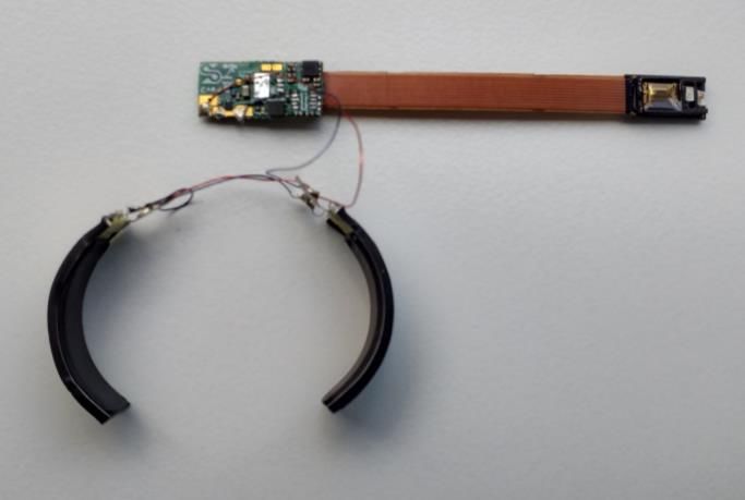
You can also read