Rubik's Cube Reconstruction from Single View for Service Robots
←
→
Page content transcription
If your browser does not render page correctly, please read the page content below
Rubik’s Cube Reconstruction from Single View for Service Robots
              Wlodzimierz Kasprzak, Wojciech Szynkiewicz, and Lukasz Czajka
                 Warsaw University of Technology, Institute of Control and Computation Eng.,
                                   ul. Nowowiejska 15/19, PL-00-665 Warsaw
                                        e-mail: W.Kasprzak@ia.pw.edu.pl

                                                    Abstract
      Rubik’s cube puzzle is considered to be a benchmark for service robots. In such an application a
      computer vision subsystem is required in order to locate the object in space and to determine the
      configuration of its color cells. In this paper a robust algorithm for Rubik cube reconstruction form a
      single view in real time is shown. Special interest was in getting a balance between quality of results
      and computational complexity of the algorithm.

Keywords: color analysis, shape description, segment grouping, service robots, surface orientation, 3-D
object recognition

1     Introduction
Quite recently the Rubik’s cube puzzle emerged as a benchmark for cooperating service robots [1], [2], [3].
Typical solutions require the use of a computer vision subsystem that processes images from one or more
cameras. Main goals of image processing in this context are: (1) an initial detection of the Cube object,
which leads the robot manipulator to move towards it; (2) the 3-D reconstruction of the Rubik’c cube
pose (localization, orientation), which allows the manipulator to grasp it; and finally (3) an appropriate
recognition of the color cells of all the 3 visible surfaces of the cube.
    The reconstruction of 3-D object in computer vision generally requires to extract image features in
several views, to find their correspondences and (approximately, in terms of the smallest total error)
to solve a system of equations [4]. An obvious observation is that the use of geometric constraints
can simplify the reconstruction problem, e.g. planarity, alignments, symmetries, known angles between
directions [5], [6]. As our object of interest, the Rubik cube, is of well-defined structure we can use a
single view and combine it with prior knowledge about this object. In this paper an algorithm for Rubik
cube reconstruction from a single view in nearly real time is shown. Special interest was to get a balance
between quality of results and computational complexity of the algorithm.
    Section 2 provides an introduction to the application domain, which is a service robot benchmark,
and it gives the overall solution structure. In section 3 the image analysis process is described: color
processing, cell detection, cell grouping and surface reconstruction.

2     The service robot benchmark
The development of service/personal robots functioning in a human-oriented environment is a major
scientific and technological challenge. One of the challenging problems for service robots is grasping and
manipulating objects in a semi-structured environment, where object properties are not known a priori
and sensing is prone to errors. Rubik’s cube puzzle solution is a task requiring nearly all skills that
are essential in a service robot. Thus, Rubik’s cube manipulation is an example of highly demanding
benchmark task for two-handed service robots, because it requires from the system:

    • a two-handed manipulation to efficiently turn the plates of the cube;
    • to have visual capabilities in order to locate the cube;
    • to have a visual servo-control to get hold of the cube;
    • a position-force control to avoid jamming of the cube while rotating the faces;

                                                        1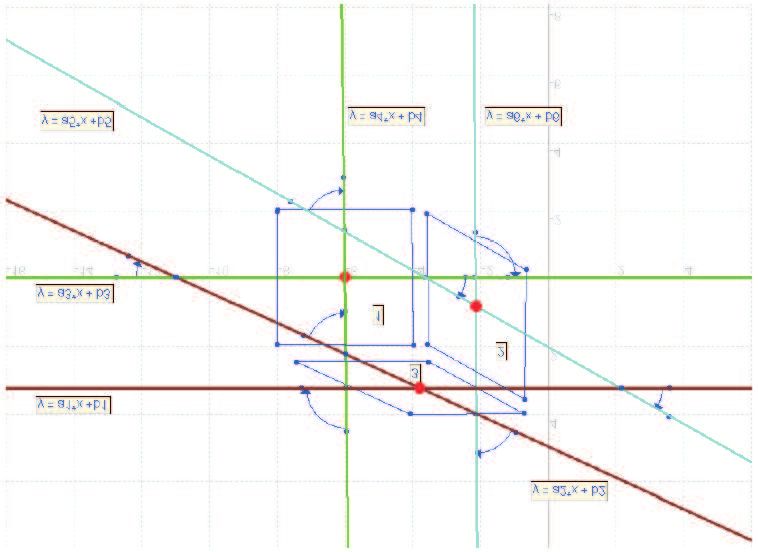
CCD camera
tactile sensor
force sensor
j
CMOS camera
IR sensor
Figure 1: Sensors used to locate and manipulate the Rubik’s cube.
• a fusion of deliberative and behavioral control to work out the plan of motions solving the puzzle
and to adapt quickly to sudden changes in the environment (e.g. in case of jamming).
Hence, a vision subsystem is responsible both for detecting and locating the cube in 3-D space, and
identifying its initial and current configuration, i.e. color cell configuration within the surfaces of the
cube.
The overall experimental setup consists of two 6 degree of freedom (dof) modified IRp-6 robot arms,
each with a parallel jaw gripper fig. 1. Each jaw is instrumented with tactile sensors which detect the
presence of contacts with the grasped object. Moreover, each hand is equipped with a wrist-mounted
ATI Gamma force-torque sensor, and an eye-in-hand miniature CCD color camera. Additionally, a
global vision system with fixed-mount SVS-Vistek SVS084 CCD color camera and Leonardo Digital
Video Processor from Arvoo for fast image acquisition and realtime processing of the incoming data is
used.
3 Rubik object reconstruction
The image analysis procedure allows the detection of Rubik’s cubes, based on a previous detection of
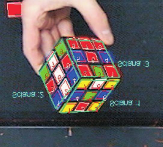
color cells and their grouping into up to 3 surfaces (Fig. 2).
Figure 2: The input image and the final segmentation image that contains cell groups (surfaces).
Color-based iconic processing
A proper color-based image processing requires that the white level in the input image is balanced, i.e.
that all levels of grey differ only by their intensity component Y, whereas their color components U and
V are centered. The input image is transformed from the RGB space into the YUV space. Then the
2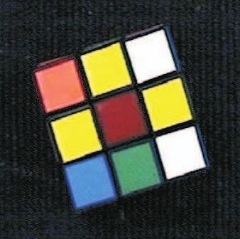
pixel color components are normalized with respect to pixel’s intensity (Fig. 3):
Yp0 = 128; Up0 = (Up − 128) · κp + 128; (1)
Vp0 = (Vp − 128) · κp + 128; (2)
where
Yp0
Yp for Yp > 128
κp = 256−Yp (3)
Yp0 for Yp < 128
1 for Yp = 128
Eventually an overflow can appear, i.e. Up0 , Vp0 > 255, but this is handled separately as overflow is
caused only by ”dark” or ”white” pixel. This normalization improves significantly the spiky-ness of the
histogram function - although the background pixels are still dominant in the histogram but now there
clearly appear also other local maximum peaks (Fig. 4).
Figure 3: The input image and the corresponding U- and V-images (after Y-based normalization).
Figure 4: The histograms of normalized U- and V-images.).
Next a pixel classification into hypothetic cell colors can be performed (Tab. 3). Besides the color
components Up0 and Vp0 of every pixel p a precondition for color detection is a sufficient (original) intensity
Yp - a very ”dark” or very ”white” pixel can not be Y-normalized and it contains no valuable color
information.
Cell recognition
The color-filtered image constitutes the input of cell detection (Fig. 5). The color image is post-processed
by a subsequent erosion- and dilatation-like filtering. This separates well the color regions one from each
other, while fully ”flooding” the internal homogeneous regions. Then a border tracking of homogeneous
regions is performed.
3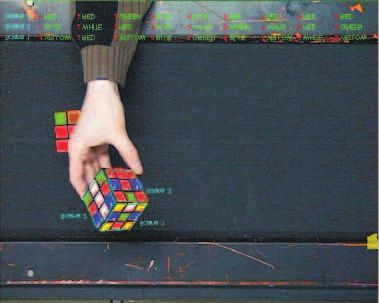
Table 1: The color component intervals for color detection.
                               Colorp       Yp         Up0          Vp0
                                         min-max      µ, 3σ       µ, 3σ
                                 red      50-140   110, ±38 205, ±45
                               orange    140-210   100, ±48 205, ±45
                                 blue     70-240   195, ±55 55, ±55
                                green     70-240    70, ±65      60, ±50
                                white    190-255   128, ±12 128, ±11
                                yellow   118-150    90, ±25 140, ±20

    The shapes of detected borders are characterized next. Several functions based on geometric moments
represent the invariant features of closed contours and by assigning appropriate constraints to them the
interested contours (corresponding to Rubik cells) can be detected. Among 10 tested moment-based
functions, the following four functions with corresponding conditions for square-like shapes were selected:
M 1 ≥ 1.0, M 2 ≤ 2.5, M 3 ≤ 0.5 and M 7 ≥ 0.1. These have been discovered to perform best for cell
contour detection:
                             M 1 = (µ20 + µ02 )/m200                                                    (4)
                             M 2 = (µ20 − µ02 )2 + 4µ211 /m400

                                                                                                        (5)
                             M 3 = (µ30 − 3µ12 )2 + (3µ21 − µ03 )2 /m500

                                                                                                        (6)
                             M7    =    (µ20 µ02 −   µ211 )/m400                                        (7)
where mpq , µpq are the global and central moments of order (p,q), with respect to the first and second
coordinate.
    For the contours that satisfy above conditions we finally checked their normalized compactness coef-
ficient γ:
                                                    L
                                               γ= √      −1                                          (8)
                                                  2 πS
which should be in the range of: γ ∈ [0, 0.4].

                    (a)                                (b)                          (c)

Figure 5: The steps of image segmentation in the ROI region: (a) after color-based filtering, (b) after
erosion, (c) after dilatation.

Cell configuration and surface detection
The surface detection step starts with the computation of 4 vertices for every contour - this leads to
2 main directions of every enclosed cell. The topological information (neighborhood) and the available
directions allow the grouping of cells into surfaces (Fig. 6). A more realistic case with 3 visible surfaces
is shown on Fig. 7.

3-D object reconstruction
The availability of camera calibration parameters is important for 3-D reconstruction - then the 2-D
point coordinates can be related to metric measurements. The Rubik cube reconstruction problem can

                                                        4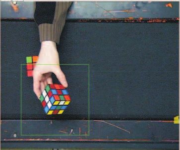
(a)
(b) (c) (d)
Figure 6: The steps of surface detection: (a) detection of 4 vertices, (b) cell border approximation (vertices
and border lines), (c) the topological structure (neighborhood) of cells, (d) the directional information,
based on vertex pairs, if 3 surfaces are visible.
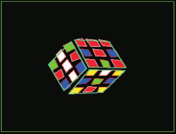
(a) (b) (c)
Figure 7: The Rubik object description if three surfaces are visible: (a) the topological information for 3
visible surfaces, (b) the detected surfaces, (c) the final Rubik object description.
be decomposed into cell configuration recognition and the estimation of the object-to-camera coordinate
system transformation. It is possible to detect the full cell configuration from a single view only then,
when 3 Rubik cube surfaces are visible. Otherwise, a fusion of information coming from all the 3 cameras
in the scene is needed. This is out of the scope of this paper.
The transformation of a scene point P onto an image point p can be expressed by a 4 × 4 matrix for
homogeneous coordinates:
kx a11 a12 a13 a14 X
ky . . . . · Y
p= kz = A · P = . (9)
. . . Z
k a41 a42 a43 a44 1
The third row is always linearly dependent on the fourth row of matrix A - we can consider three
equations corresponding to the 1-st , 2-nd and 4th rows. After elimination of the unknown coefficient k
from such a system of equations we have 2 potentially independent equations:
a11 X + a12 Y + a13 Z − a41 xX − a42 xY − a43 xZ − a44 x + a14 = 1 (10)
a21 X + a22 Y + a23 Z − a41 yX − a42 yY − a43 yZ − a44 y + a24 = 2 (11)
where i means the approximation error related to the i-th equation.
5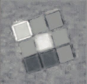
All the parameters aij of above matrix A depend on the following unknown parameters of the object-
to-camera coordinate transformation: the translation vector T = [tX , tY , tZ ], the rotation angle vector
Θ = [αZ , βX , γY ].
    With the knowledge of the focal length the depth of object’s origin point can be estimated from the
relation between known real size of the object and its projected image size. All the corner points of
the cube can be expressed in relation to this central point with help of the 6 unknown transformation
parameters. Even if only one surface is visible then we have 4 visible corners and thus a system of
8 equations can be defined. Hence all the unknown transformation parameters could be estimated.
Obviously these 4 points are coplanar and only one rotation coefficient can be estimated from them,
whereas the two remaining rotations are set to zero.

4     Tests
The implementation was tested on a computer with processor: P4 - 2400 MHz. The average surface
detection times were: -

    1. if the entire image is processed (initialization procedure):
       (a) one surface view - 90ms;
       (b) more than one surface is visible - 100 ms;
    2. processing a ROI part of the image only (after initialization):
       (a) one surface view : 32 ms;
       (b) more than a single surface view: 52 ms.

5     Summary
This works shows that a robust and fast reconstruction of the Rubik’s cube is possible from a single view
only. Thus by the use of a computer vision system we can support the benchmark task solution defined
for service robots - to solve the Rubik puzzle by two cooperating manipulators.

Acknowledgments
The research work reported in this paper was supported by a grant of the Polish Ministry of Scientific
Research and Information Technology - MNiI 4T11A 003 25.

References
 [1] R. Korf. Finding optimal solutions to rubik’s cube using pattern databases. In Proceedings of the
     National Conference on Artificial Intelligence (AAAI-97), July 1997, pages 700–705.
 [2] W. Szynkiewicz. Motion planning for multi-robot systems with closed kinematic chains. In Proceed-
     ings of the 9th IEEE International Conference on Methods and Models in Automation and Robotics
     MMAR’2003, Miedzyzdroje, pages 779–786, August 25-28 2003.
 [3] O. Tahri and F. Chaumette. Point-based and region-based image moment for visual servoing of
     planar objects. IEEE Transactions on Robotics, 21(6):1116–1127, Dec 2005.
 [4] O. Faugeras. Three-dimensional computer vision. A geometric viewpoint. The MIT Press. Cambridge,
     Mass. 1993.
 [5] P.F. Surm, S.J. Maybank. A method for interactive reconstruction of piecewise planar objects form
     single views. British Machine Vision Conference, BMVC 1999. BMVA Press 1999, pp. 265–274.
 [6] L. Venturino et al.. Improving 3D scene reconstruction through the application of geometric con-
     straints. In IWSSIP’04. Int. Workshop on Systems, Signals and Image Processing, Poznan University
     of Technology Press, September 2004, pp. 115-118.

                                                        6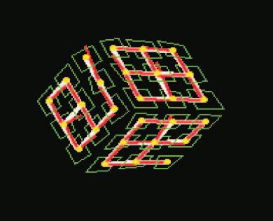
You can also read