Scalpel Owner's Manual Supplement - Cannondale
←
→
Page content transcription
If your browser does not render page correctly, please read the page content below
Scalpel
Owner’s Manual Supplement

READ THIS SUPPLEMENT AND YOUR
CANNONDALE BICYCLE OWNER’S MANUAL.
Both contain important safety information. Keep
both for future reference.
Scalpel - Owner’s Manual Supplement

                                             Safety Messages
                              In this supplement, particularly important information
                                         is presented in the following ways:

                                   Indicates a hazardous situation which, if
                                   not avoided, may result in death or serious
                                   injury.

                                   NOTICE
                                   Indicates special precautions that must be
                                   taken to avoid damage.

                                  The following symbols are used in this manual:

     Symbol          Name                                  Description
        NG
            LI
               -2    NGLI-2 synthetic grease               Apply NGLI-2 synthetic grease.

       CR
         B-
              GE
                 L   Carbon gel                            Apply carbon gel (friction paste) KF115/

                     Medium-strength
            2                                              Loctite® 242, Loctite® 243
                     removable thread lock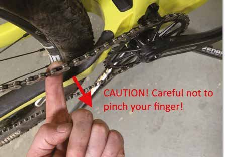
English

 Cannondale Supplements                                            CONTENTS
 This manual is a “supplement” to your
 Cannondale Bicycle Owner’s Manual.                    Safety Information.....................2-6
 This supplement provides additional and               Technical Information..............7-29
 important model specific safety, maintenance,
 and technical information. It may be one of           Replacement Parts...................... 30
 several important manuals/supplements for
 your bike; obtain and read all of them.               Maintenance................................ 32
 Please contact your Authorized Cannondale
 Dealer immediately if you need a manual
 or supplement, or have a question about
 your bike. You may also contact us using
 the appropriate country/region/location
 information.
 You can download Adobe Acrobat PDF
 versions of any manual/supplement from our
 website: http://www.cannondale.com.

                                                       Your Cannondale Dealer
 Contacting Cannondale                                 To make sure your bike is serviced and
                                                       maintained correctly, and that you protect
 Cannondale USA
                                                       applicable warranties, please coordinate
 Cycling Sports Group, Inc.                            all service and maintenance through your
 1 Cannondale Way,                                     Authorized Cannondale Dealer.
 Wilton CT, 06897, USA
 1-800-726-BIKE (2453)
                                                        NOTICE
                                                        Unauthorized service, maintenance, or
 Cycling Sports Group Europe B.V                        repair parts can result in serious damage
                                                        and void your warranty.
 Mail: Postbus 5100
 Visits: Hanzepoort 27
 7570 GC, OLDENZAAL, Netherlands
 Tel: +41 61 551 14 80
 Fax:+31 54 151 42 40

 International Distributors
 Consult our website to identify the appropriate
 Cannondale Dealer for your region.

137384                                             1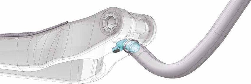
Scalpel - Owner’s Manual Supplement

                             SAFETY INFORMATION

 Important Composites                               Inspection & Crash Damage
 Message                                            Of Carbon Frames/Forks

                                                    After A Crash Or Impact:
  Your bike (frame and components) is made
  from composite materials also known as            Inspect frame carefully for damage. See
  “carbon fiber.”                                   PART II, Section D. Inspect For Safety in
                                                    your Cannondale Bicycle Owner’s Manual.
  All riders must understand a fundamental
  reality of composites. Composite materials        Do not ride your bike if you see any sign
  constructed of carbon fibers are strong           of damage, such as broken, splintered, or
  and light, but when crashed or overloaded,        delaminated carbon fiber.
  carbon fibers do not bend, they break.
                                                    Any of the following may indicate a
  For your safety, as you own and use the           delamination or damage:
  bike, you must follow proper service,
                                                    •    An unusual or strange feel to the
  maintenance, and inspection of all the
                                                         frame
  composites (frame, stem, fork, handlebar,
  seat post, etc.) Ask your Cannondale              •    Carbon which has a soft feel or
  Dealer for help.                                       altered shape
  We urge you to read PART II, Section D.           •    ·Creaking or other unexplained noises,
  “Inspect For Safety” in your Cannondale
  Bicycle Owner’s Manual BEFORE you ride.           •    Visible cracks, a white or milky color
                                                         present in carbon fiber section
  You can be severely injured, paralyzed
  or killed in an accident if you ignore this       Continuing to ride a damaged frame
  warning.                                          increases the chances of frame failure,
                                                    with the possibility of injury or death of
                                                    the rider.

137384                                          2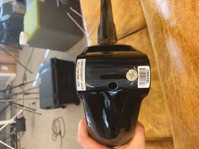
English

 Intended Use                                        Tightening Torques
                                                     Correct tightening torque for the fasteners
                    The intended use of              (bolts, screws, nuts) on your bicycle is very
                    all models is ASTM               important to your safety. Correct tightening
                    CONDITION 3,                     torque for the fasteners is also important for
                    Cross-Country.                   the durability and performance of your bicycle.
                                                     We urge you to have your dealer correctly
                                                     torque all fasteners using a torque wrench. If
                                                     you decide to torque fasteners yourself always
                                                     use a torque wrench.
                                                     Find Tightening Torque Information:
  Please read your Cannondale Bicycle
  Owner’s Manual for more information about           The wide range of bicycle models and
  Intended Use and Conditions 1-5.                    components used means that a listing of
                                                      tightening torque would be out of date by
                                                      the time it was published. Many fasteners
                                                      should be installed with a thread locking
                                                      adhesive such as Loctite®.
                                                      To determine correct tightening torque
                                                      and any adhesive application for a
                                                      fastener we ask you to check:
                                                      •    Many components are marked.
                                                           On-product marking is becoming
                                                           common.
 Servicing
                                                      •    ·Torque specs in the component
                                                           manufacturers instructions shipped
                                                           with your bicycle.

  This supplement may include procedures              •    Torque specs listed on the websites of
  beyond the scope of general mechanical                   component manufacturers.
  aptitude.
                                                      •    With your dealer. Dealers have access
  Special tools, skills, and knowledge may                 to current data and have experience
  be required. Improper mechanical work                    with correct torque for most
  increases the risk of an accident. Any                   fasteners.
  bicycle accident has risk of serious injury,
  paralysis or death.
  To minimize risk we strongly recommend
  that owners always have mechanical
  work done by an Authorized Cannondale
  Dealer.

137384                                           3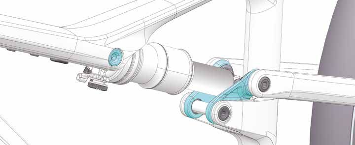
Scalpel - Owner’s Manual Supplement

 Maximum Fork Length
 Maximum Fork Length is an important frame safety testing specification for front suspension
 mountain bikes. You must observe the measurement when installing headset parts, headset
 adapters, installing and adjusting a fork, and selecting replacement forks.

                                              From
                                         Bottom Of Frame
                                            Head Tube

                                                      Maximum
                                                      Fork
                                                      Length

                                                            To Center Of
                                                            The Fork Axle

   You must select a replacement fork not only based on head tube diameter but the critical
   factor of frame maximum fork length.
   Do not exceed maximum fork length. Exceeding the MAXIMUM FORK LENGTH limit can
   overload the frame causing it to break while riding. Your retailer MUST follow and observe
   this specification for your bike.
   You can be severely injured, paralyzed or killed in an accident if you ignore this warning.

137384                                           4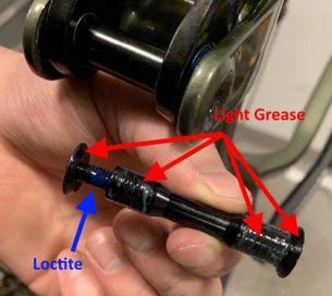
English

 Rear Shocks                                         Minimum Seat Post Insert

  Select only compatible shocks and forks            Make sure at least 100 mm of the seat
  for your bike. Do not modify your bike in          post is inserted into the frame at all
  any way to mount one.                              times.
  Have your shock or fork installed by a             Failure to insert the seat post at least 100
  professional bike mechanic                         mm can place a very high stress on the
                                                     seat tube top tube junction causing the
  Riding with the wrong rear shock can               frame to fail while riding.
  damage the frame. You could have a
  serious accident. Make sure the total              Remove the seat post. Measure 100 mm
  travel, eye-to-eye length, and stroke length       from the bottom of the seat post. Use a
  of the rear shock you select meet the              permanent marker to mark the post at 100
  “Specifications” listed in this manual.            mm.
  When selecting different shocks or forks           When adjusting the seat post height in
  for your bike, make sure that the shock            the seat tube, never adjust the seat post
  or fork you select is compatible with your         so that the line you mark is above the top
  bike’s design and how you will use your            edge of the seat tube.
  bike.
                                                     You must also be aware that bicycle seat
  You can be severely injured, paralyzed             posts are permanently marked by the
  or killed in an accident if you ignore this        manufacturer with a “minimum insert”
  warning.                                           line on the seat post itself. You must not
                                                     rely on this marking as an indication of the
                                                     proper minimum seat post insertion depth.
                                                     You can be severely injured, paralyzed
                                                     or killed in an accident if you ignore this
                                                     warning.

137384                                           5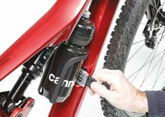
Scalpel - Owner’s Manual Supplement

 Tire Size x Maximum Width

  Observe the Tire Size x Maximum Width for your bike found in the “Specifications” page of
  this manual.
  Mounting the wrong size tires can result in the tires hitting the fork or frame when riding. If
  this happens, you can lose control of your bike and you can be thrown off, a moving tire can be
  stopped because it touches the fork or frame.
  Do not mount oversized tires, ones that rub or hit the fork or frame, ones that result in too little
  clearance, or ones that can hit the fork or frame, saddles, seat post, or seat post clamps seat post
  when the suspension is fully compressed or when riding.
  Take care that the tires you select are compatible with your bike’s fork or frame design. Also, be
  sure to follow the manufacturer’s recommendations of your front fork and rear shocks.
  When you are considering tires for your bike consider...
  The actual measured size of a tire may be different than its sidewall marking. Each time you
  mount a new tire, take the time to inspect the actual clearance between the rotating tire and all
  parts of the frame. The U.S. Consumer Product Safety Commission (CPSC) requires at least 1/16”
  (1.6 mm) tire clearance from any part of the bike. Allowing for lateral rim flex and a wheel or rim
  that is out-of-true will likely mean choosing a rear tire that provides even more clearance than the
  CPSC recommends.
  Ask your authorized brand retailer for the right tires for your bike and its particular
  components! You can be severely injured, paralyzed or killed in an accident if you ignore this
  warning.

 Serial Number                                                                               2

 The serial number is located on the bottom
 bracket. It is a 7-character barcode (1). Use
 this serial number to register your bike.

     To register your bike: go to the
     Product Registration section of our
     website at www.cannondale.com

                                                               1

                                                         1. Serial Number
                                                         2. Product Codes

137384                                            6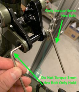
English

                         TECHNICAL INFORMATION
 Specifications

  Item                                                  Specification
  Rear Travel                                           100 mm, SE: 120 mm
  Head Tube                                             UPR: 1-1/8”, LWR: 1-1/2”
  Headset                                               FSA Orbit C-40-ACB No. 42
  Bottom Bracket: Type/ Width                           PF30 / 83 mm
  Front Derailleur                                      N/A
  Seat Post: Dia./Binder                                31.6 mm / 34.9 mm
     Min. Seat Post Insert                              100 mm
     Tire Size x Max. Width                             622 x 61 mm
     Max. Fork Length                                   532 mm
                                                        190 mm / 40 mm /FT: M8 x 25 mm, RR: None
  Rear Shock: Eye-To-Eye / Stroke / Bushing
  Width                                                 SE: 190 mm / 45 mm / FT: M8 x 25 mm ,
                                                        RR: None
                                                        25%, 10 mm
  Sag
                                                        SE: 25%, 11 mm
  Chain Guide                                           Integrated w/ Main Pivot
  Rear Brake: Mount Type /
                                                        Post Mount / 160 mm / 180 mm
  Min/Max Rotor Dia
                                                        148x12 Speed Release TA M12 x 1.0p x 176 mm
  Rear Axle: Type/Length
                                                        Overall Length
                                                        Rear Wheel: 3 mm Boost Ai Offset to NDS
  Ai Offset:                                            Hollowgram SpideRing: Ai Offset
                                                        SRAM Chainring: +6 mm Offset
                                                        ASTM Condition 3, Cross Country, Marathon,
     Intended Use
                                                        Hardtails
     Max. Weight Limit
                                                        305 lbs. / 138 kg.
  Total (rider+all equipment):

 All Specifications subject to change without notice.

137384                                          7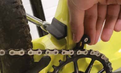
Scalpel - Owner’s Manual Supplement

 Geometry                                                           B

                                                                C
                                                                            P                        G

                                   E
                                                                                                                       O

                                                     75 mm

                                       E’                       F

                                                                                            D
                      A

                                            J                                         I
                                                        L               K                                        M

                                                                                                                      N
                                                            H

                                                                        SCALPEL                                  SCALPEL SE
         Size                                       S                   M             L         XL        S           M           L      XL
         Wheel Size (in)                                                        29                                          29
A        Seat Tube Length (cm)                      43               44               48     52          43           44          48     52
B        Top Tube Horizontal (cm)                  56.7             59.9             62.2   64.4         58          60.2        62.5   64.8
C        Top Tube Actual (cm)                      53.1             55.3             57.7   60.3         53.1        55.3        57.7   60.3
D        Head Tube Angle                                                   68                                               67
E        Seat Tube Angle Effective                                        74.5                                             75.5
E’       Seat Tube Angle Actual                    68.8             69.3       69.6           70         67.8        68.3       68.7     69.1
F        Standover (cm)                            74.3             73.9         74         73.7         75.5        75.6       75.8    76.0
G        Head Tube Length (cm)                      9.5             10.5        11.5         12.5         9.5        10.5        11.5    12.5
H        Wheelbase (cm)                            112.8            115.1      117.5        119.9        112.5       114.8      117.2   119.6
I        Front Center (cm)                         69.5             71.8       74.2         76.6          69          71.4      73.8    76.2
J        Chain Stay Length (cm)                                           43.6                                             43.6
K        Bottom Bracket Drop (cm)                                           4                                               3.2
L        Bottom Bracket Height (cm)                                       33.1                                             34.4
M        Fork Rake (cm)                                                    5.5                                              4.4
N        Trail (cm)                                                         9                                              11.2
O        Stack (cm)                                58.2             59.1       60.1          61          59.2        60.2        61.1   62.1
P        Reach (cm)                                41.5             43.5       45.5         47.5         40.4        42.4       44.4    46.4
         Head Tube Height (cm)                     51.2             51.2       51.2         51.2         53.2        53.2       53.2    53.2
         Rear Travel (cm)                                                  10                                               12
         Shock Eye-to-Eye (mm)                                             19                                               19
         Rear Stroke (mm)                                                  40                                               45
         Recommended Sag 25% (mm)                                          10                                                11

Specifications subject to change without notice.

137384                                                          8
English
Bottom Bracket - PF30 / 83 mm MTB
6
1
5
4
3
Loctite 680 (green)
7 1
Clean surface and apply Loctite® 680 retaining compound, ensure that
both mating surfaces of the cup are completely covered before pressing in
the PF30 cups. Allow time to cure according to Loctite instruction prior to
proceeding with bearing installation. below:
Identification
1. Frame BB Shell 6. Cable Sheath and Dropper Zip
2. Cable Funnel Tie Mount
3. Cable Sheath 7. Bearing Cup
4. Dropper Foam
5. Internal Dropper cable guide
NOTICE
To avoid serious damage to the frame, follow the manufacturer’s instruction for assembly and
installation of the bearing system. Use the specified bottom bracket tools when servicing. Consult
with your Cannondale Dealer on the quality and compatibilty of any proposed replacement
component. Do not use chemical solvents to clean. Do not remove frame material or use surfacing
tools on bottom bracket shell. Frame damage, caused by improper components, component
installation or removal is not covered by your warranty.
137384 9Scalpel - Owner’s Manual Supplement
Main Pivot
grea
se
grea
1
15-20 N·m se
Torque this side. Loctite™ 243
Hold this side.
2
3
Loctite™ 243
Identification
1. Main Pivot Axle
2. Pivot Bolt No grease
3. Cable Guide
Lightly apply grease to outside surfaces of the main pivot axle (1).
Insert the main pivot axle into non-drive side.
Apply Loctite 243 to either the pivot bolt (2) or the chain guide (3) threads. Do not use
grease on the chainguide. Grease could result in unwanted rotation of this part.
Important: Hold the pivot bolt and tighten main pivot axle to the specified torque.
137384 10English
Swingarm Cable Funnel
3
1
7
8
3
9
4
2
Identification
2-3 N·m
1. Swingarm
2. Cable Funnel 6
3. Spacer (10X6 mm)
4. Dropper Foam 5
5. Tie
6. Bolt Item (3), installed before the cable funnel (2)
7. Rear Derailluer
8. Rear Brake is installed prevents chain funnel rotation
9. rivnut while cable are installed. Center this part on
the swingarm in front of the rivnut (9).
137384 11Scalpel - Owner’s Manual Supplement
Seat Tube Fender
1
2
Identification
1. Seat Tube
2. Fender
The fender (2) shields the frame opening
from intrusion and accumulation of dirt,
debris and water thrown by a rotating tire.
The fender has adhesive tape on the seat
tube (1) facing surface.
If the fender is damaged, the fender should
be removed by carefully lifting the fender
progressively around it entire edge from the
frame with a plastic or other non-marring
tool to prevent damage to the frame finish.
Before applying a new fender, clean the
frame and wipe the area behind the fender
with isoproyl alcohol and allow it to dry.
NOTICE
Center the new fender on the opening and Check and replaced if necessary as part of
align the bottom edge with the opening. Pre-Ride and Routine maintenance checks. See
“Replacement Parts.”
137384 12English
Seat Stay / Chain Stay Protectors
This inside surface is a
chain controlling surface.
Incidental chain contact can
result in normal wear leading
to paint chipping or light
scratches.
4
1
3
2
Seat Stay Protectors (1 & 4) - Place close to
dropoput on center of tube.
Right Chainstay Protector (2) - Position so
curve of the protector follows the frame.
Protector wraps along and over the chainstay
edge as shown. If the protector is position
too far back, the chain may chip the paint
finish.
Both Chainstay Protectors (2 & 3) - Make
sure the rearward edge of the protectors are
parallel with edge of the dropout.
137384 13Scalpel - Owner’s Manual Supplement
Downtube Protectors
Upper Protector (1) 1
Place in middle of bend
in center of tube. Item
not used on size SM.
2
Lower Protector (2)
Center relief cuts over tube
bend as shown. Position
forward from BB shell hole
as shown.
Appx. 40 mm
137384 14English
Cable Routing c. There is a cable tie guide located on
the back wall of the “garage” inside of
The Scalpel has tube in tube routing in the the front triangle. Cable tie the dropper
rear triangle, which feeds into a rubber hose cable to this guide. This makes sure the
that is inside the downtube of the front cable does not rub on the front of the
triangle. chainstay during suspension movement.
Steps for installation:
1. Both the fork and the swingarm should
be disconnected from the main frame to
allow cable routing access.
2. Install the dropper post according to the
manufacturer‘s recommendation.
a. Route the cable for the dropper post
from the seat tube into the downtube.
Ensure that the cable routes over the
bottom bracket rather than around it.
b. Route the portion of the dropper cable
inside the downtube within the 9mm I.D.
foam tube, similar to what is seen in the
image below. CBRT-2
d. TIP: run this cable guide slightly loose
so that the cable can slide through it for
dropper post height adjustments.
3. Install the “cable funnel” onto the
bottom of the chainstay.
CBRT-1
137384 15Scalpel - Owner’s Manual Supplement
a. Tighten the cable funnel into place with d. Side Notes:
the funnel shifted all the way forward in
its adjustment slot.
b. Attach the rubber hose to the cable
funnel with a 5mm wide cable tie. Use
the cable tie to cinch the rubber tube
down onto the cable funnel. Slightly tug
on the rubber hose to make sure it is
secured to the funnel.
c. Side Notes:
i. The Cable Funnel Tubing and Tie is
un-shurnk shrink wrap tubing with a 16 x
650 mm diameter. If stock is unavailab-
le, you can use also use a light-weht road
bike tube cut and sized to fit.
CBRT-4
5. When the main pivot is installed, make
sure the cable funnel does not make
contact with the front triangle.
a. Check to make sure that the water bottle
fixing bolt does not contact the rear
triangle. (CBRT-5) The water bottle fixing
bolt is a button head M5 x 0.8 x 20mm.
CBRT-3
4. Keeping the rear triangle off the bike,
install both the shift housing and brake
hose, Install both the shift housing and
brake line into the tube in tube cable
ports on the inside of the chainstays.
a. Ensure the cable routes into the cable
funnel and rubber.
CBRT-5
b. Once the cables have traveled most of
the way through the rubber hose, install
the rear triangle onto the front triangle
6. Once the main pivot is installed, route
and assemble the main pivot.
137384 16English
the shift cable housing and brake line into
the desired head tube cable port, allowing
the cable to exit the frame.
a. Make sure the cables will not come into
contact with the fork steerer tube. Photo
taken at inside headtube showing cable
entrance, avoiding steerer tube.
CBRT-7c
CBRT-6
7. The final step is to secure all of the cables
in the downtube to the cable guide on the
bottom of the tool holder.
a. This is secure the cables within the frame
and prevent cable rattle.
b. Unbolt and remove the tool holder on the
down tube, exposing the hole underneath. CBRT-7c
c. Thread a zip tie around the dropper cable
and rubber hose (which contains the shift
and brake housing) in the downtube.
137384 17Scalpel - Owner’s Manual Supplement
e. Thread the cable tie through the cable guide
on the bottom of the tool storage piece.
CBRT-7f
CBRT-7e
g. The cable sleeve and foam tube should be
checked for wear at least once per season.
If significant wear is seen, replace the
affected components.
CBRT-7e2
f. Tighten the zip tie, holding the end of the zip
tie off to one side of the frame. Tighten the
zip tie until it is snug around the cables and
hose. Clip the end of the zip tie and proceed
the install the tool holder to the frame.
137384 18English
Chain Guide Setup c. Torque the main pivot to 15Nm.
1. To set up the chain guide:
a. Shift into the largest cog on the
cassette.
CNG-3
2. Hold the chain guide in place while
torquing.
CNG-1
d. The lower surface of the chain guide
should be 3mm above the chain.
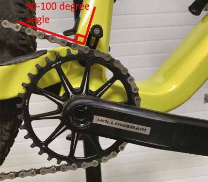
b. Align the chain guide so that it is
perpendicular (90 degrees) to the chain. Place a 3mm allen key flat on top of the
chain and lower the chain guide into the
allen key, then torque to spec.
CNG-2
CNG-4
137384 19Scalpel - Owner’s Manual Supplement
e. Confirm the chain guide is operating
properly by pulling the chain towards the
outside of the bike, attempting to derail
the chain, while pedaling it forward (by
hand) in the work stand. The chain should
not come off of the guide. If the chain
does come off of the guide, slightly lower
the guide until it does not.
Large Chainring Small Chainring
CNG-5
Chain guide rotation
When removing the main pivot or if the chain
guide rotates while riding:
CNG-5
1. Remove the main pivot bolt, clean the
threads and reapply Loctite 243 thread-
locker.
f. Confirm the chain guide does not rub
while the rider is pedaling the bike in the
largest cassette cog, with the correct sag
2. Reassemble the main pivot bolt and
at the shock (sag at the shock is 10mm).
chainguide and torque to 15-20 N-m
If the guide rubs on the chain when sag
is set, the angle of the back plate can be 3. Allow the threadlocker to dry according to
rotated forward another 5 to 10 degrees. manufacturer‘s recommended time.“
You are able to rotate the angle of the
back plate forwards another 5 to 10
degrees.
Keep fingers away from chain ring.
137384 20English
Rear Shock
SAG
Shock Eye-to-Eye (mm) 190 mm
SCALPEL: 40 mm
Rear Stroke SCAPEL SE: 45 mm
SCALPEL: 25%, 10 mm
Recommended Sag SCAPEL SE: SE: 25%, 11 mm
Setting Sag
1. Set the air pressure according to for you body weight. Follow the shock manufacturer’s instruction
for pressurizing the shock.
2. Slide the O-ring against the shock wiper seal.
3. Sit on the bike in a normal riding position with your hands on the handlebar and feet on the pedals
so that your weight compresses the rear shock.
4. Measure the SAG. Adjust the air pressure in the shock to achieve the correct SAG measurement.
Add air to decrease sag.
Release air to increase sag.
137384 21Scalpel - Owner’s Manual Supplement
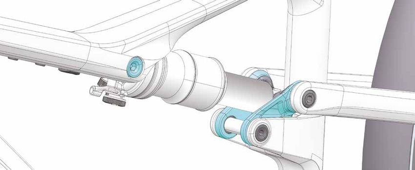
Shock Link
NOTICE
Mount shocks in orientation shown: controls forward and facing down as shown.
Front Shock Bolt (14) & Small Washer (15) - Ensure the small washer (15) is used. Ensure the front
shock bolt inserts through the shock eyelet when you insert the bolt.
Link Shock Pin (4) - The link is designed for use with shocks with DU bushings. The bolted shock
pin is specified for use with both Rockshox and Fox shocks utilizing DU bushings.
If the pin is removed from the rear shock, a new DU bushing must also be installed in the eyelet
to prevent play. DU bushings are wear items. Expect to replace them regularly. DO NOT APPLY
GREASE ON THE CENTER OF PIN. ONLY GREASE PIN ENDS WHEN FIXING TO LINK.
Eyelet Centering Spacers (6) - Make sure to place the two 1.6mm thick shock spacers on both
sides of the shock eyelet. This centers the eyelet and prevents wander and uneven wear of the DU
bushing.
Shock Pin Bolt Covers (7 & 8) - Keep the shock pin bolt link covers in place to prevent corrosion that
may result from water collecting in the bolt heads.
To Install the Covers:
1. Loosen the seatstay link bolt.
2. Place the covers on on the link.
3. Hold the covers in place while tighten-
ing the seatstay link bolt to the specified
torque.
Please Note: Pressing the covers into place
without following the outlined steps can cause
the rubber to deform, making the covers dif-
ficult to reinstall later.”
137384 22English
1
1 3
1
2
14
2
15
15 N·m
7 8
6 5 2
7 N·m
4
grease
6
2
5 N·m
9
2
9 9
5 N·m
10
12 11
Identification
1. Rear Shock 6. Eyelet Centering Spacers 11. Spacer
2. Rear Shock Adjusters 7. Left Cap Cover 12. Bearing Spacer
3. Shock Link Assy 8. Right Cap Cover 13. Pivot Axle Bolt
4. Link Shock Pin 9. Seat Stay Pivot Bolt 14. Front Shock Bolt
5. Pin Bolts w/washers 10 Frame Pivot Axle 15. Small Washer (0.5mm thick)
137384 23Scalpel - Owner’s Manual Supplement
Asymmetric Integration - Ai
NON-DRIVE DRIVE
3mm
148mm
The Ai rear hub is offset 3 mm to the drive side. This both aligns the cassette with the Ai frame’s 55mm
chain line, and aligns the rim/tire with frame’s center line for correct tire clearance.
Ai wheels have equal spoke angles and tension on both sides (non-dished wheel) which improves wheel
stiffness, strength.
• The 3 mm offset is for 148 X 12 mm spacing only!
• Other Ai equipped bike with 142 mm or 135 mm rear spacing use a 6 mm offset.
NOTICE
USE ONLY 3 mm “Ai” OFFSET REAR WHEELS. Incorrect wheel offset can damage your frame.
Standard wheel assembled on this frame will result in insufficient tire clearance leading to rubbing and
serious frame damage. This kind of damage is not covered by the Cannondale Limited Warranty.
Building/Truing a Wheel
If you chose to build, or true the wheel, make sure the 3 mm offset is present. Consult with your
Cannondale Dealer if you have any questions.
137384 24English
Hanger Replacement
2
2
2 N·m
1
grease
• Before installing a new hanger, be sure to clean any dirt or debris on the dropout with a nylon
brush (old toothbrush).
• Inspect the area for any damage.
• Lightly grease the dropout surface.
• Always clean and re-apply the specified thread lock to the bolt threads.
• Tighten with a torque wrench to the specified torque.
137384 25Scalpel - Owner’s Manual Supplement
Down Tube - Cover/Tool Carrier
The downtube of the Scalpel supports the use of a tool carrier (3) developed specifically for the frame.
The tool carrier is an optional item. A water bottle cage can be mounted above the carrier. The tool
carrier contains a specific multi-tool (4), a tire repair plug tool (5), and a mounting for a C02 tire inflation
device (6). The carrier position on the down tube can be adjusted. Notice the ovalized mounting holes.
See Replacement Parts for ordering information.
A blank cover (2) is in place when the optional tool carrier is not present. Do not ride the bike without
either the cover or the tool carrier securely attached to the downtube.
Both the cover and tool carrier also function to secure internally routed cables. A small cable guide is
attached to the underside of both. Setup for this guide is explained in the Cable Routing section of this
manual.
To install the multi-tool:
1. Slide out the tool tray (a) until it stops.
2. Insert the multi-tool (4) onto the tray behind the tray lip (b).
3. Slide the tray and tool back into the tool body until the latch (e) (located on the underside of the
sliding tray), clicks or latches into the tool body. You can feel the click when latched.
Confirm that the tray is latched by lightly pulling the tray. the tray, when latches should not slide
out easily.
NOTICE
Make sure the tool tray is always latched. If the tray is not latched correctly, the tool will not be
captured securely and may be lost during a ride.
Identification
1. Down Tube
2. Cover
3. Tool Carrier
a
4. Multi-Tool (Fabric)
5. Dyna Plug Tire Repair Tool
6. CO2
7. Retaining Screws
8. CO2 Strap
a. Tool Tray
b. Tray Lip
c. Tire Tool Clip
d. Strap Tensioning
e. Tray Latch
f. Cable guide
e
f
137384 26English
6
2 3
7
1.5 N·m
No Loctite
grease
1 5
b 4
a
tc h”
“La
8
5
c
d
137384 27Scalpel - Owner’s Manual Supplement
REPLACEMENT PARTS
L
B
2X R
2
8 N·m 7 N·m
2X K
W
2X grease
F 2
A 2 5 N·m
M
5 N·m
2X
Q
Q
2X
E
M12x1.0P 2X
R
E 2X
2
2-3 N·
Notes: C
1. Internal cable routing should start from rear of frame
2. Rear triangle uses tube in tube construction
Notes:3. As needed, replace all bearings in assemblies as full compliment bearings (do not re-use) D O
4. Lightly grease all bearing before press fit
1. Internal cable routing should start from rear of frame
5. Lightly grease under all counter-sink bolt heads 2-3 N·m
2. Rear triangle
6. First assembleduses tube
with bolts usingin tube construction
pre-applied NYLOK blue patch.
3. AsAfter
needed, replace
removal, check all bearings
patch material. inclean
If necessary, assemblies asthreads
off residue, clean full compliment bearings (do not re-use)
4. Lightly grease
and re- apply all bearing
medium-strength threadbefore
locker (e.g.press
Loctite™fit
242 (blue).
Apply 180
5. Lightly degrees ofunder
grease bolt diameter.
all counter-sink bolt heads
6. First assembled with bolts using pre-applied NYLOK blue patch. After removal, check
patch material. If necessary, clean off residue, clean threads and re- apply medium-strength
thread locker (e.g. Loctite™ 242 or 243 (blue). Apply 180 degrees of bolt diameter.
ID Part Number Description
A K33001 Derailleur Hanger TA ST SS 078
B K83061 Speed Release TA 148x12 176 mm M12x1.0P
C K32011 Cable Funnel Tubing and Tie
D K32001 Cable Funnel w/ Bolt
E K34001 CS Flex Covers NDS and DS
F K34021 SS Inboard Frame Protector
G K34031 HT Rub Guard Clear Protectors
H K32021 DT Blank Cable Guide
I K32031 DT Tool Cable Guide w/ CO2 Retainers
J K91001 Scalpel Shock Bolt Upper
K K91011 Scalpel Shock Reducer Lower
L K34011 Scalpel Link Covers Right and Left
137384 28English
J
V 2
15 N·m
2 S
G
N·m
2
5 N·m
Optional
I
Q 1.5 N·m
No Loctite or S
H
N
2
P Q 15-20 N·m
Torque this side only.
????
Not on size SM
2
2-3 N·m
O
U
Q
T
For use with dropper post
spec frames only.
Tubing length 650 mm
ID Part Number Description
M K91021 Scalpel Suspension Link 29 /w brgs
N K11001 Scalpel Rear Fender
O K11011 Scalpel Chainguide Complete
P K11021 Scalpel Chainguide Top
Q K91031 Scalpel Pivot Hardware
R K91041 Scalpel Pivot CS SS Link Bearings
S K32041 Scalpel Frame Grommets
T K32051 Scalpel Dropper Tubing
U K34051 DT Frame Protector
V K91081 Scalpel Shock Bolt Washer
W K36041 Scalpel Shock Pin Spacers Qty 2
137384 29Scalpel - Owner’s Manual Supplement
MAINTENANCE
The following table lists only supplemental maintenance items.
Please consult your Cannondale Bicycle Owner’s Manual for more information on basic bike
maintenance.
Item Frequency
Cable Routing - Make sure control cables are in place,
undamaged and attached securely. Before first ride
Frame Protection - Check the various frame protectors
(downtube, headtube, chainstay, swingarm on your bike. Make
sure they are in place and in good condition.
Damage Inspection - Clean and visually inspect entire bike
Before and after each ride
frame/swing arm/linkage assembly for cracks or damage.
Check Tightening Torques - In addition to other component
specific tightening torques for your bike. tighten according to the Every few rides
“Tightening Torques” information listed in this supplement.
Disassemble, clean, inspect, re-grease, replace worn or damaged In wet, muddy, sandy
parts in the following assemblies: conditions every 25 hrs.
In dry, conditions
• Shock Link • Pivot Axles • Frame Pivot Bearings
every 50 hrs.
Fork and Shock- Consult the manufacturer’s owner’s manual for maintenance requirements.
Any part of a poorly maintained bike can break or malfunction leading to an accident where
you can be killed, severely injured or paralyzed.
Frequent checks are necessary to identify the problems that can lead to an accident.
See “Inspect For Safety” in your Cannondale Bicycle Owners Manual.
137384 30English
WWW.CANNONDALE.COM
© 2020 Cycling Sports Group
Scalpel Owner’s Manual Supplement
137384

 CANNONDALE USA               CANNONDALE EUROPE                   CANNONDALE UK
 Cycling Sports Group, Inc.   Cycling Sports Group Europe, B.V.   Cycling Sports Group
 1 Cannondale Way,            Hanzepoort 27, 7575 DB, Oldenzaal   Vantage Way, The Fulcrum,
 Wilton CT, 06897, USA        contact@cyclingsportsgroup.com      Poole, Dorset, BH12 4NU
 1-800-726-BIKE (2453)                                            +44 (0)1202732288
 www.cannondale.com                                               sales@cyclingsportsgroup.co.uk
You can also read