Sediment Deposition and Contamination Potential from Treated CSO Discharges - Technical Memorandum 750
←
→
Page content transcription
If your browser does not render page correctly, please read the page content below
Technical Memorandum 750

Sediment Deposition and Contamination
Potential from Treated CSO Discharges

                  January 2012

           King Street Center, KSC-NR-0512
               201 South Jackson Street
                  Seattle, WA 98104
For comments or questions, contact: Karen Huber King County Wastewater Treatment Division 201 S. Jackson St. KSC-NR-0512 Seattle, WA 98104-3855 206-684-1246 Karen.Huber@kingcounty.gov Alternative Formats Available 206-684-1280 TTY Relay: 711
Contents

1    Executive Summary ............................................................................................................... 1
     1.1 Background and History ............................................................................................... 1
     1.2 Purpose .......................................................................................................................... 1
     1.3 Approach ....................................................................................................................... 1
     1.4 Results ........................................................................................................................... 2
2    Introduction ............................................................................................................................ 3
     2.1 Background and History ............................................................................................... 3
     2.2 Purpose .......................................................................................................................... 3
     2.3 Approach ....................................................................................................................... 3
     2.4 Modeling Workflow...................................................................................................... 6
     2.5 WA Sediment Quality Standards .................................................................................. 7
3    Model Input Data ................................................................................................................... 9
     3.1 CSO Characterization ................................................................................................... 9
     3.2 CSO Treatment Removal Efficiency .......................................................................... 15
     3.3 Water Body Characteristics ........................................................................................ 15
     3.4 Ambient Sediment Concentrations ............................................................................. 16
     3.5 Ambient Sedimentation Rates..................................................................................... 19
4    EFDC Model Configuration ................................................................................................ 21
     4.1 Model Grid .................................................................................................................. 21
     4.2 CSO Discharge Locations ........................................................................................... 22
     4.3 Sediment Parameters ................................................................................................... 25
5    Results .................................................................................................................................. 26
     5.1 EFDC Simulation Results ........................................................................................... 26
     5.2 Predicted Sediment Quality ........................................................................................ 29
     5.3 Environmental Fate ..................................................................................................... 31
6    Sensitivity Analysis ............................................................................................................. 33
     6.1 Ambient Sediment Concentration ............................................................................... 33
     6.2 Sediment Rates............................................................................................................ 33
     6.3 Non-Detected Compounds .......................................................................................... 35
     6.4 Organic Carbon in Ambient Sediments ...................................................................... 35
     6.5 CSO Chemical Concentrations ................................................................................... 35
7    Summary .............................................................................................................................. 37
8    References ............................................................................................................................ 38

Appendices
Appendix A. Input Time Series
Appendix B. Predicted Chemical Concentrations
Appendix C. CSO Sediment Quality Data

TM 750: Sediment Deposition and Contamination Potential from Treated CSO Discharges                                                              i
Tables
Table 1. Washington State Sediment Quality Standards ................................................................ 8
Table 2. CSO Treatment Process Parameters ............................................................................... 10
Table 3. Discharge Volume Over 1978-1981 Simulation Period and 32-Year Average Annual
Discharge Volumes ..................................................................................................... 10
Table 4. CSO Particulate Settling Velocity Distributions by Cumulative Mass Percentage ........ 11
Table 5. Settling Velocities Representing Sediment Classes Used in the EFDC Model .............. 12
Table 6. Mean Concentrations of Chemicals with Washington State Sediment Quality
Standards in Sediments Collected from CSO Systems ............................................... 14
Table 7. Settling Velocity Distributions by Cumulative Mass Percentage for Three CSO
Treatment Efficiencies ................................................................................................ 15
Table 8. Summary of Tidal parameters used in EFDC model. ..................................................... 16
Table 9. Chemical Concentrations Characterizing Ambient Sedimentation for Chemicals with
WA State Sediment Quality Standards ....................................................................... 18
Table 10. Summary of Ambient Sedimentation Rates.................................................................. 19
Table 11. Summary Sediment classes and Resuspension stresses used in EFDC model. ............ 25
Table 12. Maximum Annual Sedimentation Rate Predicted from EFDC Model ......................... 26
Table 13. Mixing Ratio of Ambient Sedimentation to Maximum CSO Deposition .................... 26
Table 14. Chemicals Predicted to Exceed Sediment Quality Standards....................................... 30
Table 15. Sensitivity of Maximum Sedimentation Rate to Input Assumptions ........................... 34
Table 16. Sensitivity Results for Chemicals Predicted to Exceed Sediment Quality Standards
Under Higher or Lower Sedimentation Rates ............................................................. 34
Figures
Figure 1. Simulated CSO Treatment Facilities. Discharge locations circled in red. Potential
siting areas in purple. .................................................................................................... 5
Figure 2. Modeling Process Used to Estimate Sediment Concentrations Near CSO Discharges .. 6
Figure 3. Settling Velocity of CSO Particulates ........................................................................... 12
Figure 4. Extent of EFDC Model Grid ......................................................................................... 21
Figure 5. Location of Modeled CSO Discharges on EFDC Model Grid. Axes show
coordinates in WA State Plane North (feet). .............................................................. 23
Figure 6. EFDC Model Grid Around the Michigan CSO Discharge. Axes show coordinates
in WA State Plane North (feet). .................................................................................. 23
Figure 7. EFDC Model Grid Around the Hanford CSO Discharge. Axes show coordinates in
WA State Plane North (feet). ...................................................................................... 24
Figure 8. EFDC Model Grid Detail Around the Hanford CSO Discharge. Axes show
coordinates in WA State Plane North (feet). .............................................................. 24
Figure 9. EFDC Model Grid Around the HLKK CSO Discharge. Axes show coordinates in
WA State Plane North (feet). ...................................................................................... 25
Figure 10. Predicted Sediment Accumulation Rates from CSO Discharges at Michigan with
50% Solids Removal. Axes show coordinates in WA State Plane North (feet). ....... 27
Figure 11. Predicted Sediment Accumulation Rates from CSO Discharges at Hanford With
50% Solids Removal. Axes show coordinates in WA State Plane North (feet). ........ 28
Figure 12. Predicted Sediment Accumulation Rates from CSO Discharges at HLKK With
50% Solids Removal. Axes show coordinates in WA State Plane North (feet). ........ 29
TM 750: Sediment Deposition and Contamination Potential from Treated CSO Discharges iiAcronyms and Abbreviations cPAH carcinogenic polycyclic aromatic hydrocarbon CSO combined sewer overflow EFDC Environmental Fluid Dynamics Code HLKK Hanford/Lander/King/Kingdome (CSO treatment scenario) HPAH high molecular weight polynuclear aromatic hydrocarbon LDW FS Lower Duwamish Waterway Feasibility Study LDW RI Lower Duwamish Waterway Remedial Investigation LPAH low molecular weight polynuclear aromatic hydrocarbon MG million gallons MGD million gallons per day PCB polychlorinated biphenyls RWSP Regional Wastewater Services Plan SVOC semi- volatile organic compounds TSS total suspended solids USGS U.S. Geological Survey TM 750: Sediment Deposition and Contamination Potential from Treated CSO Discharges iii
TM 750: Sediment Deposition and Contamination Potential from Treated CSO Discharges iv
1 Executive Summary
King County’s Wastewater Treatment Division is reviewing treatment technologies that can be
used to treat combined sewer overflow (CSO) discharges. Historic CSO discharges have
contributed to elevated contaminant levels in the sediments surround the discharge locations. A
factor in the treatment technology review is the ability of the technologies to remove sufficient
levels of contaminants to prevent exceedances of sediment quality standards. Long-term
sediment contaminant levels are predicted for three potential treated CSO locations under three
levels of treatment effectiveness. The resulting sediment quality is compared to the Washington
State Sediment Quality Standards.

1.1 Background and History
As a component of King County’s 2012 CSO Control Plan update, treatment technologies are
being considered for CSO locations where storage and/or flow reduction are not expected to be
cost-effective methods of achieving control, including the County’s four Duwamish CSO
treatment projects that were planned in the 1999 Regional Wastewater Services Plan (RWSP)
(King/Kingdome, Hanford/Lander, Brandon and Michigan sites).
King County’s RWSP recommended that the County use conventional clarification for CSO
treatment, which was a proven technology and the more cost-effective at the time. The RWSP
also recommended that the County continue to evaluate the development of new technologies,
including alternative high-rate treatment technologies, based on the experience of other agencies.
This was done as part of the 2000 CSO Plan Update and the 2006 CSO Control Program
Review, and is being updated again as part of the 2012 CSO Control Program Review. The 2006
Review identified several promising approaches which lacked operating data; thus, pilot testing
was recommended. The County completed testing of high-rate clarification technologies at the
West Point Wastewater Treatment Plant in 2009. The final report was issued in June 2010 (see
http://www.kingcounty.gov/environment/wastewater/CSO/ProgramReview/EvalTech.aspx ).
The information from the pilot testing is included in the technology review for this 2012 CSO
Control Program Review, which can be found at
http://www.kingcounty.gov/environment/wastewater/CSO/ProgramReview/Plan.aspx.

1.2 Purpose
The goal of modeling sediment deposition and contamination potential was to inform the
treatment technology review on how the treatment technologies under consideration would affect
sediment contamination. Technologies that produce an effluent quality sufficient that depositing
sediment would meet Washington State’s sediment quality standards would be preferred. The
results of the treatment technology review can be found in the Technical Memorandum 700,
Treatment Technology Selection.

1.3 Approach
The quality of accumulating sediments was estimated from a simple dilution relationship
between the amount of sediment naturally accumulating and the sediment being deposited from
the CSO discharge. The accumulation of sediment particles from CSO discharges was simulated
with a three-dimensional hydrodynamic model. The amount of sediment that would naturally

TM 750: Sediment Deposition and Contamination Potential from Treated CSO Discharges              1
accumulate was estimated from previous studies, typically studies using geochronological
analysis.
Chemical concentrations associated with the CSO particles were assumed to behave as
conservative substances and remain bound to the particulates. Samples of solid material from
the CSO collection system were used to characterize the CSO chemical concentrations;
concentrations for ambient sediment deposition were taken from existing characterizations of the
Lower Duwamish Waterway and East Waterway.
Three potential treatment facilities were modeled to evaluate site-specific factors. A facility to
treat Michigan and Brandon CSO flows was modeled with its discharge at the existing Michigan
CSO. A facility treating the combined Hanford and Lander CSO flows was modeled with its
discharge at the existing Hanford CSO. The third facility modeled would treat the combined
flows from Hanford, Lander, King, and Kingdome and discharge at the existing Kingdome CSO.

1.4 Results
The level of treatment had the greatest effect on the predicted sediment quality. Site-specific
factors caused minor variations in sediment quality, primarily a result of locations with higher
deposition rates having higher ambient sedimentation rates. Thus, sediment quality was similar
for the same level of CSO treatment at all of the simulated CSO discharge locations. Increasing
the removal efficiency of the CSO treatment resulted in reduced concentrations in the sediment.
While the model predicted benzoic acid and 4-methylphenol would exceed sediment quality
standards under several scenarios; physical-chemical data including solubility and organic-water
partitioning coefficients indicate that these compounds are unlikely to accumulate in sediments.
This is supported by the lack of sediment quality exceedances around existing CSO discharges.
Sediment quality exceedances of butyl benzyl phthalate and bis (2-ethylhexyl) phthalate were
assessed for all three CSO locations with CSO treatment technology equivalent to 50% solids
removal. With 70% solids removal efficiency bis (2-ethylhexyl) phthalate was predicted to
exceed in one cell (300 square feet) at the Michigan/Brandon CSO. No other compounds were
predicted to exceed sediment quality standards with a 70% solids removal and no compounds
were predicted to exceed at 90% solids removal, aside from benzoic acid and 4-methylphenol
mentioned above. Supported by these findings, the 2012 CSO Control Program Review
recommended technologies capable of achieving these high removals - chemically enhanced
primary clarification with lamella plates or ballasted sedimentation - for future CSO treatment
projects.

TM 750: Sediment Deposition and Contamination Potential from Treated CSO Discharges                2
2 Introduction
King County’s Wastewater Treatment Division is reviewing treatment technologies that can be
used to treat combined sewer overflow (CSO) discharges for CSO locations where storage and/or
flow reduction are not expected to achieve control (defined as limiting untreated CSOs to no
more than an average of one per year). These locations include the County’s Duwamish/Elliott
Bay CSO treatment projects that were planned in the 1999 Regional Wastewater Services Plan
(RWSP; King County 1998).
This technical memorandum summarizes an evaluation of how treatment of CSOs could affect
sediment quality in the waters surrounding the treatment facilities’ discharge locations.

2.1 Background and History
The RWSP recommended that King County use conventional clarification for CSO treatment,
which was a proven technology and more cost-effective at the time. The RWSP also
recommended that the County continue to evaluate new technologies, including high-rate
treatment technologies, based on the experience of other agencies. This was done as part of the
2000 CSO Plan Update (King County 2000) and the 2006 CSO Control Program Review (King
County 2006). The evaluation of new technologies has been updated again for the 2012 CSO
Control Program Review.
Sediment contamination near existing CSO discharges appears to have resulted from a
combination of historical inputs and current practices (King County 1999). Details on existing
exceedances of Washington State Sediment Quality Standards near CSO discharges are
presented in the Comprehensive Sediment Quality Summary Report for CSO Discharge
Locations (King County 2009a).

2.2 Purpose
King County wants to understand how different CSO treatment technologies would affect
discharge quality and resulting sediment quality near the CSO discharge location. This technical
memorandum documents estimates of sediment deposition around potential future treated CSO
discharge locations. The estimates are based on CSO treatment efficiencies, discharge volumes
and particulate chemical concentrations. Sediment quality resulting from treated CSO discharges
was estimated by simulating the transport of particulate matter using the three-dimensional
hydrodynamic model, Environmental Fluid Dynamics Code (EFDC).

2.3 Approach
The quality of accumulating sediments was estimated from a simple dilution relationship
between the amount of sediment naturally accumulating and the sediment being deposited from
the CSO discharge. The accumulation of sediment particles from CSO discharges was simulated
with a three-dimensional hydrodynamic model. The amount of sediment that would naturally
accumulate was estimated from previous studies, typically studies using geochronological
analysis.
Chemical concentrations associated with the CSO particles were assumed to behave as
conservative substances and remain bound to the particulates. Samples of solid material from
the CSO collection system were used to characterize the CSO chemical concentrations;

TM 750: Sediment Deposition and Contamination Potential from Treated CSO Discharges               3
concentrations for ambient sediment deposition were taken from existing characterizations of the
Lower Duwamish Waterway and East Waterway.
Three potential treatment facilities were modeled to evaluate site-specific factors. A facility to
treat Michigan and Brandon CSO flows was modeled with its discharge at the existing Michigan
CSO. A facility treating the combined Hanford and Lander CSO flows was modeled with its
discharge at the existing Hanford CSO. The third facility modeled would treat the combined
flows from Hanford, Lander, King, and Kingdome CSOs and discharge at the existing Kingdome
CSO location. These facilities simulate a discharge into the Lower Duwamish Waterway, East
Waterway, and Elliott Bay, as shown in Figure 1.

TM 750: Sediment Deposition and Contamination Potential from Treated CSO Discharges              4
Hanford/Lander
                                                       King/Kingdome

                                                        Hanford/Lander

                                                   Michigan/Brandon

                                                              Figure 1. Outfall Siting Zones

Figure 1. Simulated CSO Treatment Facilities. Discharge locations circled in red. Potential
siting areas in purple.

TM 750: Sediment Deposition and Contamination Potential from Treated CSO Discharges            5
2.4 Modeling Workflow
Figure 2 shows the process used to evaluate sediment quality surrounding treated CSO discharge
locations. The three-dimensional hydrodynamic model simulated the accumulation of sediment
particles discharged from a CSO location. Chemical concentrations associated with the CSO
particles were assumed to behave as conservative substances and remain bound to the
particulates.
Determine input parameters:
• CSO discharge rates
• CSO particulate settling velocity distribution
• Particulate chemical concentrations associated
with CSO discharge
• Ambient sedimentation rates
• Chemical concentrations on ambient sediment
particles settling in area of discharge
• Tide and flow boundary conditions
Create spatial model grid with high resolution
near discharge locations
Run simulation to obtain predicted deposition
rates of CSO particulates
Apply sediment dilution equation to predict
sediment concentrations
Evaluate sensitivity of the results to the model
input parameters and assumptions
Figure 2. Modeling Process Used to Estimate Sediment Concentrations Near CSO Discharges
The quality of accumulating sediments was estimated from a simple dilution relationship
between the amount of sediment naturally accumulating and the sediment being deposited from
the CSO discharge. The amount of sediment that would naturally accumulate was estimated from
previous studies, typically studies using geochronological analysis. The amount of sediment
deposited from the CSO discharge was predicted by the EFDC model. These amounts, combined
with the respective sediment quality were combined in the following dilution equation:
C CSO D CSO + C A D A
C=
D CSO + D A
where:
C = predicted sediment chemical concentration in micrograms per kilogram (µg/kg)
TM 750: Sediment Deposition and Contamination Potential from Treated CSO Discharges 6CCSO = chemical concentration on CSO particulates (µg/kg)
DCSO = depositional rate of CSO particulates in millimeters per year (mm/year)
CA = chemical concentration from ambient sedimentation (µg/kg)
DA = rate of ambient sedimentation (mm/year)
This approach provides a conservative estimate of what treated CSOs deposit; it does not
represent mixing of existing sediment bed concentrations into the newly deposited material. Only
the depositional rate of CSO particulates was determined from the hydrodynamic model; other
parameters are estimated from existing empirical data.
A spatially refined model grid was developed for the area around the CSO discharge locations
that were evaluated. The hydrodynamic model was run for a simulated duration of three years;
the annual sediment accumulation rate was calculated as the predicted sediment accumulation
over the simulation period multiplied by the ratio of the annual CSO discharge volume to the
simulation-period CSO discharge volume. The rate of sediment accumulation was used in the
dilution equation to estimate sediment quality. This sediment quality was compared to the
Washington State Sediment Quality Standards to identify which, if any, compounds could
exceed the standards.
As many of the input parameters vary over a sizable range, a sensitivity analysis was conducted
to assess how a higher or lower value of the following parameters would change the predictions:
• Ambient sediment concentrations
• Sedimentation rate
• Assumed concentration for compounds that were not detected in samples
• Organic carbon content of the sediment.
For chemicals that were predicted to exceed the sediment quality standards, an analysis was
performed to evaluate the assumption that each contaminate behaves as a conservative substance
2.5 WA Sediment Quality Standards
The compounds of interest for this evaluation are those that have a sediment quality standard
defined under Washington State Sediment Management Standard (Washington Administrative
Code Chapter 173-204-320). Table 1 lists these chemicals and the sediment quality standard for
each; for chemicals whose standard is expressed on an organic carbon (OC) basis, dry weight
equivalents are provided.
TM 750: Sediment Deposition and Contamination Potential from Treated CSO Discharges 7Table 1. Washington State Sediment Quality Standards Chemical Sediment Quality Standards Dry Weight Equivalent Arsenic 57 mg/kg dry weight Cadmium 5.1 mg/kg dry weight Chromium 260 mg/kg dry weight Copper 390 mg/kg dry weight Lead 450 mg/kg dry weight Mercury 0.41 mg/kg dry weight Silver 6.1 mg/kg dry weight Zinc 410 mg/kg dry weight LPAH 370 mg/kg organic carbon 5200 µg/kg dry weight Naphthalene 99 mg/kg organic carbon 2100 µg/kg dry weight Acenaphthylene 66 mg/kg organic carbon 1300 µg/kg dry weight Acenaphthene 16 mg/kg organic carbon 500 µg/kg dry weight Fluorene 23 mg/kg organic carbon 540 µg/kg dry weight Phenanthrene 100 mg/kg organic carbon 1500 µg/kg dry weight Anthracene 220 mg/kg organic carbon 960 µg/kg dry weight 2-Methylnaphthalene 38 mg/kg organic carbon 670 µg/kg dry weight HPAH 960 mg/kg organic carbon 12000 µg/kg dry weight Fluoranthene 160 mg/kg organic carbon 1700 µg/kg dry weight Pyrene 1,000 mg/kg organic carbon 2600 µg/kg dry weight Benz(A)Anthracene 110 mg/kg organic carbon 1300 µg/kg dry weight Chrysene 110 mg/kg organic carbon 1400 µg/kg dry weight Total Benzofluoranthenes 230 mg/kg organic carbon 3200 µg/kg dry weight Benzo(A)Pyrene 99 mg/kg organic carbon 1600 µg/kg dry weight Indeno (1,2,3,-C,D) Pyrene 34 mg/kg organic carbon 600 µg/kg dry weight Dibenzo (A,H) Anthracene 12 mg/kg organic carbon 230 µg/kg dry weight Benzo(G,H,I)Perylene 31 mg/kg organic carbon 670 µg/kg dry weight 1,2-Dichlorobenzene 2.3 mg/kg organic carbon 35 µg/kg dry weight 1,4-Dichlorobenzene 3.1 mg/kg organic carbon 110 µg/kg dry weight 1,2,4-Trichlorobenzene 0.81 mg/kg organic carbon 31 µg/kg dry weight Hexachlorobenzene 0.38 mg/kg organic carbon 22 µg/kg dry weight Dimethyl Phthalate 53 mg/kg organic carbon 71 µg/kg dry weight Diethyl Phthalate 61 mg/kg organic carbon 200 µg/kg dry weight Di-N-Butyl Phthalate 220 mg/kg organic carbon 1400 µg/kg dry weight Butyl Benzyl Phthalate 4.9 mg/kg organic carbon 63 µg/kg dry weight Bis (2-Ethylhexyl) Phthalate 47 mg/kg organic carbon 1300 µg/kg dry weight Di-N-Octyl Phthalate 58 mg/kg organic carbon 6200 µg/kg dry weight Dibenzofuran 15 mg/kg organic carbon 540 µg/kg dry weight Hexachlorobutadiene 3.9 mg/kg organic carbon 11 µg/kg dry weight N-Nitrosodiphenylamine 11 mg/kg organic carbon 28 µg/kg dry weight Total PCBs 12 mg/kg organic carbon 130,000 µg/kg dry weight Phenol 420 µg/kg dry weight 2-Methylphenol 63 µg/kg dry weight 4-Methylphenol 670 µg/kg dry weight 2,4-Dimethyl Phenol 29 µg/kg dry weight Pentachlorophenol 360 µg/kg dry weight Benzyl Alcohol 57 µg/kg dry weight Benzoic Acid 650 µg/kg dry weight Sediment Quality Standards: http://www.ecy.wa.gov/programs/tcp/smu/sed_chem.htm Dry weight equivalent: http://www.ecy.wa.gov/programs/tcp/smu/SQS_CSL_DW-ForWebsite.pdf TM 750: Sediment Deposition and Contamination Potential from Treated CSO Discharges 8
3 Model Input Data
The input data required by the model includes the following:
     •   Characterization of the CSO discharges:
           – Discharge flow rates
           – Particle characteristics (size or settling velocity)
           – Suspended solids concentrations
           – Chemical concentrations associated with CSO particulates
     •   CSO treatment removal efficiency
     •   Characterization of the ambient water body:
           – Water body geometry and bathymetry (depth)
           – Temperature and salinity at model boundaries
           – Tidal conditions
           – River inflow rates
     •   Chemical concentrations associated with ambient particles expected to settle in the
         vicinity of the outfall
     •   Ambient sedimentation rates
Mean values were used for these parameters, as the objective was to predict the long-term
average sediment accumulation and corresponding sediment quality.

3.1 CSO Characterization
Discharge rates of each CSO were obtained from existing King County models of the wastewater
collection system. The composition of the CSO effluent was estimated based on past sampling of
CSO effluent from several King County studies.

3.1.1 CSO Discharge Rates
CSO discharge rates were based on previous hydraulic modeling of the combined conveyance
system (B. Crawford, personal communication, “Unsteady run 2010b”, October2010). Three
CSO discharges were selected for simulation:
     •   Michigan (discharging to the Lower Duwamish Waterway)—Discharge rate taken from
         modeling of the combined Michigan/Brandon alternative
     •   Hanford (discharging to the East Waterway)—Discharge rate taken from modeling of
         the combined Hanford/Lander alternative
     •   Kingdome (discharging to Elliott Bay)—Discharge rate taken from modeling of the
         combined Hanford/Lander/King/Kingdome (HLKK) alternative
The CSO treatment process was characterized by an equalization storage tank volume in millions
of gallons (MG) and a maximum treatment capacity in millions of gallons per day (MGD), as

TM 750: Sediment Deposition and Contamination Potential from Treated CSO Discharges            9
listed in Table 2 (vales taken from the CSO Alternative Analysis; King County 2011). Inflows
that exceed the storage and treatment capacity were assumed to overflow untreated (1 or fewer
events per year). A 32-year simulation was provided, and from this the average annual discharge
rate was calculated for both the treated discharge and the untreated discharge.
Table 2. CSO Treatment Process Parameters
Equalization Storage Volume Maximum Treatment Capacity
Location (MG) (MGD)
Michigan/Brandon 0.89 66
Hanford/Lander 0.97 94
HLKK 1.71 151
3.1.2 Model Simulation Period
The model used for hydrodynamic simulation for this technical memorandum was too complex to
run for the entire 32-year period of discharge record. An analysis of hydrographs showed that the
three-year period January 1978 to January 1981 had a discharge volumes close to the long-term
mean, as shown in Table 3; so this period was selected for the sediment evaluation. The time series
used for each CSO location are shown in Appendix A.
Table 3. Discharge Volume Over 1978-1981 Simulation Period
and 32-Year Average Annual Discharge Volumes
Total Discharge Volume 32-year Average Annual Equivalent
Location (January 1978-January 1981) Discharge (1978 – 2010) Number of Years
Michigan/Brandon
Treated overflow 1,440,000 m3 449,000 m3 3.2
Untreated overflow 46,400 m3 19,600 m3 2.4
Hanford/Lander
Treated overflow 4,060,000 m3 1,130,000 m3 3.6
Untreated overflow 21,300 m3 11,000 m3 1.9
HLKK
Treated overflow 6,570,000 m3 1,900,000 m3 3.5
Untreated overflow 49,500 m3 26,700 m3 1.9
The discharge records for the selected period were compressed to eliminate periods of time with
no discharges and reduce the computational effort for the simulation to a manageable amount.
This reduced the period of simulation to approximately 30 days for the Michigan/Brandon and
Hanford/Lander discharges and 50 days for the HLKK discharge. The accumulation of ambient
particles settling to the sediment bed was handled separately, by applying the empirical
sedimentation rate over the 3-year period of simulation using the sediment dilution equation
presented in Section 2.4.
TM 750: Sediment Deposition and Contamination Potential from Treated CSO Discharges 103.1.3 Particle Size or Settling Velocity
The particulate size of solids in the CSO discharge is represented in the model by a fixed number
of size classes described by a characteristic settling velocity. Each settling velocity represents a
different sediment class in the EFDC model. Distributions were estimated based on past
sampling of CSO effluent in several King County studies. The data were collected from four
County CSO systems, and distributions were determined as a cumulative percentage of the total
mass of solids (Battelle 2006). Table 4 and Figure 3 summarize the data.
Variations in settling velocities appear to have more relationship to the characteristics of the
individual overflow event than the location of the CSO discharge. For example, the data from
Norfolk CSO in Figure 3 nearly span the range of observed values. The average of all samples
was used as the characteristic distribution for particles in the CSO discharge, as shown in Table 5.
Table 4. CSO Particulate Settling Velocity Distributions by Cumulative Mass Percentage
Cumulative Mass Percentage Mass Percentage
Settling Settling Settling Settling Settling < Minimum
Velocity > Velocity > Velocity > Velocity > Velocity > Settling Velocity
1.0 cm/s 0.5 cm/s 0.25 cm/s 0.10 cm/s Minimuma (not cumulative)a
Denny Way
Event 1 3 x x 21 44 56a
Event 2 8 19 31 X 44 56
Event 3 3 11 22 X 46 54
Event 4 5 18 32 x 59 41
Norfolk Regulator (1997 Samples)
30-Apr 6.4 26 51 74 89 11
31-May 1.8 9.4 25 43 72 28
19-Sep 0.7 5.3 21 40 65 35
30-Oct 0.1 0.8 5.3 19 38 62
Henderson Weir (1997 Samples)
27-Apr 15 33 51 66 79 21
31-May 6.4 16 35 36 64 36
19-Sep 2.3 7.3 22 41 63 36
30-Oct 5.9 11 24 44 62 38
MLK CSO (1997 Samples)
27-Apr 7.9 13 24 45 70 30
31-May 0.5 11 29 43 70 30
19-Sep 1.5 8.5 49 63 73 27
30-Oct 0.8 3.0 8.8 20 34 66
x = No data
a. For Denny Way Event 1, the minimum settling velocity class is 0.01 cm/second. For all other events, the minimum
settling velocity class is 0.025 cm/second
TM 750: Sediment Deposition and Contamination Potential from Treated CSO Discharges 11Figure 3. Settling Velocity of CSO Particulates
Table 5. Settling Velocities Representing Sediment Classes Used in the
EFDC Model
Settling Velocity (m/s) Cumulative Mean Fraction in Range (%)
-2
1.5x10 4.7 4.7
-3
7.5x10 14.8 10.1
-3
3.75x10 32.5 17.7
-3
1.75x10 47.2 14.7
-4
6.25x10 66.3 19.1
1.5x10⁻⁴ 100.0 33.7
Total 100.0
3.1.4 Suspended Solids Concentration
Total suspended solids (TSS) concentrations of the CSO effluent were estimated based on past
sampling of CSO effluent as summarized in the report, Duwamish River Basin Combined Sewer
Overflow Data Report for Samples Collected from September 2007 to April 2009 (King County
2010a). In these samples, concentrations ranged from 34 to 640 mg/L, and the mean TSS
concentration was 128 mg/L. The simulation used the mean value of 128 mg/L.
TM 750: Sediment Deposition and Contamination Potential from Treated CSO Discharges 123.1.5 CSO Effluent Concentrations
The modeling requires an estimate of the chemical concentrations associated with particulates in
the treated and untreated CSO discharges that will be deposited on the sediment bed.
Concentrations were estimated based on limited sediment samples collected from the CSO
facilities and pipelines:
• Six samples collected in sediment traps in the Hanford #2 CSO trunk line
• One sample collected from sediment in the bottom of the outfall structure at Brandon
CSO
• Two samples collected from sediment in the outfall structure at Michigan CSO.
Additional samples of solids collected in the bottom of the conveyance lines leading to Hanford
#2, Lander, and Brandon CSO regulator stations were considered for this analysis. However,
these samples were not included because they appeared to be less characteristic of the solids that
would be discharged from a treated CSO. The sediments in these samples were significantly
coarser, with a higher fraction of sand and gravel. These samples also had lower chemical
concentrations for almost all compounds than the samples used in this analysis, so excluding
them resulted in a more conservative estimate of chemical concentration.
Table 6 summarizes the mean chemical concentrations of the samples used for the modeling.
Individual sample results are included in Appendix C. It was assumed that the chemical
concentration (per unit mass of solids) would remain constant (i.e. no desorption) during any
treatment process and until the sediment particles come to rest on the sediment bed.
The samples were collected and analyzed following the sampling and analysis protocols outlined
in King County 2009a and 2010a. Not every sample used for the analysis was analyzed for all
parameters; about five to six samples were available for most parameters. All data were used,
with the exception of results for one compound: 1,4-dichlorobenzene. Two samples from
Brandon and Michigan are included for this compound, but samples from Hanford #2 sediment
traps were not used because a source of that chemical identified in that system has since been
eliminated.
Sample dilution was required to run many of the semi-volatile organic compound analyses; this,
combined with the low solids content, resulted in unusually high detection limits in the Hanford
sediment trap sample. This method increased uncertainty in the presence of some compounds,
which is illustrated in Table 6 by different approaches to averaging the samples: the samples
were averaged assuming non detected values were equal to the method detection level (MDL),
half the MDL, or zero.
TM 750: Sediment Deposition and Contamination Potential from Treated CSO Discharges 13Table 6. Mean Concentrations of Chemicals with Washington State Sediment Quality
Standards in Sediments Collected from CSO Systems
Mean Chemical Concentration
Detects/ Non-Detects Set to Non-Detects Set to Non-Detects Set to
Chemical Samples 0 ½ MDL MDL
Inorganics (concentration in mg/kg dry weight)
Arsenic 5/6 7.1 8.0 8.9
Cadmium 6/6 2.4 2.4 2.4
Chromium 6/6 55.3 55.3 55.3
Copper 6/6 276.0 276.0 276.0
Lead 6/6 139.8 139.8 139.8
Mercury 9/9 1.4 1.4 1.4
Silver 6/6 4.3 4.3 4.3
Zinc 6/6 725.7 725.7 725.7
Organics (concentration in µg/kg dry weight)
LPAH 5/5 2986 2986 2986
Naphthalene 1/5 80 287 494
Acenaphthylene 0/5 0 228 456
Acenaphthene 0/5 0 228 456
Fluorene 0/5 0 228 456
Phenanthrene 5/5 1898 1898 1898
Anthracene 0/5 0 228 456
2-Methylnaphthalene 2/5 1008 1199 1390
HPAH 5/5 5343.6 5343.6 5343.6
Fluoranthene 5/5 1366.4 1366.4 1366.4
Pyrene 5/5 1778 1778 1778
Benz(a)Anthracene 3/5 323.8 496.8 669.8
Chrysene 4/5 758.2 839.2 920.2
Total Benzofluoranthenes 4/5 397.4 591.4 785.4
Benzo(a)Pyrene 2/5 173.4 367.4 561.4
Indeno (1,2,3,-c,d) Pyrene 2/5 135.4 329.4 523.4
Dibenzo (a,h) Anthracene 0/5 0 228 456
BENZO(g,h,i)Perylene 3/5 411 513 615
1,2-Dichlorobenzene 0/5 0 22.8 45.6
1,4-Dichlorobenzene 1/2 81 86.25 91.5
1,2,4-Trichlorobenzene 0/5 0 11.53 23.06
Hexachlorobenzene 0/5 0 45.4 90.8
Dimethyl Phthalate 0/5 0 454 908
Diethyl Phthalate 0/5 0 454 908
Di-n-Butyl Phthalate 1/5 181 599 1017
Butyl Benzyl Phthalate 5/5 2188 2188 2188
Bis (2-Ethylhexyl) Phthalate 5/5 28540 28540 28540
Di-N-Octyl Phthalate 1/5 1318 1738 2158
Dibenzofuran 0/5 0 228 456
Hexachlorobutadiene 0/5 0 45.4 90.8
N-Nitrosodiphenylamine 0/5 0 454 908
Total PCBS 4/6 469 476 483
Phenol 2/5 286.4 662.4 1038.4
2-Methylphenol 0/5 0 228 456
4-Methylphenol 5/5 71660 71660 71660
2,4-Dimethyl phenol 0/5 0 115.3 230.6
Pentachlorophenol 0/5 0 1153 2306
Benzyl alcohol 0/5 0 228 456
Benzoic acid 4/5 13158 13268 13378
TM 750: Sediment Deposition and Contamination Potential from Treated CSO Discharges 143.2 CSO Treatment Removal Efficiency
Preliminary screening of potential CSO treatment technologies suggests that the most likely type
of treatment technology is a variation of a sedimentation process. These technologies range from
primary sedimentation to high-rate sedimentation. For this modeling assessment, three levels of
treatment effectiveness were assumed: 50%, 70%, and 90% TSS removal.
To simulate removal efficiencies of the treatment technology, an idealized plug-flow reactor was
assumed. In an idealized plug-flow reactor, water enters a tank and flows through it without
mixing. Particles are evenly distributed in the flow as they enter the tank and those that reach the
bottom before exiting are captured. The design parameter for a plug-flow reactor is the surface
overflow rate (vo). If a particle’s settling velocity (ws) is greater than the overflow rate, all
particles are removed. Otherwise the removal rate is proportional to the settling velocity:
ws > vo: capture = 100 %
ws < vo: capture = 100*( ws / vo ) %
The approach was to determine the surface overflow rate that resulted in 50%, 70%, or 90% TSS
removal for the CSO settling velocity distribution. This resulted in the relative fraction of
particulate mass in each size class as shown in Table 7. This particulate fraction is applied to the
average CSO TSS concentration, so removal of particulates by CSO treatment results in a total
fraction less than 100 percent.
Table 7. Settling Velocity Distributions by Cumulative Mass Percentage for Three CSO
Treatment Efficiencies
Fraction in Range (%)
Settling Velocity (m/s) No removal 50% removal 70% removal 90% removal
-2
1.5x10 4.7 - - -
-3
7.5x10 10.1 - - -
-3
3.75x10 17.7 - - -
-3
1.75x10 14.7 4.2 - -
-4
6.25x10 19.1 14.2 3.1 -
-4
1.5x10 33.7 31.6 26.9 10.0
Total 100.0 50.0 30.0 10.0
3.3 Water Body Characteristics
3.3.1 Bathymetry
The model domain includes the Green River downstream of Auburn through the Duwamish
River to the western edge of Elliott Bay. The downstream boundary at Elliott Bay is along a
shallow arc between Alki Point and Fourmile Rock. Bathymetric features for Elliott Bay and the
Duwamish River was obtained from National Oceanic and Atmospheric Administration (NOAA)
bathymetry records with shore boundaries digitized from the NOAA navigational charts.
Bathymetric data for the Green River were surveyed by a consultant for King County and
TM 750: Sediment Deposition and Contamination Potential from Treated CSO Discharges 15boundary data were obtained from United States Geological Survey (USGS) maps. See King
County (1999) for additional details.
3.3.2 Water level and flow boundary conditions
Boundary points for the model occur just outside of Elliott Bay and in the Green River near
Auburn. Green River inflow to the model was based on observed daily flows at the U.S.
Geological Survey gauge at Auburn (USGS Gauge #12113000) for the period of December 2003
through January 2004, during which time the Green River was flowing at typical winter flow
rates of 700 to 3,000 cubic feet per second. CSO discharges happen most frequently from
November through April, and this period provided typical wet-weather Green River flows.
The boundary at Elliott Bay was forced by a phased harmonic tidal series specifying water
elevations. The amplitudes and phases were determined by back calculating the model
predictions to the observations at the Seattle Tide Gauge (Error! Reference source not found.).
The magnitude of the tidal components was constant over the open boundary, but the phase was
shifted slightly to account for the propagation speed of the tide.
Table 8. Summary of Tidal parameters used in EFDC model.
Tidal Harmonic Amplitude (m) Phase (seconds)
M2 0.56160 -1956.5
S2 0.13500 18741.5
N2 0.1090 12041.3
K1 0.41700 36332.2
O1 0.23050 -1820.7
P1 0.13152 -46431.3
SSA 0.01661 1334394.6
SA 0.03856 1098157.4
Q1 0.04321 35787.5
L2 0.02914 11514.9
K2 0.04920 -3330.6
3.3.3 Temperature and Salinity
Temperature and salinity along the Elliott Bay boundary was obtained from CTD casts at King
County sampling station LSTN01 (King County 2005, King County 2006b). The period of
December 2003 through January 2004 was used, providing typical winter conditions typical of
when most CSO discharges occur.
The Green River boundary was set to a constant temperature of 10 degrees Centigrade.
3.4 Ambient Sediment Concentrations
As discussed in Section 2.3, the compounds of interest are those that have applicable Washington
State sediment quality standards. The Superfund cleanup investigations in the Lower Duwamish
Waterway and East Waterway have compiled the most recent and extensive datasets of sediment
quality for these waterways. Sediment transport modeling has shown that a large majority of the
TM 750: Sediment Deposition and Contamination Potential from Treated CSO Discharges 16sediments being deposited throughout the Lower Duwamish Waterway and the East Waterway
and along the Seattle Waterfront are from the Green River. The sediment dilution relationship
used to estimate sediment quality only considers what is settling and neglects any mixing with
current sediment bed conditions. Thus, estimates of concentrations from the Green river input
were given priority over other ambient concentrations. The following sources were used to
develop characteristic ambient sediment concentrations:
• Lower Duwamish Waterway Feasibility Study (LDW FS; AECOM 2010):
– Table 5-3, Chemical Input Values for Representative Sediment Management
Standard Chemicals, Upstream Inflow
– Table 5-1b, Recommended Bed Composition Model Upstream Input Parameters
for Human Health Risk Drivers
– Table J-1, Summary of Puget Sound Area Urban Water Body Total PCB, Arsenic,
and cPAH Data - Inner and Outer Elliott Bay
• Department of Ecology Contaminant Loading to the Lower Duwamish Waterway from
Suspended Sediment in the Green River (Gries and Sloan 2009)
• Lower Duwamish Waterway Remedial Investigation (LDW RI; Windward 2010a),
Table 4-39. Summary of surface sediment data for selected SVOCs
• East Waterway Surface Sediment Data (Windward 2010b)
Lower Duwamish Waterway values are used for the East Waterway and Elliott Bay because
ambient concentrations are typically higher in the Lower Duwamish Waterway (a more
conservative assumption) and the East Waterway data report did not tabulate representative
values. The representative chemical concentration was selected based on the following priority:
• If a value was included in the LDW FS Tables 5-3 or 5-1b, this value was used.
• Otherwise the value from Ecology’s Suspended Sediment study was used.
• Finally if no other values were available, the Lower Duwamish Waterway average
surface sediment concentration was used.
If no mean value was tabulated (usually because the frequency of detections was less than 25%),
a zero value was used. This assumption can underestimate the predictions, and a sensitivity
analysis of this assumption is included in Section 6.1
The values from these three sources and the value selected for this analysis is shown in Table 9.
TM 750: Sediment Deposition and Contamination Potential from Treated CSO Discharges 17Table 9. Chemical Concentrations Characterizing Ambient Sedimentation for Chemicals with
WA State Sediment Quality Standards
Ambient Chemical Concentration from Data Sources Ambient
LDW FS Table 5-3 Ecology Contaminant LDW RI, Concentration
Chemical and Table 5-1b Loading Study Summary of Data Used for Analysis
Inorganics (concentration in mg/kg dry weight)
Arsenic 9 11 17 9
Cadmium 1 1
Chromium 40 40
Copper 100 100
Lead 100 100
Mercury 0.1 0.2 0.1
Silver 1 1
Zinc 64 190 64
Organics (concentration in µg/kg dry weight)
LPAH 107 700 107
Naphthalene 11 11
Acenaphthylene 8 12 8
Acenaphthene 14 70 14
Fluorene 17 80 17
Phenanthrene 53 78 400 53
Anthracene 14 100 14
2-Methylnaphthalene 13 13
HPAH 930 4000 930
Fluoranthene 190 146 900 190
Pyrene 138 700 138
Benz(a)anthracene 56 320 56
Chrysene 49 114 500 49
Total Benzofluoranthenes 740 740
Benzo(A)Pyrene 69 310 69
Indeno (1,2,3,-C,D) Pyrene 31 116 200 31
Dibenzo (A,H) Anthracene 26 60 26
Benzo(G,H,I)Perylene 93 200 93
1,2-Dichlorobenzene 0
1,4-Dichlorobenzene 0
1,2,4-Trichlorobenzene 0
Hexachlorobenzene 0
Dimethyl Phthalate 0
Diethyl Phthalate 0
Di-N-Butyl Phthalate 0
Butyl Benzyl Phthalate 11 80 11
Bis (2-Ethylhexyl) Phthalate 120 600 120
Di-N-Octyl Phthalate 0
Dibenzofuran 50 50
Hexachlorobutadiene 0
N-Nitrosodiphenylamine 0
Total PCBs 35 16 35
Phenol 10 90 10
2-Methylphenol 0
4-Methylphenol 0
2,4-Dimethyl Phenol 0
Pentachlorophenol 0
Benzyl Alcohol 0
Benzoic Acid 0
TM 750: Sediment Deposition and Contamination Potential from Treated CSO Discharges 183.5 Ambient Sedimentation Rates
Previous investigations in the Lower Duwamish Waterway (Windward and QEA, 2007) and the
East Waterway (Windward 2010b) and along the Seattle Waterfront on Elliott Bay (Norton and
Michelsen 1995) have analyzed core samples for radioactive isotopes in order to determine the
geochronological history of each core. The resulting ambient sedimentation rates selected for
each CSO location are summarized in Table 10 and discussed below.
Table 10. Summary of Ambient Sedimentation Rates
Location Observed Range (cm/year) Characteristic Rate (cm/year)
Michigan/Brandon 1.0 to > 2.0 1.5
Hanford/Lander 0.78 to 1.1 1.0
HLKK 0.08 to 0.88 0.22
Sedimentation rates in the Lower Duwamish Waterway were assessed from the following
sources of data:
• 14 sediment cores collected from areas outside the maintained navigation channel
• Bathymetric analysis conducted in association with maintenance dredging of the
channel
• Chemical markers and stratigraphy data from 56 subsurface sediment cores collected in
2006 and from historical subsurface sediment cores
• Grain size distribution data
• Dredging records
• Chemical spill, industrial, and regional discharge records
• Bathymetric data.
These data provided a set of time markers at different depths in the sediment bed at various
locations in the Lower Duwamish Waterway. After assigning a date or time period and specific
depth for a particular marker, the net sedimentation rate was estimated from that marker. The
conclusion of this analysis was that net sedimentation rates were spatially variable, with the
highest rates in the navigation channel (greater than 2 cm/year), moderate rates in the subtidal
bench areas (less than 2 cm/year), and the lowest rates in the intertidal bench areas (less than
0.5 cm/year). In the vicinity of the Michigan and Brandon CSOs, the analysis shows areas with
sedimentation rates of 1.0 to 1.5 cm/year, 1.5 to 2.0 cm/year, and > 2.0 cm/year (Figure 3.3 in
Windward 2007). A net sedimentation rate of 1.5 cm/year was selected for this analysis.
In the East Waterway, sediment trap sampling and radionuclide dating of sediment cores were
conducted at two locations for the Harbor Island Supplemental Remedial Investigation (HISWG
1996). One location was near Terminal 30 (Station 2500), and another was near the southern end
(Station 5400), both along the centerline of the East Waterway. From the radionuclide dating, the
mass net sedimentation rates of the two sites were 1.0 and 1.47 grams/cm2/year. Assuming a
bulk density of 1.3 grams per cubic centimeter (g/cm3), the estimated net sedimentation rates are
TM 750: Sediment Deposition and Contamination Potential from Treated CSO Discharges 190.78 and 1.1 cm/yr. The higher rate was at the more southern station, and the Hanford CSO is in the southern part of the East Waterway, so a value of 1.0 cm/year was selected for this analysis. Along the Seattle waterfront, the estimated net mass accumulation rate ranges from 0.1 to 0.72 g/cm2/year (Norton and Michelsen 1995). Assuming a bulk density of 1.3 g/cm3, the net accumulation rate ranged from 0.08 to 0.55 cm/year, averaging 0.22 cm/yr. This is significantly lower than sedimentation rates in the East Waterway. Sediment accumulation rates in outer Elliott Bay were 0.78 g/cm2/year and 1.15 g/cm2/year (Lavelle, et al. 1985), or 0.6 and 0.88 cm/year assuming a bulk density of 1.3 g/cm3. The study area of the Seattle Waterfront study is to the north of the Kingdome CSO. The relative proximity of the Kingdome CSO to the East Waterway suggests the accumulation rate could be higher than observed at the Seattle waterfront. To be conservative, an accumulation rate of 0.22 cm/year was selected for this analysis. TM 750: Sediment Deposition and Contamination Potential from Treated CSO Discharges 20
4 EF
FDC Model Con
nfigura
ation
The EFD DC model is a state-of-thhe-art hydroddynamic moddel that solves three-dim mensional,
verticallyy hydrostaticc, free surfacce, turbulent averaged eqquations of motion
m for a variable-dennsity
fluid. Dyynamically co oupled transsport equatioons for turbuulent kinetic energy, turbbulent lengthh
scale, sallinity and tem
mperature arre also solveed. EFDC usees stretched or sigma veertical
coordinattes and Cartesian or curvvilinear, orthhogonal horiizontal coorddinates to reppresent the
physical characteristiics of a wateer body. The EFDC moddel allows forr drying andd wetting in
shallow areas
a by a mass
m conservaation schemee.
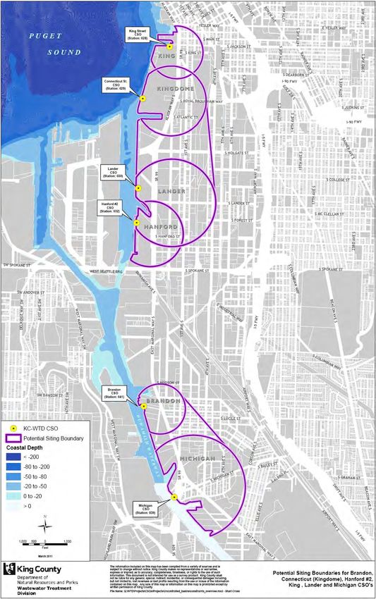
4.1 Model Griid
The moddel domain exxtends from the Green River
R at Aubburn (River Mile
M 32.0) too a line betw
ween
Magnoliaa and Alki in
n outer Elliott Bay (Figuure 4).
Fig
gure 4. Exten
nt of EFDC Model
M Grid
TM 750: Sediment
S Dep
position and Contamination
C n Potential fro
om Treated CSO
C Discharg
ges 21Previous work in simulating sediment accumulation from CSO discharges has shown that a
model grid with a spatial scale similar to the size of the discharge outlet can result in realistic
predictions of sediment accumulation rates (Battelle 2006; Schock 2011). To simulate both the
overall transport through the Duwamish-Elliott Bay system and the dynamics at each CSO, the
model grid was locally refined around each CSO discharge.
The basic grid structure consisted of 6,020 model cells that were 138 by 340 feet in the Lower
Duwamish Waterway and 103 by 265 feet in the East Waterway. The grid cells progressively
increased toward the boundaries in Elliott Bay and the Green River. At each CSO discharge
location, the base grid was deformed to allow a hemispherical grid to be inset. This
hemispherical insert was set to be eight model cells wide. A conformal mapping of a rectangle to
the hemisphere provided a grid that matched the base grid along the edges of the hemisphere
while having a model cell spacing of 6 feet at the point of discharge.
4.2 CSO Discharge Locations
State regulations require treated CSO discharges to be from a submerged outfall. Although
outfalls constructed to convey these discharges may terminate offshore, the Michigan, Hanford
and Kingdome CSO discharges were modeled at the edge of the waterway to provide
conservative results for this analysis (Figure 5):
• The refined model grid around the Michigan CSO is illustrated in Figure 6. The extent
of the model grid was not altered, resulting in model cells that would be above the
water surface for part of the tidal cycle. Since the CSO discharge is required to be
submerged, the model cells directly offshore from the discharge point were deepened to
a depth of 3.0 meters below mean sea level (0.98 meters below mean lower low water
(MLLW)).
• The refined model grid around the Hanford CSO is illustrated in Figure 7. The
discharge location is slightly south of the existing Hanford CSO discharge in order to
accommodate the grid refinements without excessively deforming the geometry of slip
27 to the north. The shoreline at this location consists of a pier face, so no adjustments
were required to ensure sufficient water depth at all tidal conditions. Details of the
refined model grid at the discharge location are illustrated in Figure 8.
• The refined model grid around the Kingdome CSO is illustrated in Figure 9. The
discharge location is slightly north of the existing Kingdome CSO discharge in order to
accommodate the grid refinements without excessively deforming the geometry of slip
36 to the south. The shoreline at this location consists of a riprapped embankment, so
no adjustments were required to ensure sufficient water depth at all tidal conditions.
Modeling the CSO discharge at the shoreline creates the minimum distance for particles to settle
before reaching the water bottom, thus minimizing the dispersion of particles and increasing
sedimentation rates.
Treated and untreated overflows for each CSO were assumed to be discharged at the same
location. A CSO treatment facility could have a new outfall and discharge point for treated flows,
which would reduce sediment accumulation rates; assuming the same location for treated and
untreated discharges results in a conservative prediction for sediment concentrations.
TM 750: Sediment Deposition and Contamination Potential from Treated CSO Discharges 22You can also read