Self-organized nonlinear gratings for ultrafast nanophotonics
←
→
Page content transcription
If your browser does not render page correctly, please read the page content below
Self-organized nonlinear gratings for ultrafast nanophotonics
                                                            Daniel D. Hickstein,1, a) David R. Carlson,1 Haridas Mundoor,2 Jacob B. Khurgin,3 Kartik Srinivasan,4
                                                            Daron Westly,4 Abijith Kowligy,1 Ivan Smalyukh,2, 5, 6 Scott A. Diddams,1, 7 and Scott B. Papp1, 7
                                                            1)
                                                               Time and Frequency Division, National Institute of Standards and Technology, Boulder, CO 80305, U.S.A.
                                                            2)
                                                               Department of Physics and Soft Materials Research Center, University of Colorado, Boulder, CO 80309, U.S.A.
                                                            3)
                                                               Department of Electrical and Computer Engineering, Johns Hopkins University, Baltimore, MD 21218, U.S.A.
                                                            4)
                                                               Center for Nanoscale Science and Technology, NIST, Gaithersburg, MD 20899, U.S.A.
                                                            5)
                                                               Department of Electrical, Computer, and Energy Engineering, University of Colorado, Boulder, CO 80309, U.S.A.
                                                            6)
                                                               Renewable and Sustainable Energy Institute, NREL and University of Colorado, Boulder, CO 80309, U.S.A.
                                                            7)
                                                               Department of Physics, University of Colorado, Boulder, CO, 80309, U.S.A.
                                                            (Dated: 21 June 2018)
                                                            Modern nonlinear optical materials allow light of one wavelength be efficiently converted into light at another
arXiv:1806.07547v1 [physics.optics] 20 Jun 2018

                                                            wavelength. However, designing nonlinear optical materials to operate with ultrashort pulses is difficult,
                                                            because it is necessary to match both the phase velocities and group velocities of the light. Here we show that
                                                            self-organized nonlinear gratings can be formed with femtosecond pulses propagating through nanophotonic
                                                            waveguides, providing simultaneous group-velocity matching and quasi-phase-matching for second harmonic
                                                            generation. We record the first direct microscopy images of photo-induced nonlinear gratings, and demonstrate
                                                            how these waveguides enable simultaneous χ(2) and χ(3) nonlinear processes, which we utilize to stabilize a
                                                            laser frequency comb. Finally, we derive the equations that govern self-organized grating formation for
                                                            femtosecond pulses and explain the crucial role of group-velocity matching. In the future, such nanophotonic
                                                            waveguides could enable scalable, reconfigurable nonlinear optical systems.

                                                  I.   INTRODUCTION                                               a bulk quadratic nonlinearity (χ(2) ), irradiation with a
                                                                                                                  laser can form permanent electric fields in the material,
                                                     Nonlinear light–matter interactions can convert pho-         which act on the material’s cubic nonlinearity (χ(3) ) to
                                                                                                                                                                    (2)
                                                  tons to new frequencies, and serve as fundamental               produce an effective quadratic nonlinearity χeff . More-
                                                  tools for laser science1 , telecommunication2 , quantum         over, since this induced electric field is formed via the
                                                  computation3 , and other disciplines across science and         interference of the fundamental with its own second har-
                                                  technology. As these applications become increasingly           monic (Fig. 1a), the direction of the field automatically
                                                  commonplace4 , there is a need for nonlinear optical plat-      switches with the correct periodicity for the QPM of sec-
                                                  forms that are small, easy to fabricate, low cost, and          ond harmonic generation (SHG). While this technique
                                                  efficient. Achieving high conversion efficiency requires        provides a simplified method for fabricating a nonlinear
                                                                                                                                                 (2)
                                                  matching the phase velocities of each wavelength of light       grating for SHG, the low χeff of SONGs in SiO2 lim-
                                                  used in the nonlinear interaction. In some cases, a fortu-      its the total conversion efficiency. More recently, the
                                                  itous material birefringence can provide a mechanism for        SONG concept has been reinvigorated through the ob-
                                                  this phase-velocity matching, but in many cases, quasi-         servation of photo-induced SHG in nanophotonic waveg-
                                                  phase-matching (QPM) techniques must be used instead.           uides made from silicon nitride (Si3 N4 , hereafter SiN)9,10 ,
                                                  QPM typically involves periodically switching the nonlin-       which offer strong spatial confinement of the light, mas-
                                                  earity of the material on the micrometer scale, however,                                                         (2)
                                                                                                                  sively scalable fabrication, and an improved χeff 10 . How-
                                                  such small features are often difficult to fabricate, and       ever, all previous implementations of photo-induced SHG
                                                  are only possible in certain materials. When femtosecond        (in both SiO2 and SiN) were realized under conditions
                                                  pulses are used for nonlinear optics, achieving the best        of strong group-velocity mismatch, limiting the phase-
                                                  performance becomes doubly challenging because, in ad-          matching bandwidth, as well as the conversion efficiency
                                                  dition to phase-velocity matching, group-velocity match-        for femtosecond pulses.
                                                  ing must also be maintained. Meeting these two con-
                                                  ditions simultaneously is usually difficult and failing to        Here we show that dispersion-engineered SiN photonic
                                                  do so results in limited conversion efficiency or temporal      waveguides, which are currently enabling breakthroughs
                                                  broadening of the ultrashort pulses.                            for ultrafast χ(3) nonlinear optics11–15 , can also serve as
                                                     To avoid the difficulties of directly fabricating QPM        a versatile platform for χ(2) nonlinear optics with fem-
                                                  materials, it is possible the use laser light to generate       tosecond pulses. Leveraging the high effective-index-
                                                  “self-organized nonlinear gratings” (SONGs), which can          contrast of air-top-clad SiN waveguides12 , we achieve
                                                  provide QPM for nonlinear processes5–8 . For example,           group-velocity matching for SHG by engineering the
                                                  in materials such as SiO2 that do not normally exhibit          waveguide cross section. Under these conditions, the for-
                                                                                                                  mation of a SONG proceeds on the timescale of a few
                                                                                                                  10s of seconds and results in a QPM grating that sup-
                                                                                                                  ports the entire bandwidth of the femtosecond pulse with
                                                  a) Electronic   mail: danhickstein@gmail.com                    high conversion efficiency. Our model of photo-induced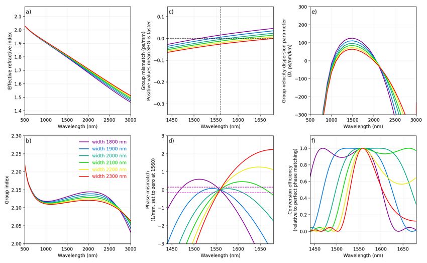
2

                                                                  1560 nm and couple approximately 40 mW (400 pJ at
                                                                  100 MHz repetition rate) into 12-mm-length, 650-nm-
                                                                  thickness silicon nitride waveguides11,12 that have an
                                                                  SiO2 bottom-cladding but air-cladding on the top and
                                                                  sides. After a build-up time of a few 10s of seconds
                                                                  (see Supplemental Fig. S9), we observe broadband SHG
                                                                  with ∼1% total conversion efficiency (Fig. 2). Once
                                                                  the waveguide has been prepared, second harmonic light
                                                                  appears immediately upon turning the laser on. How-
                                                                  ever, if the laser power is increased above approximately
                                                                  60 mW, the supercontinuum generation process12,16 pro-
                                                                  duces strong orange light (near 600 nm) and the SHG
                                                                  process is quickly quenched. However, decreasing the
                                                                  power below 40 mW allows the second harmonic to build
                                                                  up once again. This behavior indicates that the SHG re-
                                                                  sults from the formation of a SONG through the coherent
                                                                  photogalvanic effect7,9,10 .
                                                                     While the exact microscopic mechanism that forms
                                                                  the static electric fields in SiN is not yet known, recent
                                                                  studies9,10 have proposed that the separation of electrons
FIG. 1.       Self organized nonlinear grating (SONG)             and holes results in the static electric field. For the
formation in a silicon nitride (SiN) nanophotonic                 field to build-up in the waveguide between laser pulses
waveguide. a) The interference of fundamental and second-         – and to remain permanently in the material – elec-
harmonic (SH) light forces positive charges to one side of the    trons and holes must be stabilized at trap sites in the
waveguide and negative charges to the other, forming a static     material. SiN is known to provide a high density of
electric field, enabling an effective χ(2) . The phase walk-      trap sites, which may hold electrons for more than 100
off between the two fields switches the direction of the elec-
                                                                  years17 . Consequently, SiN has been used as a nonvolatile
tric field, automatically generating a self-organized nonlinear
grating with the correct periodicity to provide quasi-phase-      computer memory18 . Our SiN was deposited via low-
matching for the SHG process. The geometry of the waveg-          pressure chemical vapor deposition (LPCVD), which has
uide provides group-velocity matching, allowing for enhanced      been shown to provide a higher density of trap sites than
SH conversion efficiency. b) An second-harmonic-generation        SiN deposited via plasma-enhanced CVD (PECVD)19 .
(SHG) microscopy image reveals the periodic modulation of            Consistent with previous descriptions of SONG forma-
the effective χ(2) . c) An SHG microscopy image of the same       tion via trap-sites in SiN9,10 , we find that the generation
waveguide with perpendicular polarization reveals a double-       of visible-wavelength photons through the supercontin-
lobed structure, confirming the charge localization.              uum generation process can lead to the suppression of
                                                                  the SHG process, presumably by promoting trapped elec-
                                                                  trons to the conduction band and erasing the SONG.
QPM is verified through the use of SHG microscopy to              Similarly, a UV lamp focused on top of the waveguide
make the first direct observation of a SONG. Further-             can also lead to erasure (see Methods). Fortunately, the
more, we derive the equations that govern SONG forma-             gratings appear to be unaffected by ambient laboratory
tion for femtosecond pulses and confirm the crucial role of       light, even after several days of continuous illumination.
group-velocity matching. Finally, we demonstrate that a
suitably prepared SiN waveguide can simultaneously gen-
erate light at the second-harmonic wavelength via χ(2)            B.   Group velocity matching
and χ(3) pathways, enabling f –2f self-referencing of a
laser frequency comb. This represents the first f –2f sta-
bilization of a frequency comb using a single amorphous              In contrast to the previous studies of photo-induced
material, and demonstrates how photonic waveguides can            SHG in SiN waveguides9,10 , which observed SHG to
serve as an appealing platform for both χ(2) and χ(3) non-        higher-order modes in any waveguide, regardless of ge-
linear optics with ultrafast sources.                             ometry, we only generate second harmonic across a small
                                                                  range of waveguide widths. This difference is a result
                                                                  of group-velocity matching, with the strongest SHG ap-
                                                                  pearing for waveguide widths that allow the fundamental
II.   RESULTS AND DISCUSSION
                                                                  and the second harmonic to travel with the same group
                                                                  velocity. Importantly, the SHG from our group-velocity-
A.    Photo-induced second harmonic generation                    matched waveguides has an output mode that does not
                                                                  contain any nodes (Fig. 2a, inset), indicating that the
   We generate ∼200-fs pulses using a compact Er:fiber            second harmonic is generated in the fundamental quasi-
laser frequency comb with a center wavelength of                  transverse-electric (TE00 ) mode.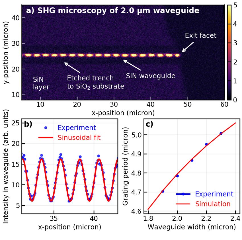
3

                                                              plications, which generally prefer a beam profile without
                                                              nodes.
                                                                 If femtosecond pulses are instead used to form the
                                                              SONG, the situation can be reversed, because the phase-
                                                              mismatch must be considered across the entire band-
                                                              width of the pump. Because phase matching to higher-
                                                              order modes is intrinsically narrowband, there is strong
                                                              group-velocity walkoff between the fundamental and
                                                              higher-order modes. However, if a mode has perfect
                                                              group-velocity matching, every wavelength in the pump
                                                              spectrum has the same phase mismatch for SHG (neglect-
                                                              ing higher-order dispersion), resulting in this mode being
                                                              favored. Some of our waveguides achieve group-velocity
                                                              matching to the fundamental mode, and consequently,
                                                              our broad bandwidth femtosecond pulses preferentially
                                                              form a grating with the correct periodicity to provide
                                                              QPM for SHG to the fundamental mode. This is of crit-
                                                              ical importance, because, as we discuss later, the gener-
                                                              ation of SHG in the fundamental mode allows for good
                                                              spatial overlap with light generated via supercontinuum
                                                              generation.
                                                                 The wavelength where group-velocity matching for
                                                              SHG occurs can be tuned by changing the waveguide di-
                                                              mensions (Fig. 2d). In our case, the 2000-nm waveguide
                                                              offers the lowest group-velocity mismatch at the 1560-nm
                                                              center wavelength of our laser. However, since we have a
                                                              broadband pump, we find that we can generate SHG from
                                                              waveguides with widths between 1900 and 2300 nm. As
                                                              the width is increased, the peak of the second harmonic
FIG. 2.        Second harmonic generation in amor-            moves to longer wavelengths (Supplemental Fig. S7), in
phous silicon-nitride waveguides using femtosecond
                                                              agreement with the trend in the group-velocity matching
pulses. a) Experimentally, femtosecond pulses with a cen-
ter wavelength of 1560 nm generate second-harmonic light      (Fig. 2d and Supplemental Fig. S8).
near 780 nm. The dashed red line is the fundamental spec-        Because the SONG can persist indefinitely, it can be
trum plotted at half the wavelength to demonstrate that the   used with other laser sources having a similar wave-
bandwidth is preserved. Inset: The output mode is in the      length. We use this ability to directly map the phase-
fundamental quasi-transverse-electric (TE00 ) mode. b) The    matching bandwidth of the gratings by using a few-
group index of bulk silicon nitride monotonically decreases   milliwatt continuous-wave (CW) laser to generate SHG
with wavelength, making group-velocity matching impossi-      from each waveguide (Supplemental Fig. S6). We ob-
ble. However, the group index of a 650×1970-nm silicon-       serve broadband SHG, in some cases spanning 60 nm,
nitride waveguide provides perfect group velocity matching    by tuning the CW laser from 1520 to 1620 nm for each
for 1560-nm SHG. c) SHG is favored at relatively low input
                                                              waveguide, confirming that group-velocity matching has
pulse intensities. At input powers over ∼60 mW, supercon-
tinuum generation takes place and no SHG is seen. d) The      been achieved. Additionally, as expected from Fig. 2d,
fundamental-mode wavelength where group-velocity match-       the peak conversion efficiency moves to longer wave-
ing with the second-harmonic is achieved increases with in-   lengths with increasing waveguide width. Thus, the
creasing waveguide width.                                     group-velocity matching condition provides advantages
                                                              for both femtosecond pulses and situations where tun-
                                                              ability is required for CW frequency conversion.
   For any waveguide SONG, the initial formation begins
with a competition between the various spatial modes
(fundamental and higher order) of the waveguide to de-        C.   Microscopy of self-organized nonlinear gratings
termine which second-harmonic mode will be favored9,10 .
When pulses longer than a few picoseconds are used, the         To confirm the presence of periodic χ(2) gratings in
second harmonic is generated into the higher order mode       our waveguides, we prepare the SONGs using the afore-
that offers the lowest phase-mismatch. However, produc-       mentioned procedure, irradiating each waveguide for ap-
ing SHG into a higher order mode can be inconvenient,         proximately 10 minutes. We then transport the waveg-
in part because it may reduce the conversion efficiency       uides several kilometers to another laboratory, where
by decreasing the spatial overlap with the fundamental        we employ a SHG microscope (see Methods) to record
mode, but also because it complicates downstream ap-          the first direct images of a SONG. While the SHG ex-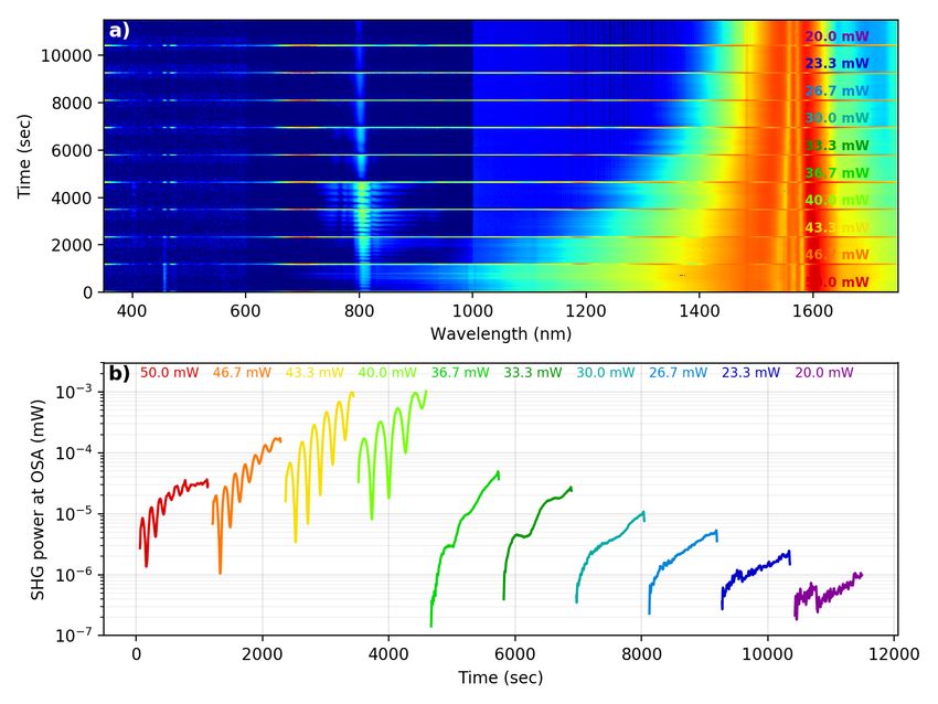
4

                                                                              (2)
periment creates the periodic grating by propagating          calculate the χeff to be 0.5 pm/V for the 2100 nm waveg-
1560-nm pulses along the waveguide (from left-to-right        uide.
in Fig. 1b,c), the microscope probes the sample from top         It is likely that the lengths of the SONGs that we ob-
to bottom with 870-nm pulses. The intensity of the emit-      serve are limited by the broad bandwidth of our laser
ted second-harmonic light is measured, and the laser is       pulses, and that much longer gratings could be produced
raster-scanned across the chip to form a two-dimensional      if narrower-bandwidth pulses propagated through longer
image of the waveguide and the surrounding material.          waveguides. A longer grating would provide a narrower
While most of the SiN material appears dark, the waveg-       phase-matching bandwidth, but greatly enhanced con-
uides that exhibit strong SHG appear bright as a re-          version efficiency.
                                (2)                                                       (2)
sult of the strong induced χeff (Fig. 1b,c and Supple-           Using our calculated χeff , we can make a comparison
mental Fig. S4). The observed periodicity of the SONG         to a periodically poled lithium niobate (PPLN) waveg-
matches the period expected for QPM of 1560-nm SHG            uide with χ(2) = 50 pm/V and an effective mode area
(Supplemental Fig. S3). Moreover, we observe that the         of 100 µm2 . To our knowledge, such PPLN waveguides
SONGs extend for 2–6 mm (depending on the waveguide           provide the highest conversion efficiency for any commer-
width), and that none of the SONGs exhibit any signif-        cially available nonlinear optical device. Fig. 3a shows
icant change in period along the length, confirming that      the maximum conversion efficiency achievable, while pre-
group-velocity matching, and not variations in the grat-      serving the full bandwidth of the pulse. As the pulse
ing period, is responsible for the broad-bandwidth SHG        duration becomes longer, a SiN waveguide should out-
(Supplemental Fig. S5). Our results are in general agree-     perform a PPLN waveguide, since the group-velocity
ment with what has been observed when SONGs in SiO2           matching allows a longer grating to be supported. Given
were visualized using electric-field-sensitive HF etching     the optimal length for both devices, a SiN waveguide
techniques20 .                                                should outperform a PPLN waveguide for pulse durations
   To further characterize the SONG, we record numer-                                              (2)
                                                              longer than about 30 fs. If the χeff could be further in-
ous SHG-microscopy images along the length of several         creased, SONGS based on SiN could enable SHG with
waveguides and fit a sinusoidal function to the integrated    even lower pulse energies, enabling frequency conver-
SHG intensity (Supplemental Fig. S5). We find that            sion of un-amplified electro-optic21 and microresonator-
the intensity of the SONG follows a sigmoid function,         based22 frequency combs. The dots in Fig. 3a represent
where the SONG is not observable at the entrance facet,       the conversion efficiency required to achieve 10% conver-
smoothly increases at some point along the waveguide          sion for various input pulse energies and durations.
length, and then reaches a constant value that is main-
tained until the exit facet. This behavior suggests that
the SONG reaches a saturation condition, where the fun-       E.   Analytical description of grating formation
damental and SHG can no longer increase the inten-
sity of the SONG. The origin of this saturation is not
clear, though several possibilities exist. For example,         While several models exist for photo-induced grating
the saturation may represent a condition where nearly         formation in the case of CW light7,23,24 , to our knowl-
all of the available trap sites in the material have been     edge, no theoretical treatment has been attempted for
occupied. Alternatively, it may correspond to a situa-        femtosecond pulses. Thus, we explore the photo-induced
tion where the static field is so large that it can cause     grating formation process analytically, following the pro-
charges to leave trap sites. Finally, it is possible that     cedure of Anderson et al.7 , and present the complete
fundamental, second-harmonic, or third-harmonic pho-          analysis in Supplemental Materials Section S1. By as-
tons promote trap-site electrons to the conduction band,      suming that we can model the total photo-induced grat-
and that the saturation effect occurs when an equilib-        ing as a coherent sum of contributions from all of the
rium is reached between the rate of promoting electrons       individual frequencies, we find that the second-harmonic
to trap sites and the rate of promoting trap-site electrons   pulse energy increases from the noise level at the input
to the conduction band. Future experiments that exam-         end U2 (0) to the output value of U2,out = U2 (0) exp(G)
ine that nature of the saturation may provide insight into    with the total logarithmic gain for SHG given by
           (2)
how the χeff may be increased.
                                                                                                       −(∆v δωz 0 )2
                                                                                                 1
                                                                                                     e 2(1+δω4 z02 )
                                                                                            Z
                                                                       G(δω, ∆v ) ∼ G0 δω            √               dz 0 ,   (1)
D.   Conversion efficiency                                                                   0         1 + δω 4 z 02
                                                                                 √
  For some waveguides, the SHG conversion exceeds                where δω = ∆ω δβL is the normalized pulse band-
0.005 %/Watt of peak power (Supplemental Fig. S6),            width, ∆ω is the actual pulse bandwidth, L is the length
which is excellent conversion efficiency for a device that    of the waveguide, and δβ = β2ω0 − βω0 is the difference
provides SHG across such a large bandwidth. Since we          in group-velocity dispersion (GVD) at the fundamental
                                                                                                              p
know the length of the grating from the microscopy ex-        and second-harmonic frequencies. ∆v = δvg−1 L/δβ
periments, we can use Eqs. 9 and 10 from Ref. 10 to           is the normalized group-velocity mismatch, and δvg−1 =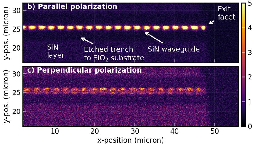
5
−1 −1
vg,2ω0
−vg,ω 0
is the (inverse) group-velocity mismatch be-
tween the fundamental and the SHG. The coefficient G0
incorporates several material characteristics, including
the effective coherent photoinjection coefficient, third-
order nonlinear susceptibility, momentum scattering and
recombination times, trapping cross-section, and the ef-
fective cross-section of the waveguide, which makes theo-
retical estimate of G0 difficult. However, comparing our
results with those of Ref. 7, it is not unreasonable to as-
sume that our gain is similar, i.e. on the order of 40 dB.
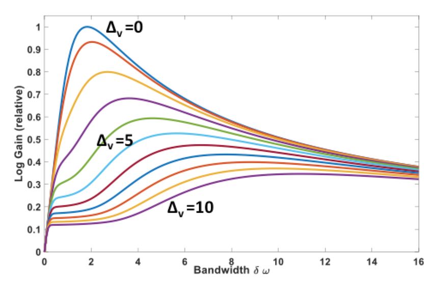
Eq. 1 indicates that better group-velocity matching
(lower ∆v ) allows for larger maximum gain. More-
over, better group-velocity matching allows for SHG with
shorter pulses, explaining why previous studies observed
SHG with picosecond pulses, and how the group-velocity
matching enabled by nanophotonic waveguides allows for
SHG with femtosecond pulses (Fig. 3b,c).
F. Simplified frequency comb stabilization
A particular advantage of SiN nanophotonic waveg-
uides is that they exhibit simultaneous supercontin-
uum generation (χ(3) ) and SHG (χ(2) ), which allows for
f -2f self-referencing of frequency combs. In previous
experiments25 , waveguides made from aluminum nitride,
a material with bulk χ(3) and χ(2) provided both SHG
FIG. 3. Analytical estimate of SHG with SiN waveg- and supercontinuum generation and allowed for a simpli-
(2)
uides. a) Using the χeff obtained in this study and the cal- fied scheme for self-referencing. However, nJ pulse ener-
culated dispersion of a 1953×649-nm SiN waveguide (which gies were required, since SHG to the fundamental mode
offers group-velocity matching at 1560-nm), we can plot the was strongly phase mismatched and was consequently
conversion efficiency of SiN waveguides as a function of the very dim. In contrast, in the case of SiN SONGs, the
pulse duration. The red line indicates the performance of
SHG is fully quasi-phase-matched and the conversion ef-
the SiN waveguides as demonstrated in this work, while the
green line represents the potential performance if an increase
ficiency is much higher, which allows lower pulse energies
(2) to be used. For production of both SHG and supercon-
in material χ(3) or static electric field could enable χeff to
be increased to 4.71 pm/V. In comparison to a commercial tinuum at 780-nm, the pulse energy must be set appro-
SHG waveguide made from periodically poled lithium nio- priately. If it is too low, then insufficient supercontinuum
bate (PPLN, blue), the SiN waveguides provide a τ 4 scaling is generated, and if it is too high, then the SHG intensity
of the conversion efficiency rather than a τ 2 scaling of a group- is diminished. Fortunately, a regime exists where both
velocity-mismatched material. b) The gain for SHG as a func- supercontinuum and SHG are generated with sufficient
tion of the input pulse bandwidth δω for various values of the intensity to detect the carrier–envelope-offset frequency
normalized group-velocity mismatch ∆v demonstrates that (fceo ) with ∼30 dB signal-to-noise ratio (SNR, Fig. 4).
higher gain is provided by smaller values of group-velocity We stabilize fceo by feeding back to the laser current and
mismatch. In general, when the group-velocity mismatch is verify that performance equivalent to a traditional f -2f
higher, a smaller pulse bandwidth is required to reach higher
interferometer can be achieved by counting the in-loop
gain. However, as the pulse bandwidth is increased to very
large values, the gain increases once again, because now light
beat note with a frequency counter12 .
is present at the frequency where group-velocity matching is
achieved. c) For photo-induced SHG with femtosecond pulses,
the highest conversion efficiency will be realized through per- III. OUTLOOK
fect group-velocity matching.
We have performed a proof-of-principle demonstra-
tion, showing that nanophotonic waveguides can provide
broadband SHG for femtosecond pulses. Looking to the
future, there are several open questions and possible av-
enues for improvement. For instance, it should be pos-
sible to achieve much higher conversion efficiencies than
(2)
demonstrated here by increasing either χeff or the length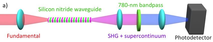
6

                                                                      amounts to a waveguide that exhibits low and flat GVD
                                                                      over a broad spectral region. Fortunately, nanophotonic
                                                                      waveguides provide exceptional control over GVD, and
                                                                      several studies27,28 have shown that “slot waveguide”
                                                                      geometries can be used to provide ultra-flat GVD pro-
                                                                                      (2)
                                                                      files. If both χeff and the waveguide length can be sig-
                                                                      nificantly increased, nanophotonic waveguides could en-
                                                                      able nonlinear optics with ultra-low pulse energies, which
                                                                      would have numerous applications, ranging from quan-
                                                                      tum computing3 to microresonator frequency combs22 .

                                                                      IV.   CONCLUSION

                                                                         We have shown that nanophotonic waveguides can pro-
                                                                      vide quasi-phase-matching for nonlinear processes via
                                                                      self-organized nonlinear grating formation. Unlike pre-
                                                                      vious observations of such gratings, we form the grat-
                                                                      ings using femtosecond pulses, and observe broadband
                                                                      second harmonic generation to the fundamental mode of
                                                                      the waveguide. These nanophotonic waveguides provide
                                                                      both quasi-phase-matching and group-velocity match-
                                                                      ing for second harmonic generation, opening the door
                                                                      for dispersion-engineered χ(2) ultrafast nonlinear op-
FIG. 4. Frequency comb stabilization through one-
                                                                      tics in amorphous waveguides. Using second-harmonic-
step f -2f self-referencing. a) In contrast to a typical f -          generation microscopy, we record the first direct images
2f self-referencing experiment, which requires separate SHG           of self-organized nonlinear gratings. Additionally, by an-
and supercontinuum-generation media, a single SiN waveg-              alytically deriving the equations that govern the forma-
uide provides both f and 2f light, which can be selected using        tion of the nonlinear gratings, we quantify the role of
a simple filter and detected with a silicon photodetector. b)         group-velocity, and group-velocity-dispersion mismatch
The input power is set at a level that provides both super-           in the self-organization process. Finally, we demonstrate
continuum and second-harmonic light near 800 nm. c) The               the utility of such nanophotonic waveguides by self-
carrier–envelope offset frequency (fceo ) is detected with 30 dB      referencing a laser frequency comb with a single waveg-
signal-to-noise ratio, which is sufficient for stabilizing the fre-   uide. In the future, longer and more nonlinear waveg-
quency comb without phase slips. c) The Allan deviation of
                                                                      uides will enable high-efficiency nonlinear optics in situ-
the locked fceo (recorded with a separate photodetector and
frequency counter) confirms that fceo has been stabilized to          ations previously considered impossible.
a level suitable for precision measurements.
                                                                      ACKNOWLEDGMENTS
                             (2)
of the waveguide. The χeff could be optimized via sev-
                                                                        We acknowledge Gregory Moille, and the NIST Boul-
eral methods including increasing the material χ(3) , en-             der Editorial Review Board for providing helpful feed-
gineering the material to support higher electric fields,             back on this manuscript. We thank Kevin Dorney and
                                             (2)
or finding a material that has a stronger χeff response               Jennifer Ellis, Henry Kapteyn, and Margaret Murnane
via slight re-arrangement of the atomic positions. As an              for the timely loan of a polarizer. We acknowledge Nor-
                                                    (2)
example of how a high χ(3) can result in a high χeff , a              man Sanford for insightful discussions. This work is sup-
recent study26 has shown that silicon, a material with                ported by AFOSR under award number FA9550-16-1-
a strong χ(3) , can be biased with electrodes to enable a             0016, DARPA (DODOS and ACES programs), NIST,
  (2)
χeff of 41 pm/V.                                                      and NRC. This work is a contribution of the U.S. gov-
   Increasing the length of the waveguide first requires              ernment and is not subject to copyright in the U.S.A.
that the waveguide loss is low. Fortunately, recent ef-
forts have realized SiN waveguides with losses on the or-
der of 1 dB/meter13 , and suggest that the losses may                 V.    METHODS
be decreased orders-of-magnitude further before reach-
ing the material limit. Second, increasing the length                 A.    Waveguide design
of the waveguide while preserving the bandwidth of the
SHG requires that the waveguide offers low phase mis-                  The waveguide fabrication took place at NIST in
match over the entire bandwidth of the input pulse. This              Gaithersburg, Maryland. The waveguides are com-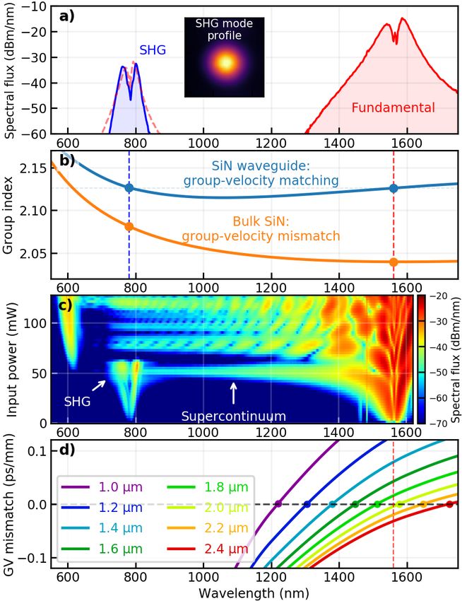
7

posed of Si3 N4 deposited via low-pressure-chemical-             referencing, which separately generates the supercontin-
vapor-deposition (LPCVD) on top of a 3 µm thermal                uum light in one material and the second harmonic light
SiO2 layer, which is supported by a silicon substrate.           in another material12 .
Two different chips of waveguides were investigated for             The light emitted by the waveguide was collimated
SHG. One sample consists of 650-nm thick “air-clad”              with a microscope objective with a numerical aperture
waveguides without side or top cladding. The other sam-          (NA) of 0.85 (Newport M60x) and filtered with a 780-
ple consists of 700-nm thick waveguides that are “air-           nm bandpass filter (Thorlabs FB-780-10). A beamsplit-
clad” in the central region, but have an SiO2 top and            ter directed the light to two separate silicon avalanche
side cladding in the first and last 1 mm of the waveg-           photodiodes (APD, Thorlabs APD430A and APD210).
uide length to improve the coupling efficiency. Details          The electrical signal from the first photodiode was con-
regarding the 600-nm thickness waveguides are provided           nected to a Red Pitaya field-programmable-gate-array
in Ref. 11, while details of the 700-nm thickness waveg-         (FPGA) board running the “Frequency comb digital-
uides are provided in Ref. 12. The waveguide modes (and          phase-locked-loop” firmware33,34 , which was used to feed
their effective indices) are calculated using a vector finite-   back to the oscillator pump-diode current in order to sta-
difference modesolver29,30 , using published refractive in-      bilize fceo . The electrical signal for the second APD was
dices for Si3 N4 31 and SiO2 32 .                                connected to a Λ-type frequency counter, which provided
                                                                 an “electrical out-of-loop” confirmation of the fceo stabi-
                                                                 lization.
B.   Second harmonic generation

   Second harmonic generation experiments were com-              D.   Second-harmonic-generation microscopy
pleted at NIST in Boulder, Colorado. We generate sec-
ond harmonic by coupling 1560-nm light from a com-                  Second harmonic generation microscopy experiments
pact 100 MHz Er-fiber frequency comb33 into each SiN             were completed at the Smalyukh Lab at the University
waveguide. The power is adjusted using a computer-               of Colorado. A Ti:sapphire laser (Coherent Chameleon
controlled rotation-mount containing a half-waveplate,           Ultra II) was used to generate 140-fs pulses with a cen-
which is placed before a polarizer. The polarization is          tral wavelength of 870 nm at an 80-MHz repetition-rate.
set to horizontal (along the long dimension of the rect-         The laser was attenuated so that, at the sample, the av-
angular waveguide) and excites the lowest order quasi-           erage power was 6 mW, corresponding to a pulse en-
transverse-electric (TE00 ) mode of the waveguide.               ergy of 75 pJ. The beam enters an inverted microscope
   Interestingly, in some cases, we see strong temporal os-      system (Olympus IX81) and is focused onto the sam-
cillations in the intensity of the second harmonic. Similar      ple using an Olympus UPlanFLN 40x objective with
oscillations were also observed in other studies of silicon      NA=0.75, providing a peak intensity of approximately
nitride waveguides9,10 . In our waveguides, the oscilla-         4.7 × 10¹⁰ W/cm2 , assuming a diffraction-limited spot
tions typically become faster when the laser intensity is        size. The focused spot was raster-scanned across the
increased (Supplemental Fig. S9). Additionally, they are         sample using a galvo mirror system (Olympus Fluorview
nearly absent for the waveguides that exhibit the best           FV300). The reflected second-harmonic light propagates
group-velocity matching, suggesting that they are related        back into the galvo-mirror system where it is collected
the the group-velocity matching conditions. We suspect           with a photomultiplier tube. Images were collected at a
that these oscillations result from slight changes in the        rate of ∼32,000 pixels/second and a size of 512 × 512 pix-
period of the grating during the formation process. For          els, for an image acquisition rate of ∼9 s per image. The
example, an initial grating might form with a period that        images are averaged using a 10-frame Kalman filter, for
phase-matches SHG at the peak of the pump spectrum.              a total acquisition time of ∼90 s per averaged image.
Over time, the grating may slightly change period to pro-           Generally, the SHG microscopy experiment did not
vide phase matching for the wavelength that experiences          significantly alter the self-organized gratings, indicating
the best group-velocity matching in the waveguide.               that it may be possible to record such images in situ,
                                                                 while the grating is forming. However, in several cases,
                                                                 when the laser was left to raster over a small region for
C.   Frequency comb stabilization                                many minutes, we noticed a slow decrease in the inten-
                                                                 sity of the SHG being emitted from the waveguide, in-
  We used the SiN waveguides to provide a simplified,            dicating that the grating was being erased. It is not
low-power method to stabilize our Er-fiber frequency             clear if the erasure is caused by the high peak intensity
comb. By setting the power level to ∼40 mW, we                   of the femtosecond pulses or simply the average power.
generate light near 780 nm via both SHG (a χ(2) pro-             Additionally, during an initial microscopy attempt, we
cess) and supercontinuum generation (a χ(3) process).            aligned the microscope by illuminating the chip with
The interference of these two pathways allows fceo to            a 100 W mercury-vapor lamp (Olympus U-LH100HG),
be detected simply by detecting the light near 780 nm.           which emits high power visible and UV light. However
This approach is in contrast to conventional f -2f self-         we found that the focused light from this lamp appeared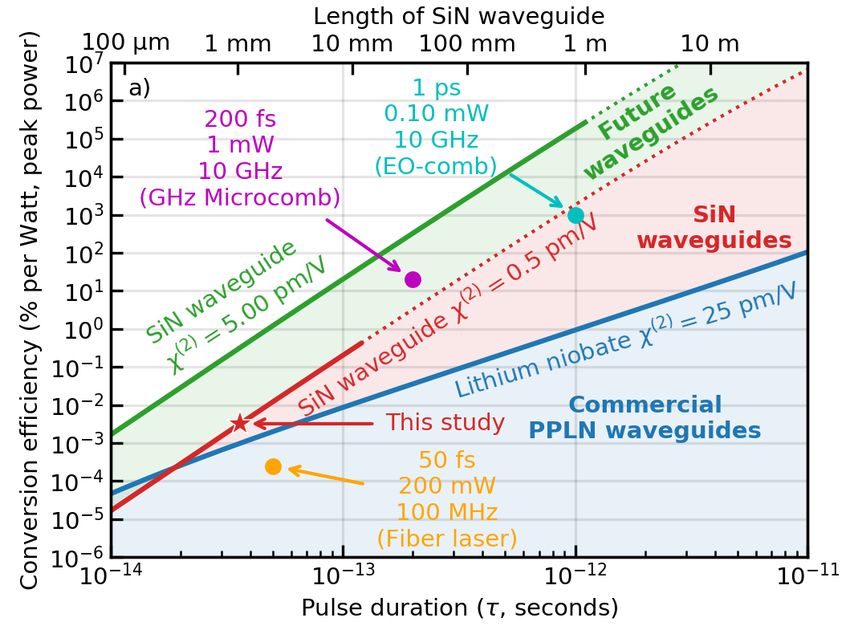
8

to rapidly erase the self-organized gratings. However,                is it intended to imply that the materials or equipment
we found that illumination with a lower-power halogen                 identified are necessarily the best available for the pur-
lamp (Olympus LG-PS2-5), which produces much lower                    pose. This work is a contribution of the United States
levels of UV light, allowed the microscope to be aligned              government and is not subject to copyright in the United
without affecting the observed SHG, indicating that irra-             States of America.
diation with high-energy photons is an effective method
for grating erasure.
                                                                      VII.    REFERENCES

E.    Estimation of the effective quadratic nonlinearity
                                                                       1 G.  New, Introduction to nonlinear optics (Cambridge University
                                                                         Press, 2011).
   Using a continuous wave (CW) laser, we can gener-                   2 T.    Schneider, Nonlinear Optics in Telecommunications
ate second harmonic from the waveguides that have been                   (Springer, 2004).
                                                                       3 M. M. Weston, H. M. Chrzanowski, S. Wollmann, A. Boston,
suitably prepared by the femtosecond-pulsed laser. Be-
                                                                         J. Ho, L. K. Shalm, V. B. Verma, M. S. Allman, S. W. Nam,
cause the CW laser doesn’t spectrally broaden as it prop-                R. B. Patel, S. Slussarenko, and G. J. Pryde, “Efficient and
agates along the waveguide, it allows an accurate mea-                   pure femtosecond-pulse-length source of polarization-entangled
surement of the SHG conversion efficiency. Addition-                     photons,” Opt. Express 24, 10869–10879 (2016).
                                                                       4 E. Garmire, “Nonlinear optics in daily life,” Opt. Express 21,
ally, since the SHG microscopy experiment provides es-
timates of the length of the grating in each waveguide,                  30532–30544 (2013).
                                                                       5 E. Dianov and D. Starodubov, “Photoinduced second-harmonic
we can estimate the effective quadratic nonlinearity of                  generation in glasses and glass optical fibers,” Optical Fiber
our SiN waveguides. According to Eq. 5.37 of Weiner35                    Technology 1, 3 (1994).
and Eq. 3.19 of Suhara and Fujimura36 , we can write the               6 M. K. Balakirev, L. I. Vostrikova, and V. A. Smirnov, “Photo-

conversion efficiency for SHG as                                         electric instability in oxide glass,” Journal of Experimental and
                                                                         Theoretical Physics Letters 66, 809–815 (1997).
                                                                       7 D. Z. Anderson, V. Mizrahi, and J. E. Sipe, “Model for second-
                        L2 d2eff    2ω02

                  η
                     =                        ,       (2)                harmonic generation in glass optical fibers based on asymmetric
                 Pω      Seff      ε0 c3 n3                              photoelectron emission from defect sites,” Optics Letters 16, 796
                                                                         (1991).
                                                                       8 R. H. Stolen and H. W. K. Tom, “Self-organized phase-matched
where η is the conversion efficiency, Pω is the peak power
of the fundamental, L is the medium length, ε0 is the                    harmonic generation in optical fibers,” Optics Letters 12, 585
                                                                         (1987).
permittivity of free space, ω0 is the frequency of the fun-            9 A. Billat, D. Grassani, M. H. P. Pfeiffer, S. Kharitonov, T. J.
damental, c is the speed of light, n is the index of the                 Kippenberg, and C.-S. Bres, “Large second harmonic generation
fundamental, Seff is the effective mode area, and the non-               enhancement in Si3N4 waveguides by all-optically induced quasi-
                      (2)                                                phase-matching,” Nature Communications 8, 1016 (2017).
linearity deff = 1/2χeff .                                            10 M. A. G. Porcel, J. Mak, C. Taballione, V. K. Schermerhorn,
   We can see from Eq. 2 that increasing the medium                      J. P. Epping, P. J. M. v. d. Slot, and K.-J. Boller, “Photo-
length is equally important to increasing deff . Re-                     induced second-order nonlinearity in stoichiometric silicon nitride
arranging Eq. 2 to solve for deff yields                                 waveguides,” Optics Express 25, 33143 (2017).
                                                                      11 D. R. Carlson, D. D. Hickstein, A. Lind, J. B. Olson, R. W.

                      s                                                 Fox, R. C. Brown, A. D. Ludlow, Q. Li, D. Westly, H. Leopardi,
                                                                         T. M. Fortier, K. Srinivasan, S. A. Diddams, and S. B. Papp,
                                                 ε0 c3 n3

                            η        Seff                                “Photonic-chip supercontinuum with tailored spectra for count-
             deff =                                         .   (3)
                           Pω        L2           2ω02                   ing optical frequencies,” Phys. Rev. Applied 8, 014027 (2017).
                                                                      12 D. R. Carlson, D. D. Hickstein, A. Lind, S. Droste, D. Westly,

Using    a     numerical     vector    finite   difference               N. Nader, I. Coddington, N. R. Newbury, K. Srinivasan, S. A.
                                                                         Diddams, and S. B. Papp, “Self-referenced frequency combs
modesolver29,30 , we calculate that the effective area for               using high-efficiency silicon-nitride waveguides,” Opt. Lett. 42,
1560-nm SHG in a 650×2100-nm waveguide is 1.20 µm2 .                     2314–2317 (2017).
                                                                      13 X. Ji, F. A. S. Barbosa, S. P. Roberts, A. Dutt, J. Cardenas,
Using the observed grating length (1.05 mm) and the
observed conversion efficiency (0.0025 %/W), we can use                  Y. Okawachi, A. Bryant, A. L. Gaeta, and M. Lipson, “Ultra-
                                                                         low-loss on-chip resonators with sub-milliwatt parametric oscil-
Eq. 3 to calculate deff = 0.25 pm/V (χ(2) = 0.5 pm/V).
                                                                         lation threshold,” Optica 4, 619 (2017).
This is in rough agreement with the value of χ(2) =                   14 A. S. Mayer, A. Klenner, A. R. Johnson, K. Luke, M. R. E.
0.3 pm/V reported by Billat, et al.9 .                                   Lamont, Y. Okawachi, M. Lipson, A. L. Gaeta, and U. Keller,
                                                                         “Frequency comb offset detection using supercontinuum genera-
                                                                         tion in silicon nitride waveguides,” Opt. Express 23, 15440–15451
                                                                         (2015).
VI.   DISCLAIMER                                                      15 M. A. G. Porcel, F. Schepers, J. P. Epping, T. Hellwig, M. Hoek-

                                                                         man, R. G. Heideman, P. J. M. van der Slot, C. J. Lee,
   Certain commercial equipment, instruments, or mate-                   R. Schmidt, R. Bratschitsch, C. Fallnich, and K.-J. Boller, “Two-
rials are identified here in order to specify the experi-                octave spanning supercontinuum generation in stoichiometric sil-
                                                                         icon nitride waveguides pumped at telecom wavelengths,” Opt.
mental procedure adequately. Such identification is not                  Express 25, 1542–1554 (2017).
intended to imply recommendation or endorsement by                    16 J. M. Dudley, G. Genty, and S. Coen, “Supercontinuum genera-

the National Institute of Standards and Technology, nor                  tion in photonic crystal fiber,” Rev. Mod. Phys. 78, 1135 (2006).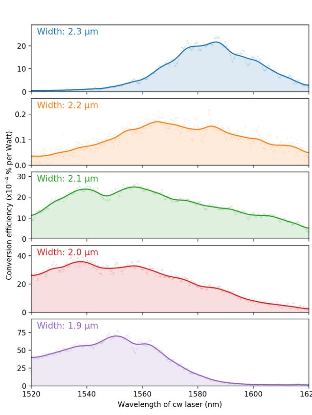
9

17 S.-D.  Tzeng and S. Gwo, “Charge trapping properties at silicon
   nitride/silicon oxide interface studied by variable-temperature
   electrostatic force microscopy,” Journal of Applied Physics 100,
   023711 (2006).
18 S. Fujita and A. Sasaki, “Dangling bonds in memory-quality sil-

   icon nitride films,” Journal of The Electrochemical Society 132,
   398–402 (1985).
19 Y. C. Park, W. B. Jackson, N. M. Johnson, and S. B. Hagstrom,

   “Spatial profiling of electron traps in silicon nitride thin films,”
   Journal of Applied Physics 68, 5212 (1990).
20 W. Margulis, F. Laurell, and B. Lesche, “Imaging the nonlinear

   grating in frequency-doubling fibres,” Nature 378, 699 (1995).
21 D. R. Carlson, D. D. Hickstein, W. Zhang, A. J. Metcalf, F. Quin-

   lan, S. A. Diddams, and S. B. Papp, “An ultrafast electro-
   optic light source with sub-cycle precision,” arXiv:1711.08429
   [physics.optics] (2017).
22 E. S. Lamb, D. R. Carlson, D. D. Hickstein, J. R. Stone,

   S. A. Diddams, and S. B. Papp, “Optical-frequency measure-
   ments with a kerr microcomb and photonic-chip supercontin-
   uum,” Phys. Rev. Applied 9, 024030 (2018).
23 B. Y. Zel’dovich and A. N. Chudinov, “Interference of fields with

   frequencies ω and 2ω in external photoelectric effect,” JETP Lett.
   50, 439 (1989).
24 N. Baranova, A. Chudinov, and B. Zel’dovich, “Polar asymme-

   try of photoionization by a field with < E 3 >6= 0. theory and
   experiment,” Optics Comm. 79, 116 (1990).
25 D. D. Hickstein, H. Jung, D. R. Carlson, A. Lind, I. Coddington,

   K. Srinivasan, G. G. Ycas, D. C. Cole, A. Kowligy, C. Fredrick,
   S. Droste, E. S. Lamb, N. R. Newbury, H. X. Tang, S. A. Did-
   dams, and S. B. Papp, “Ultrabroadband supercontinuum gener-
   ation and frequency-comb stabilization using on-chip waveguides
   with both cubic and quadratic nonlinearities,” Phys. Rev. Ap-
   plied 8, 014025 (2017).
26 E. Timurdogan, C. V. Poulton, M. J. Byrd, and M. R. Watts,

   “Electric field-induced second-order nonlinear optical effects in
   silicon waveguides,” Nature Photonics 11, 200 (2017).
27 M. Zhu, H. Liu, X. Li, N. Huang, Q. Sun, J. Wen,                and
   Z. Wang, “Ultrabroadband flat dispersion tailoring of dual-slot
   silicon waveguides,” Opt. Express 20, 15899–15907 (2012).
28 L. Zhang, Y. Yue, R. G. Beausoleil, and A. E. Willner, “Flat-

   tened dispersion in silicon slot waveguides,” Opt. Express 18,
   20529–20534 (2010).
29 A. B. Fallahkhair, K. S. Li, and T. E. Murphy, “Vector finite dif-

   ference modesolver for anisotropic dielectric waveguides,” Jour-
   nal of Lightwave Technology 26, 1423–1431 (2008).
30 L. Bolla, “Empy: Electromagnetic python,” https://github.

   com/lbolla/EMpy (2017).
31 K. Luke, Y. Okawachi, M. R. E. Lamont, A. L. Gaeta, and

   M. Lipson, “Broadband mid-infrared frequency comb generation
   in a Si3N4 microresonator,” Opt. Lett. 40, 4823–4826 (2015).
32 I. H. Malitson, “Interspecimen comparison of the refractive index

   of fused silica,” J. Opt. Soc. Am. 55, 1205 (1965).
33 L. C. Sinclair, J.-D. Deschenes, L. Sonderhouse, W. C. Swann,

   I. H. Khader, E. Baumann, N. R. Newbury, and I. Coddington,
   “Invited article: A compact optically coherent fiber frequency
   comb,” Review of Scientific Instruments 86, 081301 (2015).
34 A. Tourigny-Plante, V. Michaud-Belleau, N. Borbeau-Hebert,

   H. Bergeron, J. Genest, and J. Deschenes, “An open and flexible
   digital phase lock loop for optical metrology,” arXiv:1804.01028
   [eess.SP] (2018).
35 A. Weiner, Ultrafast Optics (Wiley, 2009).
36 T. Suhara and M. Fujimura, Waveguide Nonlinear-Optic Devices

   (Wiley, 2003).
37 J. B. Khurgin, “Generation of the terahertz radiation using chi-

   3 in semiconductor,” J. Nonlinear Optical Phys. Mat. 04, 163
   (1995).
10

                                                      Supplemental Materials
S1. THEORY OF PHOTO-INDUCED GRATING
FORMATION WITH FEMTOSECOND PULSES

  The grating formation is driven by the interaction of
the fundamental pulse E1 (t), centered at carrier fre-
quency ω0 (wavevector kω0 ) and the second-harmonic
(SH) pulse E2 (t), centered at twice the carrier frequency
2ω0 (wavevector k2ω0 )(Fig. S1). Both pulses can be rep-
resented in the frequency domain as a superposition of
monochromatic waves:
                            Z
    E1 (t) = ei(kω0 z−ω0 t) F1 (ω)ei(k1 z−ω1 t) dω1
                               Z                         (S1)
               i(k2ω0 z−2ω0 t)          i(k2 z−ω2 t)
    E2 (t) = e                   F2 (ω)e             dω2
                                                                     FIG. S1. The process of self-phase matched photoin-
                                                                     duced SHG with femtosecond (broadband) pulses.
where ω1,2 and k1,2 are the frequencies and wavevectors              The interference of two photon absorption of fundamental
relative to the carriers of the fundamental and the SH               photons at frequencies ω1 and (ω2 − ω1 ) with a single photon
respectively and F1 and F2 are the Fourier transforms of             absorption at frequency ω2 produces quantum interference
each field.                                                          current and the grating of effective χ(2) . This grating serves
   Three-wave interference of one photon near the SH                 to achieve quasi-phase-matching (QPM) for sum frequency
carrier frequency and two photons near the fundamen-                 generation with fundamental frequencies ω3 and ω4 − ω3 pro-
                                                                     ducing frequency component near SHG frequency 2ω0 .
tal carrier frequency creates a coherent, directional pho-
tocurrent Jcoh proportional to the vector potentials of
these three waves,
                                                                     DC field with a sinusoidal spatial pattern with a period
                                                                     of ∆k
   Jcoh ∝    A1 (ω1 )A1 (ω2 − ω1 )A∗2 (ω2 )ei∆k(ω1 ,ω2 )
                                                              (S2)
         ∝   iF1 (ω1 )F1 (ω2 − ω1 )F2∗ (ω2 )ei∆k(ω1 ,ω2 ) .            EDC (ω2 , z) ∼ iCF2∗ (ω2 )ei∆k(ω2 )z
                                                                                                                         (S5)
                                                                                        Z
The fact that Jcoh depends on the vector potentials and                               × F1 (ω1 )F1 (ω2 − ω1 )dω1 + c.c.,
not the electric fields37 produces a 90-degree phase shift
in Eq. S2. This 90-degree phase shift is crucial for en-             where c.c. denotes the complex conjugate. C is a phe-
abling constructive build-up of the static electric field7 .         nomenological coefficient that incorporates current injec-
The phase mismatch in Eq. S2 is given by                             tion efficiency as well as scattering and recombination
                                                                     times to describe the saturation effect due to excitation
         ∆k(ω1 , ω2 ) = ∆k0 + δvg−1 ω2 + δβω22                       of photocarriers that do not exhibit the spatial interfer-
                                                              (S3)   ence pattern. According to the Wiener-Khinchin theo-
                                 + 2βω0 ω1 (ω2 − ω1 ),
                                                                     rem, the auto-correlation of the fundamental spectrum is
where ∆k0 = k2ω0 − 2kω0 is the mean momentum mis-                    equal to
                  −1
match, δvg−1 = vg,2ω  0
                           −1
                        − vg,ω0
                                is the (inverse) group veloc-
ity mismatch between the fundamental and the SH, and                    Z
                                                                                                         1
                                                                                                             Z
                                                                                                                        2
δβ = β2ω0 − βω0 is the difference in group-velocity dis-                    F1 (ω1 )F2 (ω2 − ω1 )dω1 =          |E1 (t)| e−iω2 t dt
                                                                                                        2π
persion (GVD) at the fundamental and SH frequencies.
   For the silicon nitride waveguides, dispersion engineer-                                           ≡ F12 (ω2 ),
ing is used to reduce δvg−1 , and this typically causes the                                                                       (S6)
GVD at the SH frequency to have similar magnitude,
but the opposite sign to the GVD at the pump, hence                  where F12 (ω2 ) is the Fourier transform of the square of
δβ ≈ 2βω0 . At the same time, ω1 (ω2 −ω1 ) ≤ ω22 /4, which           the pulse and not the square of the absolute value of the
                                                                                                  2
means that the last term on the right side of Eq. S3 is              Fourier transform (|F1 (ω1 )| ). Thus, the total DC field
less than 10% of the third one, and we neglect it in the             can be written as a superposition of different gratings,
following analysis and consider the phase-mismatch to be
                                                                                    Z
             ∆k(ω2 ) = ∆k0 +       δvg−1 ω2   +   δβω22 .     (S4)      EDC ∼ iC        F12 (ω2 )F2∗ (ω2 )ei∆k(ω2 )z dω2 + c.c.   (S7)

  According to the model developed in Anderson et al.7 ,               This DC grating will induce the effective second order
the photo-excited carriers get trapped and give rise to a            susceptibility χ(2) (2ω; ω; ω; z) ∼ EDC (z)χ(3) (2ω; ω; ω, 0),
11
allowing us to write the equation for the growth of the
SH frequency component F2 (ω4 ) that arises as a result of
sum frequency generation of different Fourier components
of the fundamental pulse at frequencies ω3 and ω4 − ω3
dF2 (ω4 )
∼ − iχ(3) EDC (z)
dz Z (S8)
× F1 (ω3 )F1 (ω4 − ω3 )e−i∆k(ω4 )z dω3
where, in accordance with Eq. S4,
∆k(ω4 ) = ∆k0 + δvg−1 ω4 + δβω42 . (S9)
Substituting Eq. S7 into Eq. S8 and using Eq. S6, we
obtain
Z FIG. S2. The gain for second harmonic generation.
dF2 (ω4 )
∼ CF1 (ω4 ) F12 (ω2 )F2∗ (ω2 )ei∆k(ω2,ω4 )z dω2 ,
2 The gain for second harmonic generation as a function of the
dz input pulse bandwidth δω for various values of the normalized
(S10) group velocity mismatch ∆v demonstrates that higher gain is
provided by smaller values of group-velocity mismatch. In
where general, when the group-velocity mismatch is higher, then
smaller pulse bandwidth is required to reach higher gain.
∆k(ω2 , ω4 ) = δvg−1 (ω2 − ω4 ) + δβ(ω22 − ω42 ) (S11) However, as the pulse bandwidth is increased to very large
values, the gain increases once again, because now light is
and coefficient C now also includes χ(3) . Next, we mul- present at the frequency where group-velocity matching is
tiply both sides of Eq. S10 by F2∗ (ω4 ) and integrate over achieved. Thus, for successful photo-induced SHG with fem-
ω4 , taking into account the tosecond pulses, the highest conversion efficiency can be real-
R fact that2
the energy of the
SH pulse is given by U2 = |F2 (ω)| dω: ized through perfect group-velocity matching.
Z Z
dU2
∼C F12 (ω2 )F12∗ (ω3 )F2∗ (ω2 )F2 (ω4 ) normalized variables ω = ω2 τ , normalized distance z0 =
dz −1
√
z/L, normalized pulse bandwidth δω = τ δβL,
p and
× ei∆k(ω2 ,ω4 )z dω2 dω4 (S12) normalized group-velocity mismatch ∆v = δvg−1 L/β.
2
Then,
Z
−1 2
=C F12 (ω2 )F2∗ (ω2 )ei(δvg ω2 +δβω2 )z dω2
1 dU2
γ(z 0 ) =
Let us assume that the fundamental pulse shape is a U2 dz 0
2 (S16)
Fourier-limited Gaussian pulse of energy U1 and duration
Z
2
(1−iδω 2 z 0 )−i∆v ωδωz 0
τ and that the SH pulse electric field follows the square ∼ CU12 δω e−ω dω ,
of the fundamental pulse according to p
where the coefficient C now also includes L/β. Inte-
U1 −t2 /2τ 2
E12 (t)=√ e grating Eq. S16, we obtain
2πτ
(S13) −(∆v δωz 0 )2
1/2
e 2(1+δω4 z02 )
U2 2 2
E2 (t) ∝ E12 (t) = e−t /2τ . γ(z 0 ) ∼ CU12 δω √ . (S17)
1/2
π τ 1 + δω 4 z 02
Accordingly, Taking the integral of Eq. S17 from 0 to 1 brings us
to the final expression for the total gain as a function
U1 −ω2 τ 2 /2 of both bandwidth and group-velocity mismatch, under
F12 (ω) = e
2π (S14) the assumption that the fundamental pulse remains un-
1/2 2 2 depleted
F2 (ω) = 2π 1/2 τ U2 e−ω τ /2
−(∆v δωz 0 )2
substituting Eq S14 into Eq. S12, we obtain Z 1
e 2(1+δω4 z02 )
G(δω, ∆v ) ∼ G0 δω √ dz 0 (S18)
dU2
Z
2 2 −1 2
2 0 1 + δω 4 z 02
∼ CU12 U2 τ e−ω2 τ −i(δvg ω2 +δβω2 )z dω2 (S15)
dz For the case of no group-velocity mismatch, the solu-
tion is analytical, and rather simple
This indicates that the SH pulse energy U2 grows expo-
nentially and the gain coefficient can be evaluated using G(δω, 0) = G0 arcsin(δω 2 ))/δω, (S19)12 while for finite group-velocity mismatch, we must re- Note that in the absence of group-velocity mismatch, vert to numerical integration and present the results in the optimal gain is provided for a bandwidth δω ≈ 2, but Fig. S2. The SHG pulse energy rises from the noise level as the group-velocity mismatch is increased, surprisingly, at input U2 (0) to the output value U2,out = U2 (0) exp(G). the optimal bandwidth increases. This behavior results Thus, the vertical axis of Fig. S2 is logarithmic and rep- from the fact that, at very large bandwidths, light is resents the output SHG energy in dB, scaled by G0 . If available at the frequency where group-velocity matching plotted on a linear scale, the curves are much sharper is achieved. In most practical situations, higher group- than they appear here and the gain for shorter pulses is velocity mismatch provides a situation where smaller much lower. For example, if one assumes G0 = 40 dB (as bandwidth pulses can be used. in Ref. 7), then increasing the bandwidth from δω = 2 to δω = 5 leads to the decrease of output SHG energy by 10 dB and, in the presence of waveguide loss, it is possible S2. SUPPLEMENTAL FIGURES that no SHG signal may be detected for wider pulses.
13

FIG. S3. Microscopy of self-organized gratings. a) An
SHG-microscopy experiment reveals which regions of the sam-
ple have the strongest effective-χ(2) . Clear modulations can
be seen, and these are only seen in the SiN waveguides that
have small group-velocity mismatch. b) A simple sinusoidal
function provides good agreement with observed grating. c)
By fitting a sinusoidal function to all of the gratings, we can
extract the grating period as a function of waveguide width.
This trend closely follows the expected behavior for phase-
matching SHG near 1560 nm.
14

FIG. S4. Second-harmonic-generation (SHG) microscopy images of the end-sections of waveguides that exhibit
photo-induced SHG. Each image corresponds to a different waveguide on the same chip. A sinusoidal modulation of the
SHG intensity is produced via the interference of the fundamental and second harmonic and the period is determined by the
phase-velocity mismatch between the fundamental and the second harmonic. The SHG microscopy technique is only sensitive
to the magnitude of the effective χ(2) , and not sensitive to the sign. Consequently, the modulation period observed via the
SHG microscopy experiment is ∼2.5 µm, which is half the ∼5 µm period required for quasi-phase-matching (QPM) of the SHG
process. Additionally, we observe that the phase of the electric-field-induced grating at the edge of the chip is not consistent.
In some cases (a and d), the grating ends at a minimum, while in other cases (b and c), the grating ends near a maximum.
Thus, the phase of the grating does not appear to be fixed with respect to the end of the chip.
15

FIG. S5. Estimation of the grating length. In order to characterize the photo-induced grating on the mm length scale,
numerous SHG-microscopy images were acquired along the length of the waveguide. The amplitude (left) and period (right) of
the grating were extracted by fitting a sinusoidal function to vertically integrated SHG-microscopy image. The x-axis runs from
the waveguide entrance to the exit, which is the direction of pulse propagation. (left) For all waveguide widths, the grating
had the strongest amplitude near the exit of the waveguide and followed a sigmoidal behavior. Interestingly, the grating has
significantly different lengths for different waveguide widths. (right) The grating period does not show any significant change
as a function of length, within the uncertainty of this measurement. This suggests that the grating is not “chirped” and
that a single grating period can provide QPM across the entire bandwidth of the SHG, a feature enabled via the excellent
group-velocity matching provided by the high-confinement waveguide geometry.
You can also read