Sizes of the actively aerated zone and methods of the jet aerator calculation
←
→
Page content transcription
If your browser does not render page correctly, please read the page content below
E3S Web of Conferences 264, 01020 (2021) https://doi.org/10.1051/e3sconf/202126401020
CONMECHYDRO - 2021

 Sizes of the actively aerated zone and methods
 of the jet aerator calculation
 Malokhat Abdukodyrova1, Maria Radkevich1*, Kamila Shipilova1 and Abdusamin Gapirov2
 1
 Tashkent Institute of Irrigation and Agricultural Mechanization Engineers, Tashkent, Uzbekistan
 2
 Tashkent State Transport University, Tashkent, Uzbekistan

 Abstract. The possibilities of using jet aeration for biological wastewater
 treatment in small facilities were considered in the article. In shallow depth
 reservoirs, studies were carried out to change the sizes of the actively
 aerated zone with a decrease in the height of the liquid layer in the
 reservoir. The research was conducted for jet aerators with nozzles of the
 "keyway" type holes. It was established that a decrease in the relative depth
 of the reservoir makes it possible to increase the share of the beneficial use
 of the reservoir volume. This suggests that jet aeration will be most
 effective for reservoirs of relatively shallow depth. Based on the research
 results, a method for calculating a jet aerator was proposed, which makes it
 possible to evaluate the necessary parameters of the aerator based on the
 determination of the volumetric mass transfer coefficient.

 1 Introduction
 The Republic of Uzbekistan is a country with a significantly developed agriculture and
 sizeable industrial production. However, in recent years, there has been active development
 of small industrial enterprises; this development leads to the emergence of small
 settlements and urban-type settlements with their infrastructure, particularly with small
 treatment facilities for one or several settlements. Wastewater is formed, as a rule, due to
 car washing from minor repair sites and household wastewater. In addition, wastewater
 from the canning shops or tanneries can enter the treatment facility.
 Such a runoff contains easily oxidized organic substances that are part of the household
 runoff and difficultly oxidized organic substances in hydrocarbons of various fuels and
 lubricants. The volumes of wastewater from individual enterprises are small. In contrast,
 the treatment systems capable of bringing the quality of the treated wastewater to the norms
 of discharge into the sewer are usually complex and require qualified service personnel. In
 this regard, such runoffs are discharged without treatment into the existing sewer network
 [1]. Therefore, sewage treatment plants for small settlements in rural areas receiving mixed
 effluents of a complex composition should be simple to design and operate, allowing the
 purification of treated wastewater required for the discharge into open water bodies.

 *Corresponding author: m.radkevich@tiiame.uz

© The Authors, published by EDP Sciences. This is an open access article distributed under the terms of the Creative Commons
Attribution License 4.0 (http://creativecommons.org/licenses/by/4.0/).
E3S Web of Conferences 264, 01020 (2021) https://doi.org/10.1051/e3sconf/202126401020
CONMECHYDRO - 2021

 Basically, biological ponds and small treatment plants of biological purification using
 wetland plants [2] are arranged to treat the listed wastewaters; however, to intensify the
 treatment, it is desirable to provide artificial aeration. Aeration, as a method of saturating
 reservoirs with air oxygen, aimed to maintain the required water quality, is widely used in
 the practice of biological wastewater treatment [3, 4, 5, 6]. Considering the relatively low-
 income level in Uzbekistan according to the international rating, it is necessary to develop
 relatively inexpensive wastewater aeration processes.
 Considering the difficulties associated with the operation of aerators of pneumatic and
 mechanical mixing, many researchers turned to the study and design of devices with jet
 mixing [3, 7, 8, 9, 10, 11]. Of all the known methods, jet gas-liquid aeration is the most
 effective way to oxygenate water [8]. This method allows to generate air bubbles and
 distribute them in the volume of water and control the parameters of aeration, namely, the
 size of the formed bubbles and their distribution in the treated volume.
 The mechanism of a liquid saturation with gas in such devices is based on the injection
 of a gas by a jet of a falling liquid flowing out of a nozzle. After leaving the nozzle, the
 surface of the liquid jet, moving in the gaseous medium, becomes "rough". The gas
 penetrates the depressions of "roughness" and is carried away by jet into co-motion [10].
 Then, the jet penetrates deep into the reaction volume, where the gas is dispersed in the
 form of small bubbles, forming a gas-liquid mixture with a developed interphase surface in
 the contact zone.
 The performance of aerators is significantly influenced by the shape and size of the
 nozzle. The study of this influence is devoted to the works of many researchers [13 - 18].
 Ledyan Y. et al. (1986) [17] found that an increase in the transverse dimensions of the
 jet at the same flow rates leads to a sharp decrease in the degree of injection (for example,
 with an increase in the diameter of a round jet by 1.6 times, the degree of injection
 decreases by 4.67 times).
 Ledyan Y. (2008) [18] investigated the aerating capacity of jets of circular and annular
 cross-sections with an outer diameter from 5 to 9 mm and an inner diameter from 4 to 8
 mm (for jets of an annular cross-section). It was stated that for jets of circular cross-section,
 the degree of injection increases with decreasing diameter. For jets of annular cross-section,
 the degree of injection increases with decreasing thickness of the jet wall. The authors
 claim that annular jets provide a significantly higher degree of ejection. However, adjusting
 the jet wall thickness for jets of annular cross-section complicates the operation of such
 devices.
 Meshcheryakov et al. [17] conducted a series of experiments to determine the injecting
 ability of a jet of circular and flat rectangular cross-sections (with equal cross-sectional
 areas) nozzles), which showed that the jet shape is one of the factors determining its
 injecting ability. Thus, for a jet of a flat rectangular section with a fluid flow rate of 2.1 l/s,
 the injection capacity was 66 % higher than for a jet of a circular section. However, the
 article does not explain the reasons for the higher injection capacity of jets of a flat cross-
 section.
 Kusabiraki [18], investigating the characteristics of gas capture by descending vertical
 liquid jets, also found that the difference in the amount of captured gas is related to the
 difference in the jet shape before it penetrates the free surface of the liquid.
 According to Van de Sand [19], the configuration of the nozzle is of great importance in
 assessing the injection ability of the jet. Conducting experimental studies with nozzles of
 various configurations, he concluded that the nozzle, which has an elongated section with
 parallel walls, has the maximum aerating ability. The liquid flowing through such a nozzle
 ensures the turbulization of the jet before it leaves the nozzle, which can lead to its higher
 injecting capacity. Abaev, Safronova, and others came to the same conclusion [20, 21, 22].

 2
E3S Web of Conferences 264, 01020 (2021) https://doi.org/10.1051/e3sconf/202126401020
CONMECHYDRO - 2021

 The authors of this article conducted studies with nozzles having a different number of
 holes with the same total area of the holes.
 Studies devoted to the injection ability of freely falling jets are described in [10, 11, 23].
 The authors of these studies concluded that a jet with a higher turbulence intensity at a
 shorter length injects a more significant amount of gas due to early ruptures on the jet
 surface, contributing to a more developed `roughness'. The jet turbulence, in their opinion,
 is directly related to the configuration of the nozzle.
 Numerous data obtained by other researchers [7, 9, 10, 17], and the authors'
 observations, show that in a gas-saturated volume of a liquid, it is possible to distinguish
 the so-called actively aerated zone, permeated with gas bubbles, and the surrounding
 homogeneous zone. Determining the size of the active zone is necessary to obtain design
 equations. The main dimension of the actively aerated zone should be considered the depth
 of the jet penetration hpen.
 To determine the depth of jet penetration, several formulas were proposed, for example:

 hpen = 10 Undn (1)
 hpen = 2.6 (Undn)0.7 (2)

 where Un is the jet velocity in the nozzle, m/s, dn is the nozzle diameter, m.
 The authors of [23, 24] believe that the actively aerated (gas-liquid plume) zone has a
 cylindrical shape, and propose to determine its diameter by the following formula:

 dpl = 0.44 hpen (3)

 Lobov [10] attempted to determine the shape and size of the actively aerated zone using
 the equation of motion of a gas bubble in a liquid flow. However, the resulting equation
 turned out to be cumbersome and lacking an analytical solution. The numerical solution of
 this equation was performed for the initial jet velocity Un = 10 m/s and the nozzle hole
 diameter dn=12 mm. According to this equation, the actively aerated zone shape approaches
 a paraboloid.
 In [25], the motion of a single bubble in a submerged jet was visualized using a digital
 camera. The rather complex trajectory of the bubble can hardly characterize the size of the
 actively aerated zone since it includes not one but many bubbles.
 Based on the data considered, it can be concluded that, despite numerous studies, there
 is no consensus on the size of the actively aerated zone. However, this issue remains
 relevant when trying to calculate the jet aerator.
 The limiting factor in the wider use of jet-type devices is the imperfection of the
 structures and the absence of a scientifically substantiated method for calculating these
 aerators. This study aims to develop a method for calculating jet devices based on
 theoretical and experimental studies.

 2 Materials and Methods
 The purpose of the experiments was to determine the optimal height of the aerated liquid
 layer with the maximum possible volume of the reservoir.

 2.1 Materials
 An experimental setup was used for the study; it includes a reservoir with a scale for
 measuring the liquid level and a weir, a supply pipeline with a head-pressure control
 device, and replaceable nozzles with holes in the form of a keyway (Table 1).

 3
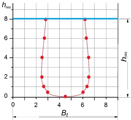
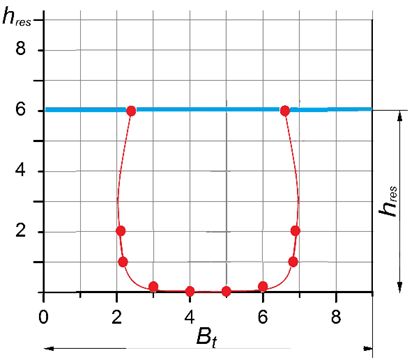
E3S Web of Conferences 264, 01020 (2021) https://doi.org/10.1051/e3sconf/202126401020
CONMECHYDRO - 2021

 Table 1. Parameters of nozzles
 Type Number of Dimensions of holes, Total area of Total perimeter
 holes mm holes S, mm2 of holes P, mm
 L b=d
 I 1 29.2 14.6 595 104
 II 2 20.6 10.3 595 147
 III 4 14.6 7.3 595 208.5
 IV 8 10.4 5.2 595 297

 To fix the size of the actively aerated zone, a Canon EOS M6 Mark II digital camera
 with a shooting rate of 14 frames per second was used.

 2.2 Experimental technique
 The experiments consisted of photographing the process of penetration of the gas-liquid jet
 into the thickness of the aerated liquid. The jet length in the air was 30 cm, and the
 reservoir width was 1.06 of the jet penetration depth.
 The liquid level changed sequentially. Initially, the liquid level was selected so that the
 gas-liquid jet was completely immersed without touching the bottom. Then the liquid level
 decreased, and the jet broke against the bottom of the reservoir, and air bubbles were
 distributed over the most significant part of the volume.
 For the experiment, the ratio between the thickness of the liquid layer hр and the depth
 of jet penetration hpen was chosen as the main factor affecting the size of the actively
 aerated zone. The experiment was conducted at the following levels of this factor
 hres /hpen 1.05 1 0.7 0.6 0.5

 The number of measurements at each level is the same and equals N=10. To process the
 experimental data and to test the null hypothesis on the substantial influence of the selected
 factor on the size of the actively aerated zone, a single-factor analysis of variance (a one-
 way ANOVA test) was performed.

 3 Results and discussion
 Analysis of variance of the experimental results made it possible to establish the degree of
 influence of the relative height of the liquid layer in the reservoir ht /hpen on the sizes of the
 actively aerated zone (the fraction of the reservoir volume in %, occupied by the spray
 pattern of gas bubbles). Analysis of variance results are presented in Table 2.
 Table 2. Results of analysis of variance
 Total mean Factorial Residual Fisher's variance Tabular value of Fisher's
 ̅ , % variance 2 variance 2 ratio fobser variance ratio ftab
 43.19 769.68 0.0972 7918.52 2.53

 Since fobser > ftab, the group means differ significantly. Consequently, we accept the null
 hypothesis about the significant effect of the height of the liquid layer relative to the jet
 penetration depth on the size of the actively aerated zone (and we reject the null hypothesis
 about the equality of group means).
 Experimental photographs were used to determine the sizes of the actively aerated zone
 for various ratios of the reservoir depth (the height of the liquid layer) and the jet
 penetration depth (Fig. 1). The dimensions in the figures are in relative units.

 4
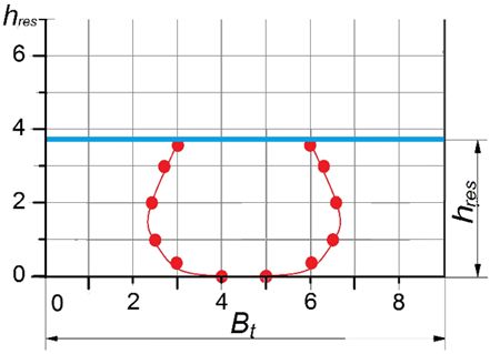
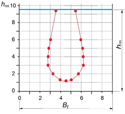
E3S Web of Conferences 264, 01020 (2021) https://doi.org/10.1051/e3sconf/202126401020
CONMECHYDRO - 2021

 a b

 c d
 a) hr /hpr =1.05, b) hr /hpr =1, c) hr /hpr =0.7, d) hr /hpr =0.5
 Fig.1. Shape of the aerated zone at different thickness of water layer in the reservoir (Bt – tank width,
 hres – reservoir depth (liquid layer))
 As seen from the graphs, a freely forming gas-liquid plume, when it fully immersed in a
 liquid (without depth restrictions), acquires a drop-like shape (Fig. 1, a), but with a decrease
 in the height of the water layer, it gradually approaches the shape of a cylinder (Figs. 1, b,
 c), and then the shape of a flattened drop (Fig. 1,d). The data obtained are consistent with
 other researchers [9] on the drop-like shape of a freely forming jet spray pattern.
 Considering that other authors have not studied the formation of a jet spray pattern when
 the height of the water layer is limited, there is no way to compare the other data we
 obtained.
 Experiments conducted with jets with different characteristics (velocity, flow rate,
 nozzle shape) made it possible to construct a generalized graph of dependence of the
 utilization factor of reservoir volume (with width 1.06 hpen) on the height of the liquid level,
 expressed in fractions of the total (possible) depth of penetration of the liquid jet (Fig. 2).

 5
E3S Web of Conferences 264, 01020 (2021) https://doi.org/10.1051/e3sconf/202126401020
CONMECHYDRO - 2021

 Fig.2. Graph of dependence of the share of the reservoir volume use on the ratio of the height of the
 water layer and the penetration depth
 Based on the results of the experiments, it can be concluded that for enterprises with a
 small amount of wastewater, where large areas of treatment facilities are not required, it is
 possible to carry out aeration in shallow reservoirs (the depth of the reservoir is (0.6 ...
 0.7)hpen). Table 3 shows the relationship between the spray pattern diameter and the jet
 penetration depth.
 Table 3. Relationship between the diameter of the gas-liquid plume dpl and
 the jet penetration depth hpen
 hres /hpen 1.05 1 0.7 0.6 0.5
 dpl /hpen 0.35 0.35 0.438 0.7 0.9

 From Figure 2 and Table 3 show that the most significant relative diameter of the spray
 pattern and the maximum utilization of the reservoir volume are at the ratio of
 hres/hpen=0.5...0.7. Consequently, for effective aeration of waste fluid in small facilities, it is
 necessary to select the depth of the reservoir so that the specified ratio is observed since, in
 this case, the gas-liquid jet breaks against the bottom of the reservoir and expands the
 aerated zone.
 The obtained data can be used in calculating the aerator with a certain liquid flow rate
 Qm3/day, at given biological oxygen demand (BOD) in incoming water L0 and purified
 water Lt, mg/l. The calculation is based on the determination of the oxygen transfer
 coefficient provided by the design of this aerator and in comparing this coefficient with the
 required KLa (20) in terms of the discharged liquid. Therefore, for the calculation, it is
 necessary to have data on the dependencies of the jet penetration depth hpen and the oxygen
 transfer coefficient on the liquid flow rate.
 Based on the results of our own research, as well as using the data of Shukla [22] using
 modeling in the Origin and Excel packages, an equation was obtained for the dependence of
 the required jet velocity on the depth of its penetration:

 6
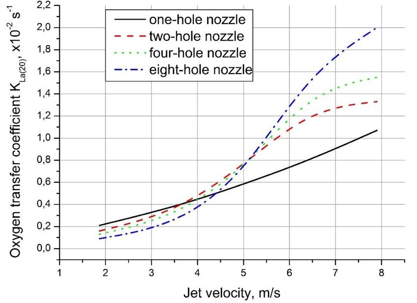
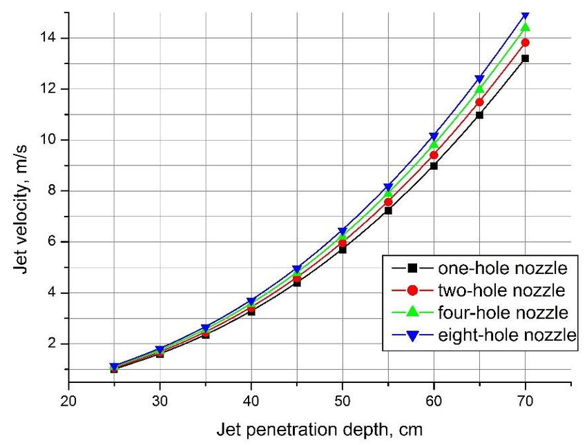
E3S Web of Conferences 264, 01020 (2021) https://doi.org/10.1051/e3sconf/202126401020
CONMECHYDRO - 2021

 1/2
 ℎ5

 = 0,0211 ( 0.775 ) (4)
 ⋅ 1.8

 Where n is the number of holes in the nozzle, P is the total perimeter of holes, mm
 Figures 3 and 4 show graphs of these dependencies for nozzles with a different number
 of "keyway" holes of a total area of 595 mm2.

 Fig.3. Graph of dependence of the jet penetration depth hpen on jet velocity

 Fig. 4. Graph of dependence of the oxygen transfer coefficient on jet velocity Based on the data
 obtained, the following algorithm for calculating the jet aeration plant is proposed.

 7
E3S Web of Conferences 264, 01020 (2021) https://doi.org/10.1051/e3sconf/202126401020
CONMECHYDRO - 2021

 The procedure for calculating the jet aerator
 Initial data: waste water consumption liquid Qww, m3/day; BOD of incoming wastewater
 L0, mg/l; required BOD of purified water Lt, mg/l.
 1. The number k of aerators with holes of the "keyway" type of a certain type is
 accepted (table 1)
 2. The jet penetration depth is set, hpen, cm
 3. The reservoir depth is set, hres = 0.7 hpen , cm
 4. Gas-liquid plume diameter is dpl = 0.438 hpen (Table 2)
 2
 ⅆ
 5. Gas-liquid plume cross-sectional area = , m2
 4
 6. The required surface area of the reservoir Fres = k∙F, m2
 7. Jet velocity v in the nozzle holes (formula (4), Fig. 3), m/s
 8. The required water flow rate through one nozzle, q1: q1=v∙S, m3/s
 9. The flow rate through k nozzles Q = q1∙k, m3/s
 10. Standard volumetric mass transfer coefficient KLa(20) is determined depending on q1
 (see graph in Figure 4)
 11. KLa(20) check
 a) the required amount of O2
 G = KLa (Cр – C)∙W

 where Cs is the solubility of oxygen in water (Cs = 9.1 mg/l at 20°C [26]),
 C is the average oxygen concentration in the treatment facility C=2 mg/l,
 W is the volume of the facility, m3
 b) on the other hand, the required amount of O2:
 G=z(L0-Lt) Qww

 z is the specific consumption of О2 of the removed BODtotal, mg/mg (z = 1.25 [26]),
 Qww is the rate of waste liquid, l/s (taken according to the initial data).
 c) required value of KLa(20)

 ( 0 − )
 (20) = ≥ (20) ′
 ( − ⅇ)

 (20) ′ is the value defined in item 10.
 If the condition (20) ≥ (20) ′ is not met, recalculation of the aerator is required
 using other options of the initial data (k, hpen).

 12. Aeration time is = ,s

 13. Pump selection is done by Q value (item 9)

 4 Conclusions
 The studies' results show that it is advisable to use jet aeration for biological treatment in
 small facilities. Experimental verification for a jet aerator with "keyway" holes showed that
 the sizes of the actively aerated zone depend on the ratio of the possible depth of the
 reservoir (the water layer thickness) and the possible penetration depth of the gas-liquid jet.

 8
E3S Web of Conferences 264, 01020 (2021) https://doi.org/10.1051/e3sconf/202126401020
CONMECHYDRO - 2021

 At that, it was determined that limiting the depth of the reservoir allows increasing the size
 of the aerated zone and the degree of utilization of the reservoir volume. With a decrease in
 the relative depth of the reservoir from 1.05 to 0.5 (2.1 times), the share of the beneficial
 use of the reservoir volume increases from 29.8% to 50% (1.68 times).
 The technique developed based on experimental data allows for a simple calculation of
 the jet aerator, which can accelerate the design processes of small treatment facilities.

 Reference
 1. Shapovalova L, Nurmatova V, Kirshina E, Smolkova O, Improved wastewater
 purification technology for villages in countryside of the Republic of Uzbekistan
 Proc. of the 19th Int. Conf. Sakharov readings 2019: environmental problems of the
 XXI century (Minsk) vol 3 (Minsk: ITC of the Ministry of Finance) pp 106-109.
 (2019)
 2. Muminova R and Kazimova N, The problem of wastewater treatment in Uzbekistan J.
 Young scientist 22 (102) pp 47-48, (2015)
 3. Serpokrylov N, Smolyanichenko A and Lesnikov I, Comparative analysis of aerators
 for wastewater purification and unified aeration criteria J. SGASU Bulletin. Urban
 planning and architecture 2 pp 97-100. (2011)
 4. Gogina E and Makisha N, Reconstruction of wastewater treatment plants in Russia,
 approaches and solutions. J. Applied Mechanics and Materials vol 361–363 pp 628–
 631 (2013)
 5. Itano T, Inagaki C, Hashimoto R, Negoro N, Hyodo J and Honda S. Water circulation
 induced by mechanical aerators in a rectangular vessel for shrimp aquaculture J.
 Aquacultural Eng. 85 pp 106–113 (2019).
 6. Xiangju C, Jun X, Deguang Y and Yingxue Z, Calculated analysis of oxygen transfer
 from air bubble-water interface and turbulent water surface in microporous aeration
 systems. Transactions of the Chin. Society of Agric. Eng. (29) 13 pp 190–199. (2012)
 7. Abdukodirova M and Radkevich M, Opportunities for application of jet aerators in
 biological cleaning facilities J. Universum: Techn.Sci. 5 (74) Part 1 pp 60-63, (2020)
 8. Orekhov G, Flow characteristics and peculiarities of cavitation phenomena in
 counter-vortex flow energy dissipators of hydraulic structures. The Eurasian Scientific
 Journal 3 (11), (2019 )
 9. Samokhvalova A, Kuksova A and Yurchenko V, The main types of jet aerators used
 in wastewater treatment J. Naukoviy visnik budivnistva (Scient. Bul. of the Buil.) 3
 pp 124-128. (2015).
 10. Lobov W, Sugak A and Gontscharov G, Die Bewegungstraiektorie einer Gasblase im
 stark durchlüfteten Bereich von Strahlapparaten mit unterschiedlich geformten
 Düsen. Technische Fachhochschule Wildau. Wissenschaftliche Beiträge 1 pp 159-162
 (2000)
 11. Cummings P and Chanson H. Air entrainment in the developing flow region of
 plunging jets – Part 1: Theoretical Development J. of Fluids Eng. 119 pp. 597-602.
 (1997)
 12. Bouvard J, B'eguin C, Etienne S, Scott D and Bornard L, Characterization of bubble
 cloud quality and evolution using optical probes. Proc. of the 29th IAHR Symposium
 on Hydraulic Machinery and Systems IOP Conf. Ser.: Earth Environ. Sci. 240
 062051 (2019).
 13. Lima Neto I E, Zhu D Z and Rajaratnam N, Air Injection in Water with Different
 Nozzles. J. Environ. Eng. 4 (134) pp 283–294. (2008).
 14. Lima D D and Lima Neto I E, Effect of nozzle design on bubbly jet entrainment and
 oxygen transfer efficiency J. Hydr. Eng. 8. (144). (2018)

 9
E3S Web of Conferences 264, 01020 (2021) https://doi.org/10.1051/e3sconf/202126401020
CONMECHYDRO - 2021

 15. Ledyan Yu P, Selivonchik B B and Shcherbakova M K, The use of jet aeration to
 improve the efficiency of water purification in the recirculating water supply system of
 the foundry Casting and metallurgy 4 (49) pp 161-164. (2008).
 16. Ledyan Yu P and Selivonchik B B Application of jet aeration to intensify the flotation
 process. Bulletin of BNTU 6 pp 52-55. (2008)
 17. Inventor's certificate 798051 (USSR). Method of liquid aeration (N.F.
 Meshcheryakov, Yu.V. Ryabov, M.A. Podvigin, M.A.Gamilov). Publ. in BI, (3)
 (1981)
 18. Kusabiraki D, Niki H, Yamagiwa K and Ohkawa A, Gas entrainment rate and flow
 pattern of vertikal plunging liguid jets The Can. J. Chem. Eng. 68 (6) pp 893 – 903,
 (1990).
 19. Van de Sande E and Smith Y.M, Set break-up and air entrainment by low velocity
 turbulent water jets Chem. Eng. Sci. 31. pp 219-224. (1976).
 20. Safronova E V, Spiridonov A V and Mitinov A V, Design and calculation of effective
 jet devices for the "liquid-gas" system Bull. of Polotsk State University 6 pp 190-194,
 (2016).
 21. Abaev G N and Chernyavskaya E V, Patterns of hydrodynamics and mass transfer in
 jet device. Eng. Phys. J. 74 (3) pp 184 – 188. (2001).
 22. Shukla B K and Goel A, Study on oxygen transfer by solid jet aerator with multiple
 openings. Eng. Sci. and Techn., an Int. J. 21 pp 255–260. (2018).
 23. Suciu G and Smigelschi O, Size of submerged biphase region in plunging jet systems
 Chem. Eng. Sci. 31 (12) pp 217- 220. (1976).
 24. McKeogh E Y and Ervine D A, Air entrainment rate and diffusion pattern of plunging
 liquid jets Chem. Eng. Sci. 36 (7) pp 1161-72. (1981).
 25. Roy A. K., Maiti B. and Das P.K. Visualization of Air Entrainment by a Plunging Jet.
 2013 Procedia Engineering 56, pp 468–473. DOI: 10.1016/j.proeng.2013.03.148.
 (2013).
 26. Guidelines for determining the need for electrical energy for technological needs in
 the field of water supply, sewerage and wastewater treatment 2007, (Moscow: Center
 for Municipal Economy and Law) p 16. (2007).

 10
You can also read