SOCIALLY DISTANCED ROBOTICS ROBOBOAT 2021 - GEORGIA TECH
←
→
Page content transcription
If your browser does not render page correctly, please read the page content below
GEORGIA TECH MARINE ROBOTICS GROUP                                                                  1

                    Socially Distanced Robotics
                   RoboBoat 2021 - Georgia Tech
Tyler Campbell, Justin Chau, Yash Chitale, Luke Dorrian, Sean Fish, Daniel Foreman,
    Eric Fu, Ali Kazmi, Chenxuan Li, Jeffrey Pattison, Hannah Payne, Eric Phan,
   Coline Ramee, Rahul Rameshbabu, Tristan Sarton Du Jonchay, Saahas Yechuri

   Abstract—For many disciplines and indus-         health and safety of our team, ASV2020 is still
tries, remote collaboration has become a neces-     awaiting final assembly and its maiden voyage.
sity during the COVID-19 pandemic. Likewise,            In the case RoboBoat 2021 had been held in
the Marine Robotics Group at Georgia Tech           person this year, the team would have prioritized
has adapted to the current situation through        completing construction in late spring and early
the use of online tools. This paper details         summer, as vaccines became available. The new
developments in our vehicles, electronics, and      boat would have utilized the existing Adept soft-
design process made in preparation for the          ware stack which has been tested in past compe-
2021 RoboBoat competition and other activ-          titions.
ities. While our access to campus facilities
was limited, a new autonomous surface ve-
hicle (ASV) was constructed without the use
of advanced manufacturing methods, and a
new hydrophone system prototype was built.
Our Unmanned Aerial Vehicle (UAV) system
received upgrades to its navigational capabil-
ities. A new method of live collaboration for
software development was created, allowing for
members to develop without needing to install
the full development environment.

                                                           Figure 1: Simulation of ASV2020.
            I. C OMPETITION S TRATEGY
    Prior to the start of lockdowns, the team had     While our in-person activities were hindered
been preparing for the RoboBoat 2020 compe-         by the circumstances, we took advantage of this
tition with the development and construction of     opportunity to focus on other aspects of design
a newly designed autonomous surface vehicle,        and collaboration.
hereafter referred to as ASV2020 [1]. This new
vessel was designed with new pontoons featur-
ing improved hydrodynamic qualities and durable     A. Design
dual layered fiberglass. The foam structures of        With the distance separating our members, we
the pontoons had been manufactured prior to the     focused on parallel development of new hardware
pandemic, but the fiberglass process had not been   systems. Each project involved the development
completed. Unfortunately, due to limitations im-    of a prototype, with each built by an independent
posed by the lockdown and concern for personal      member. This way, development of a system could
GEORGIA TECH MARINE ROBOTICS GROUP 2
progress, with the hope that future iterative im- simulation. Through the use of the Virtual RobotX
provements could be made as a team when we (VRX) simulation environment [2], we have been
are able to interact in person. able to test ideas without the need to go to
1) Autonomous Surface Vehicle: This year, a a physical testing location. Further, a model of
new autonomous surface vehicle was developed ASV2020 has been created through the adaptation
separately from the existing ASV2020 project. of the VRX simulation to enable testing specific
This new ASV, known as the Measure Once Cut to the vehicle.
Twice (MOCT), was assembled with the purpose
of testing new ideas on a smaller and simpler II. D ESIGN C REATIVITY
testbed. This vessel is not intended to serve as a This year, many of our innovations were made
competition vessel, but rather a supporting vehicle on individual components, as our work on hard-
to facilitate iterative development and provide a ware was focused on developing independent pro-
teaching platform. totypes. In addition to this, changes at an or-
2) Hydrophone: Significant progress was made ganizational level have provided a new way to
in the design of a hydrophone system developed collaborate on software development.
in-house. Research into necessary hardware and
filtering has informed our component selection,
and a prototype is in development. This hy- A. Autonomous Surface Vehicle
drophone system will enable our team to be able
to localize pingers in the RoboBoat competition
environment, as well as in other competitions.
The knowledge gained in building a sensor system
from the ground up will be helpful as we seek to
build other in-house modules as well.
3) Unmanned Aerial Vehicle: The UAV under-
went considerable development during the past
year. Autonomous navigation was implemented,
and the addition of further capabilities such as
transportation of objects is planned. The creation
of a companion system will further increase the
potential of our system in the RoboBoat competi-
tion, specifically for tasks relating to transporting
objects, and will also have potential uses in the
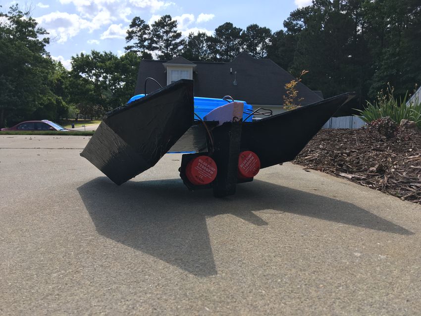
upcoming RobotX competition. Figure 2: Front view of catamaran, with thrusters.
The Measure Once Cut Twice was constructed
B. Collaboration off campus, without access to advanced manu-
This year, we have faced the challenge of on- facturing methods such as 3D printing, CNCs,
boarding new members without face-to-face in- or laser cutters. It was designed to minimize
teraction and without access to the machines or cost, size, and complexity in construction, and to
dedicated computer hardware. Another challenge facilitate easy testing and transportation, as the
we have had during this period of remote work vessel is able to easily fit into the passenger seat of
is lost knowledge, as many of our integral team a car. Building MOCT also provided a test of new
members have graduated. To solve these issues, construction methods and materials. With a rather
we have been utilizing collaboration software. small displacement of around 15lb, it is designed
Our collaboration method leverages another to only carry a light computer and a few small
component of our strategy, which is the use of sensors.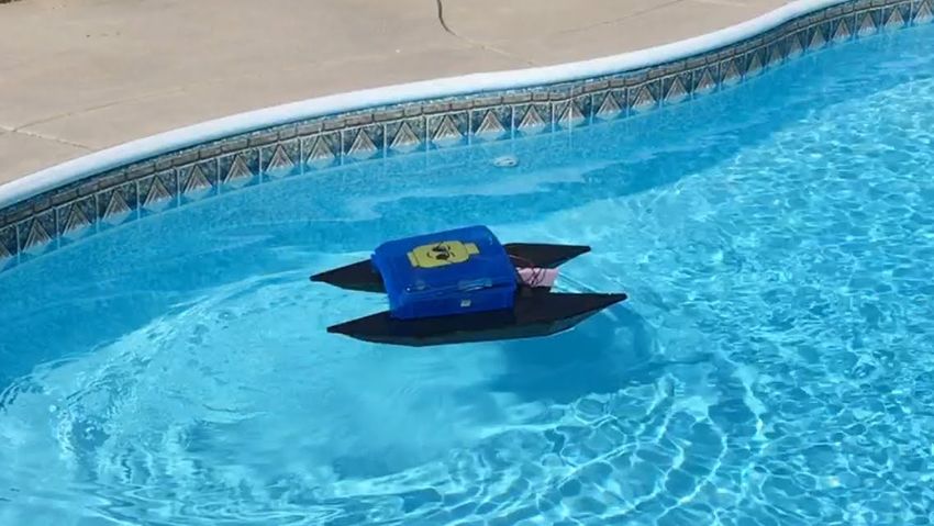
GEORGIA TECH MARINE ROBOTICS GROUP                                                                       3

   The hull of the new ASV is a catamaran design,       Additionally, the hydrophone team wished to have
providing stability like our previous ASVs [3], but     a portable solution that could be used not only
differs greatly in its assembly. It is one piece,       on this boat, but on other vehicles such as our
constructed from a used Tri-fold Foam Display           RoboSub and WAM-V. For this reason, the best
Board (28” x 40”) which was scored and folded           solution was deemed to be an external, watertight,
into the shape of a boat. This hull was then given a    housing for the hydrophone circuitry. Due to the
coating of rubber using Flex Seal Liquid, while the     pandemic, work on this enclosure has yet to begin.
structure was held in place using pins and packing         2) Electrical Design: After researching com-
tape.                                                   mercial and other RoboBoat teams’ hydrophone
   The boat is equipped with two thrusters con-         solutions [5], we identified multiple requirements
structed from converted bilge pumps, as is com-         for the hydrophone electronics. A steady voltage
mon in home-made ROVs [4]. These thrusters are          source, as well as electronic decoupling from
mounted on a construction of Owens Corning pink         other onboard electronics was critical to ensure
foam and foamboard, with the thrusters located          the hydrophones’ circuitry did not experience
close to the center of mass as to facilitate turns      transient electronic ripple, which would make
while minimizing motion using differential thrust       readings unreliable. Capacitor-based filters and a
control. This differs from the holonomic thruster       variety of voltage-regulator designs were identi-
configuration [1] to be implemented on ASV2020,         fied as possible solutions. Hydrophones, for this
but still provides a simple, if somewhat noisy,         application, ideally would have a uniform gain
control layout.                                         distribution. The RESON TC 4013, which had
   While design and assembly took place over sev-       been procured in prior years, satisfied this re-
eral semesters, the actual time spent constructing      quirement. Transduced hydrophone signals would
the boat was about a day with just one person.          be highly transient and of low-voltage, making
All materials excluding the electronics can be          them susceptible to external interference and loss
sourced from local stores such as Walmart and           during the signal transmission and Analog to
Home Depot. Since the liquid rubber can cure in         Digital (ADC) sampling processes. To combat
24 hours, it is possible for the hull to be completed   this, an op-amp solution was formulated that
within two days, in case a vehicle needs to be          would amplify the hydrohone signal, and re-bias
rapidly constructed.                                    the signal to be centered in the ADC’s mea-
                                                        surement range. Additionally, with the relatively
                                                        high bandwidth of the hydrophones and ampli-
B. Hydrophone                                           fier, spurious noise was expected. As the design
   This year, there was significant progress made       was already actively amplified, an active band-
in the design of an in-house hydrophone system.         pass filter was conceived to perform pre-filtering
Cumulatively, the hydrophone system incorpo-            on the hydrophone data, passing through signals
rated multiple engineering disciplines: Mechanical      between 30-45KHz, the expected frequency of the
design to create a watertight external housing,         acoustic beacon. Although this general design was
Electrical to design and fabricate a Printed Cir-       conceived in the 2020 competition year, in the
cuit Board (PCB) with the required signal pre-          2021 competition year, many of the numerous
processing and connectivity, and Computer Sci-          unknowns were fleshed out in the design, although
ence to perfect the signal processing algorithms.       the exact circuitry has not been decided upon at
   1) Mechanical Design: Hydrophone circuitry           this time. For sampling and data-processing, the
is notoriously sensitive to environmental noise,        STM32 NUCLEO-H745ZI-Q board was chosen
and in past attempts, directly connecting them to       for its 16-bit, 3-channel SAR ADC that could
voltage sources shared by even something like           handle external voltage references and sample at
an Arduino board sending Pulse-Width modulated          3.6 Megasamples-per-second (Msps). The STM32
signals has caused severe measurement issues.           board is well-supported and documented, and its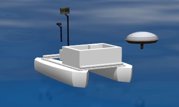
GEORGIA TECH MARINE ROBOTICS GROUP                                                                       4

built-in ADC simplified the circuitry design for      ences to be accurately found for non-sinusoidal
the hydrophone board. External references would       signals, and for noise-floor considerations to have
allow the board to accept the same voltage used       less of an impact on the calculated solution.
by the amplification and pre-processing circuitry,
and eliminate biases that would otherwise be
accrued if the two electronic systems were in-        C. Unmanned Aerial Vehicle
dependently generating voltage references. The           One task for this year’s RoboBoat competition
Megasampling rate was critical to ensure proper       was to deliver up to four objects to the delivery
data collection. Reviewing sampling solutions         dock. To complete this task, the payload could
from other RoboBoat teams, hydrophones were           either be delivered using the ASV or a UAV. In
typically sampled at rates between 500Ksps to         order to achieve this goal, the Georgia Tech Ma-
42Msps. In prior attempts to sample hydrophone        rine Robotics Group decided to design and build
data, 110Ksps was used to sample a signal at          a UAV to deliver the payload. The UAV would
45KHz, and although it was above the Nyquist          launch from the ASV and then fly autonomously
frequency for the data, performed very poorly in      to the delivery dock location to drop the payload.
capturing the signal. To prevent this from happen-       1) Vehicle Design: When designing a UAV,
ing again, a sampling rate in the Msps was very       the first design consideration is to decide what
desirable.                                            the UAV needs to accomplish. First Person View
   3) Algorithm Design: In 2020, the hydrophone       (FPV) racing UAVs have a much different design
algorithm attempted to directly measure the time      than UAVs used for delivery. The FPV UAVs have
of arrival of a sinusoidal hydrophone signal, and     smaller frames with faster motors and are designed
use 3 times of arrival to perform 2D multilatera-     for agility and speed, while the delivery UAVs
tion. However, this design had multiple problems.     utilize larger frames and slower motors to trade
Due to multipathing and signal corruption, the        agility and speed for stability and the ability to
sinsoidal signal emitted by an acoustic beacon        lift heavier payloads. With this in mind, a 450
was not actually sinusoidal when it was received      mm quadrotor frame was chosen. On this larger
by the hydrophones. Secondly, there is frequently     frame size, 12 inch propellers can fit to provide
ambiguity in when the signal was received due to      plenty of lift while also having enough space for
a noise-floor in the measurements. The multilater-    all the required electronics and payload. After
ation formulas are highly sensitive to ambiguity in   deciding the frame, the next step was to design
arrival time, especially when the acoustic source     the power train of the UAV, consisting of the
is located a far distance from the hydrophones,       battery, ESCs, and motors. The motors need to be
compounding the problem. To combat these prob-        selected based on the lift they can produce to lift
lems, a differenced version of the multilateration    the weight of the UAV, but at this point the weight
algorithms was used, transforming them from           of the UAV is unknown so the thrust required
a parabolic to hyperbolic form. This technique,       is unknown. To circumvent this conundrum, an
which appears to be the standard approach to          estimation of the final weight of the UAV was
problems such as this, addresses both of the          created to start selecting which motors to use. The
above problems when used in conjunction with          estimated weight of the UAV was constructed by
correlations between hydrophone time-series. By       combining the weight of the frame, approximate
repeatedly calculating element-wise correlations      weight of four ESCs, approximate weight of four
between recorded hydrophone time-series, each         motors, the flight controller, flight computer, GPS,
repetition shifting the points to be correlated by    battery, payload, and landing gear. The weights
some time delta, the best estimate for time of        of the motors and ESCs were approximated due
arrival difference could be found by selecting the    to not having a specific motor chosen. The final
time delta corresponding to the maximum corre-        UAV weight estimate was a conservative 7 lbs.
lation. This selection process allowed time differ-   With this initial estimate, the RCTimer HP2814
GEORGIA TECH MARINE ROBOTICS GROUP                                                                        5

810 Kv motors were chosen because they produce          UAV since it will need to lift a payload. With the
over 2kg of thrust per motor with a 4 cell LiPo         weight and power train, the estimated flight time
battery and 12 inch propellers. A lower Kv rating       was 12 minutes, which is more than would be
was chosen for the motors since larger propellers       required in the competition to deliver the payload
were used, and the rotor/stator size were selected      to the delivery dock.
due to the high torque to easily turn the larger
propellers. For UAVs, the thrust to weight ratio
should be over 2 to ensure good controllability of
the UAV, and this initial thrust to weight ratio is
approximately 2.5.
   With a 4 cell LiPo battery, the motors selected
can pull up to 23 amps per motor. The ESCs
and battery need to be able to handle this strain.
In order to handle the current required for each
motor, four 30 amp ESCs were selected. The
battery also needed to be able to handle the current
output of four motors potentially pulling 23 amps
each, plus the onboard electronics required. The
battery selected was a 5000mAh 4 cell LiPo
battery with 35C rating, which allows the battery
to discharge almost 170 amps. This battery is                   Figure 3: UAV during test flight.
more than enough to handle the demand of the
electronics and motors.                                    2) Mission Planning and Mission Execution:
   With the power train designed, the flight con-       While a mission plan was created, the actual
troller needed to be selected. A Pixhawk with           development and implementation of the required
Ardupilot was selected due prior experience work-       programming for mission execution was not com-
ing with the equipment. Connected to the flight         pleted, but below is an outline of how it would
controller was a GPS that had accuracy within 3         have been done. After examining the course, the
meters. The combination of GPS with the Pixhawk         best time for the UAV to launch would be when
flight controller allowed for autonomous GPS            the ASV was at the acoustic docking station. This
waypoint following. The Pixhawk flight controller       point in the course is next to the delivery dock
allowed for lower level control and stability, but      so the UAV would not have to fly far. The ASV
a flight computer was required to do higher level       can SSH into the Raspberry Pi to run a Python
computation like image classification and mission       script to begin the UAV mission. DroneKit is a
execution. A Raspberry Pi 4 with 2GB of RAM             Python package that allows the Raspberry Pi to
was selected as the companion computer since it         communicate with the Pixhawk flight controller to
was easy to integrate with the Pixhawk.                 send commands. The ASV would then command
   The final configuration of the UAV consisted of      the Raspberry Pi to launch this mission script. The
the 450 mm frame with 4 motors turning 4 12 inch        mission script would contain other functions in-
propellers powered by a 4 cell LiPo battery and         cluding Takeoff, Scan, Land, Deliver, and Return
driven by a Pixhawk flight controller connected to      to Home. The Takeoff function would run first to
a Rasbperry Pi companion computer. A downward           get the UAV to launch to a given altitude.
facing camera was added to be able to find the             After launching, the UAV would then begin
delivery dock. The final weight without payload         flying in the general direction of the delivery
was found to be 5 lbs, which is below the initial       dock in the Scan segment of the mission. Using a
estimate of 7 lbs. With this final weight, the thrust   Raspberry Pi camera on the UAV with an image
to weight ratio is 3.52, which is sufficient for the    classifier on the Raspberry Pi, the pattern of the
GEORGIA TECH MARINE ROBOTICS GROUP                                                                          6

delivery dock could be recognized and used as         but failed to converge on a solution, and was
a target for the UAV and a trigger to begin           ultimately discarded. In 2021, a second attempt
the descent and drop off. Again, the DroneKit         was made to perform Kalman filtering. To pro-
package would use the image from the Raspberry        totype this filter, the filter was first applied in
Pi camera with OpenCV [6] to update the UAV           simulation in the VRX WAM-V Gazebo simulator.
on where to go to get the dock directly below the     An Extended Kalman Filter (EKF) was chosen, as
UAV, and the Raspberry Pi would then send the         it would perform better than a standard Kalman
commands to the Pixhawk. After the delivery dock      Filter under nonlinearities in the estimated sys-
was located and centered under the UAV, the UAV       tem. The filter estimated x-y planar position and
would then begin the Land and Deliver portion of      yaw, as well as their first and second derivatives.
the mission.                                          Updates to thruster commands and IMU and GPS
   Unfortunately, the UAV was not developed           measurements were used to perform correction
enough to have a release mechanism for the pay-       updates to the estimated state. GPS latitude, lon-
load just yet. However, the plan was to add a servo   gitude and height were converted into a delta x
motor powered from the Pixhawk to carry a net         and y from the boat’s starting point. IMU data
that could contain the payload. Upon landing on       was handled raw. Thruster commands, ranging
the delivery dock, the servo would turn to release    between -1 and 1, were converted into expected
the net from the drone, completing the delivery.      thrust forces and moments using knowledge of the
Upon completing the delivery, the UAV would           simulated model’s geometry and corresponding
enter into the Return to Home function, where the     calculated mass properties. For additional realism,
UAV returns to the predetermined Home on shore        the model had the optional ability to account
instead of trying to return to the ASV. The Return    for viscous damping constants in each of the 3
to Home segment is enabled by the Pixhawk with        principal directions. The filter could predict future
the ability to fly to a GPS waypoint and land, thus   propagated states under its model, as well as gen-
completing the mission.                               erate its internal Jacobian via analytical derivation
                                                      or numerical differencing.
D. Software                                              The 2021 Kalman filter showed some promise
                                                      of potentially replacing the current navigation
   We are still utilizing the Adept software stack
                                                      algorithm, a GPS-only exponential filter, as it was
that has been in development for the past few
                                                      shown to be able to blend GPS, IMU, and thruster
years, and have been working with this stack in
                                                      updates into its estimation. This represented a step
simulation. However, this pandemic has provided
                                                      forward, as earlier attempts had rapidly diverged
us the opportunity to start porting our system
                                                      due to instabilities inherent to their state transition
from ROS1 to ROS2, as the gap in competitions
                                                      matrices. While the 2021 filter still would diverge,
gives us more time to solve various issues that
                                                      especially when estimating viscous drag, it had the
may arise. One area of development was improved
                                                      ability to perform state estimation while maneu-
navigation through the use of a Kalman Filter.
                                                      vering the simulated WAMV moving at full speed.
                                                         Currently, the 2021 Kalman filter needs im-
E. Kalman Filter                                      provements before it can be a true replacement
   In years past, GT RoboBoat has attempted to        for the existing navigation solution. Its instability
improve its navigation system with a Kalman filter    is a critical issue, and is worsened by a missing
to blend IMU and GPS measurements. This was           knowledge of thrust forces, observed impreci-
motivated by sporadic GPS measurements during         sions during matrix inversions and a numerically-
competitions, which paralyzed the GPS-exclusive       sensitive formulation of drag force. Additionally,
navigation system, as well as a general desire        the rate information from the IMU appears to
to improve state estimation for the boat. In the      warrant further investigation, as it appears that the
spring of 2020, a Kalman filter was implemented,      observed velocities have the right sign, but are far
GEORGIA TECH MARINE ROBOTICS GROUP 7
too small compared to a ground truth, indicating frequency is too high, causing the motor driver to
a possible timing issue within the filter. When overheat. A future test will confirm if this was the
compared against the exponential GPS filter for issue.
positioning, the Kalman filter was found to have
more error, possibly owing to the rate information
B. Hydrophone
not being properly passed and interfering with
positioning estimation. Further investigation and To test the efficacy of a differenced version of
tuning will be needed to improve the accuracy of the multilateration algorithms, a prototype algo-
the RoboBoat’s navigation system. rithm was created in MATLAB and applied to
data collected four years ago using 2 hydrophones
III. E XPERIMENTAL R ESULTS and an acoustic beacon. As 3 hydrophones are
needed to fully constrain and identify a unique
The main software stack was tested in the VRX planar solution, the multilateration formulas were
simulation. Through observation of the perfor- modified to assume parallel incident rays being
mance of the vehicle in VRX, the team deter- received by both hydrophones. Correlation was
mined potential areas of improvement. Further, used to identify the time difference between hy-
parameters of the dynamic model of the ASV2020 drophone measurements, and the result was used
simulation were adjusted by trial and error to to identify the heading of the acoustic beacon
better simulate realistic performance. relative to the perpendicular bisector of the two
As our team was unable to meet in person, hydrophones. The results appear promising, as
physical tests have largely been limited to inde- they match up nearly identically with the heading
pendent systems. that was identified by the original test-operators.
Figure 4: View of catamaran, in pool.
A. Autonomous Surface Vehicle
A pool test for the MOCT vehicle gave valuable
insight into the performance of the new thrusters.
The new thrusters use brushed DC motors unlike
our usual Blue Robotics thrusters, so the method
of powering and controlling these motors was new
and involved the use of a dual H-bridge motor Figure 5: Testing hydrophone circuitry.
driver. In the test, the thrusters were only able to
sustain propulsion for several seconds at a time. In addition to this, tests of the actual hy-
It is suspected at this time that the current PWM drophone were made using an oscilloscope, andGEORGIA TECH MARINE ROBOTICS GROUP 8
successfully demonstrated that the presence of the IV. C ONCLUSION
pinger could be detected using our sensors. Though this past year has been unexpected and
challenging, we are excited to apply the new skills
C. Unmanned Aerial Vehicle and knowledge we have gained. We have been
able to construct component systems that will be
The UAV system was tested several times. integral to our future efforts, and have been able
While there were some initial issues with con- to improve our collaborative capabilities as an
troller settings, these were subsequently resolved. organization. With a return to full in-person efforts
The UAV succesfully demonstrated a flight, main- this upcoming fall semester, the team will be able
taining a defined altitude , navigating to a specified to start off strong with the developments made
GPS coordinate, and then landing. and lessons learned in preparation for this year’s
competition.
D. Collaboration
V. ACKNOWLEDGEMENTS
This past academic year marks the first time
we started leveraging live collaboration in our de- This team’s activities are made possible by
velopment process. Through the use of programs the generous contributions from Georgia Tech’s
such as BlueJeans video conferencing software Aerospace Systems Design Lab, Student Gov-
and the LiveShare extension for Visual Studio ernment Association, and School of Aerospace
Code, we were able to develop interactively. This Engineering Student Advisory Council. Our group
provided advantages such as rapid iteration in is also supported by our sponsors: Fischer Con-
software prototyping and reducing the need to nectors, Greenzie, ConnectTech Inc., and Pattent.
resolve merge conflicts. This method was first Our team thanks them for their support! Further,
utilized in the Virtual Ocean Robotics Challenge we would like to acknowledge the former and
[2], where we created a new software stack from current members of the Marine Robotics Group
scratch in a week that performed reasonably well. whose work forms the basis of all of our activities.
This spring, we began using this live collabo- To those who have graduated and are graduating
ration process for onboarding, to get around the during this time, we will miss you!
difficulties of installing ROS and Linux on new
members’ machines. This method proved to be VI. R EFERENCES
quite effective in providing a crash course on the R EFERENCES
software stack and framework we use. However, [1] A. Kazmi, A. Sinha, A. Velte, C. Ramee, D. Foreman, D. Di-
there were limitations to this technique that we Carlo, E. Jahoda, E. Fu, E. Phan, J. Pattison, J. Adrande,
still need to overcome. One issue was that work J. Chau, L. Dorrian, M. Schlaff, M. C. Martin, M. Gilmartin,
P. Meyer, P. Eddu, R. Rameshbabu, R. Kuramshin, R. Vepa,
could only be done when the host computer was S. Fish, T. Daino, T. Campbell, and V. Chow, “Roboboat 2020:
active, thus making all work simultaneous, which Technical design review,”
is good for tutorials but not for entire projects. Due [2] B. Bingham, C. Aguero, M. McCarrin, J. Klamo, J. Malia,
K. Allen, T. Lum, M. Rawson, and R. Waqar, “Toward
to this, it was still required for members to install maritime robotic simulation in gazebo,” in Proceedings of
a local Linux and ROS environment on their own MTS/IEEE OCEANS Conference, (Seattle, WA), October
computers once the tutorial portion of the semester 2019.
was over, nullifying the original advantage in the [3] V. Ruia, J. Chen, H. Chen, A. Spalding, A. Joshi, L. Arsene,
and S. Seifert, “Hall and boats: Roboboat 2017 - georgia tech,”
long run. This technique is great for collaborative [4] S. Thone, “Converting a bilge pump to run a propeller.”
coding sprints, but is not sustainable for long [5] R. Summers, “Hydrophone development.”
term projects. As new software such as Windows [6] G. Bradski, “The OpenCV Library,” Dr. Dobb’s Journal of
Software Tools, 2000.
Subsystem for Linux 2 are updated, we hope to
further reduce the difficulties of installing robotics
development environments.GEORGIA TECH MARINE ROBOTICS GROUP 9
VII. A PPENDIX A - C OMPONENT S PECIFICATIONS
Component Vendor Model/Type Specs Cost Status
MOCT Hull In-house N/A 40” length, ∼15 lb max $20 Testing
displacement
MOCT Thruster Sanuke Bilge Pump - 12V 1100gph $20 Testing
Heavily modified
MOCT Motor driver TIMESETL L298N Driver Double H-bridge, 5V-35V, $3 Testing
2A max
MOCT Spektrum AR610 Receiver 6ch 2.4GHz DSM2/DSMX $40 Testing
Teleoperation
MOCT Computer Raspberry Pi Model 3B 1GB RAM $49 Not
Integrated
MOCT Battery Zippy Compact LiPo 11.1V 3s 1300mAh $12 Testing
Hydrophones Teledyne Marine Reson TC 4013 http://www. Unknown Testing
teledynemarine.com/
reson-tc4013
Hydrophone proces- STMicroelectronics STM32 https://www.st.com/ $29 Development
sor NUCLEO- en/evaluation-tools/
H745ZI-Q nucleo-h745zi-q.html
UAV Platform Uncertain 450mm 450mm frame ∼$20 Testing
UAV Battery Tattu LiPo 14.8V 4s 5200mAh $61 Testing
UAV Motor Rctimer HP2814 710KV $20 Testing
Brushless Motor
UAV Receiver Turnigy iA6C PPM/SBUS 8ch 2.4GHz $11 Testing
Receiver
UAV Propeller QWinOut Carbon Fiber CW/CCW 1245 $31 Testing
Propellers
UAV Flight Con- Pixhawk 2.4.8 https://docs.px4.io/master/ $65 Testing
troller en/flight controller/
pixhawk.html
UAV Companion Raspberry Pi Model 4B 2GB RAM $35 Testing
Computer
Algorithms In-house
Vision OpenCV and In-
house
Acoustics In-house
Localization and In-house
mapping
Autonomy In-house
Team Size (number 16
of people)
Expertise ratio 1:3
(hardware vs.
software)
Testing time: simu- 10+ hours
lation
Testing time: in- 1 hour
water
Inter-vehicle WIP
communication
Programming Lan- Python, MATLAB,
guage(s) C++You can also read