DESIGN AND ENVIRONMENTAL TESTING OF THE DFKI-X ROBOTICS JOINT FOR SPACE APPLICATIONS
←
→
Page content transcription
If your browser does not render page correctly, please read the page content below
DESIGN AND ENVIRONMENTAL TESTING OF THE DFKI-X ROBOTICS JOINT FOR
SPACE APPLICATIONS
Niklas. A. Mulsow, Roland U. Sonsalla, Patrick Schöberl, Tobias Stark, and Frank Kirchner
DFKI Robotics Innovation Center, Robert-Hooke-Str. 1, 28359 Bremen, Germany
Email: {niklas.mulsow, roland.sonsalla, patrick.schoeberl, tobias.stark, frank.kirchner}@dfki.de
ABSTRACT
Within this paper we present the electro-mechanical de-
velopment and testing of a highly integrated robotic joint.
We are giving insight in the design of mechanical and
electrical components and their evaluation with respect
to a LEO mission. Furthermore, the model philosophy is
described to adapt a joint, originally developed for terres-
trial robots, to space qualification. The result is a novel
and compact motor unit with integrated control electron-
ics for space applications.
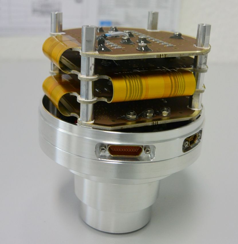
Key words: Robotic Joint, Space Actuator, Driving Unit, Figure 1. Electronics comparison: left EQM, right DM
Driver Electronic, New Space.
the joint, the development model (DM) was significantly
1. INTRODUCTION reduced in size (see Fig. 1) and different approaches for
stacking individual functional blocks of the electronics
Future space missions show an increasing need for mul- were investigated. For evaluation, a structural-thermal
tipurpose, modular, but still compact and performant, ac- model (STM) of the motor electronics was built and used
tuation units. Past and current missions are using a wide during mechanical loads and thermal testing.
variety of actuators. Typically, actuators and the asso-
ciated control systems are mostly developed as separate The qualification of the joint, including relevant en-
elements for a specific use case. To reduce mission and vironmental tests according to a LEO mission is de-
development costs and to increase the actual short-term scribed. A two-phase model and test philosophy was
availability of actuator units for space applications, need chosen, while the tests were in dependence on the ECSS
arises for a highly integrated and performant robotic joint. standards. Qualification included thermal-cycling and
The DFKI-X joints approach is promising to meet these thermal-vacuum, mechanical loads, including random
demands and also to be beneficial for upcoming New and sine vibration, EMC as well as radiation tests with to-
Space applications. tal ionizing dose and neutron irradiation. While tests have
been successfully passed according to the focus of design
Based on previous research [1], the further development and the LEO reference mission, different shortcomings
of the DFKI-X joints motor-gear unit, motor electronics and deficiencies could be observed during extended ex-
and control software is specified. The joint encompasses perimental tests. Besides the presentation of the robotic
a torque optimized brushless DC motor in combination joint’s design, results from qualification tests and lessons
with a harmonic drive gearbox. To reach a high level of learned are discussed within the paper.
compactness hall- and temperature sensors are integrated
in the motor unit. The design approach for the electron-
ics is based on Commercial off-the-shelf (COTS) compo- 2. STATE OF THE ART
nents which were specifically chosen to resist the space
environment. It contains a flash FPGA with MRAM data Table 1 provides a brief overview of prominent and up to
storage as central processing unit, a GaN-FET power date joints as used in space for orbital and planetary sys-
stage, a redundant designed ADC module and a CAN- tems, while present development projects are outlined as
Bus interface, hall sensor based trapezoidal and sensor- well. The shown examples acknowledge the assumption
less BEMF commutation and self-monitoring along with that multipurpose robotic joints are a necessary ingredi-
a latch-up protection for every function block. To show ent of future space missions. Latest developments are the
how the motor electronics can be integrated directly into LARAD and the CAESAR, which are described below.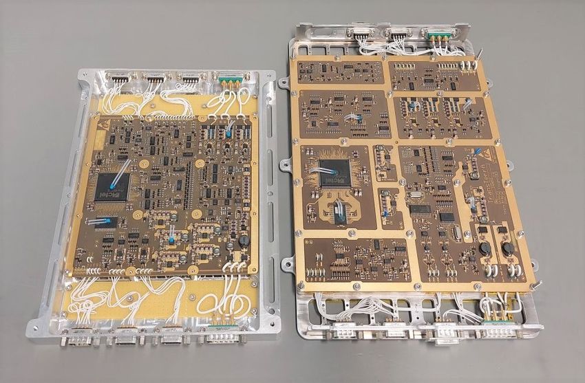
Table 1. Overview of robotic joints for space applications, [2], [3], [4], [5], [6]
 Parameter        ROKVISS                  IDD (azimuth)         LARAD (middle)          CAESAR Joint               DFKI-X Joint
 duration         2005-2011                s. 2004               -                       up 10y                     12 - 14 month
 usage            ISS                      MER, Mars             ISS, LEO                LEO, GEO, Moon             TET-X, LEO
 status           finished                 in use                EM                      EM under dev.              EM
 motor            BLDC-TD                  DC                    BLDC                    BLDC-TD                    BLDC-TD
 gear             HD                       PG, HD                PG, WG, HD              HD                         HD
 reduction        160:1                    8137:1                no ind.                 no ind.                    100:1
 torque           40 Nm                    45 Nm                 129 Nm                  80 Nm                      22 Nm
 speed            15 rpm                   0,86 rpm              0,95 rpm                1,66                       26 rpm
 mass             2480 g                   460 g                 no ind.                 no ind.                    850 g
 Top              -20◦ to +30◦             -70◦ bis +45◦         k. A.                   -20◦ to 60◦                -20◦ bis +80◦
 controlled       FPGA                     k. A.                 MCU                     FPGA/DSP                   FPGA
 sensors          TOR, POS, CUR,           MAS, ENC, POS,        AS, ENC, POS, CUR,      PS, TOR, CUR, TEM,         CUR, TEM, ENC, AS
                  TEM ENC                  TEM                   TOR, TEM, ACC           ENC
 ACC:             acceleration sensor                            POS:                    output position sensor
 AS:              angle limitation                               TEM:                    temperature sensor
 CUR:             current                                        TD:                     torque drive
 ENC:             motor encoder, incremental                     TOR:                    torque output sensor
 HD:              harmonic drive                                 DSP                     digital signal processor
 MAS:             mechanical stops                               MCU                     micro controller
 PG:              planetary gearbox                              WG                      worm gear

The Lightweight Advanced Robotic Arm (LARAD) was
developed on behalf of the United Kingdom Space
Agency (UKSA) and in collaboration with a consortium
of UK companies and manufactured at Airbus Defence &
Space. The goal of the LARAD is to expand the capabil-
ities and availability of long-range manipulators for in-
orbit applications or planetary exploration. In that case,
the manipulator will also provide a testbed for tooling tri-
als. The newly developed manipulator can lift a 6 kg pay-
load under 1 g of gravitational acceleration or use a 4 kg                   (a) CAESAR Joint [2]                   (b) Joint of the Larad
tool with 15 N reaction force. As a technology demon-                                                               Arm [3]
strator, the latest technologies are used to manufacture the
arm and joints (Fig. 2(b)).                                             Figure 2. Current joints under development for space
                                                                        robotics applications
With a similar purpose, the Compliant Assistance and
Exploration SpAce Robot (CAESAR) was developed by
DLR. Based on the RockViss joint, it represents a fur-
                                                                        mission requirements, as given in [9], have been used
ther development, whereby the mechanical set-up was
                                                                        to define a reference mission. The key mission param-
only slightly changed. In terms of the position where the
                                                                        eters and top-level requirements are according to a LEO
electronics are integrated, the arm represents a compro-
                                                                        mission with an altitude of 450 km, up to 850 km and a
mise, as they are not housed within the joint as in Rock-
                                                                        duration of 12-14 month. The rating for operations of
Viss, but in a separate box at the base of the manipulator.
                                                                        the DFKI-X joint is derived from a sinusoidal load case
The Joint (Fig. 2(a)) is designed for a variety of on-orbit
                                                                        which occurs on the shoulder joint of the DFKI’s walking
services and a multi-purpose use like assembly, mainte-
                                                                        robot SpaceClimber while climbing within a 30◦ inclined
nance, repair, and debris removal receptive to LEO- and
                                                                        slope and evaluated during experiments [10]. However,
GEO-stationary missions [2].
                                                                        levels for radiation, thermal and vibration loads were
                                                                        tested also with higher values, as described in Sec. 7, for
Background DFKI X-Joint: The overall design and the                     benchmark reasons and to pay regards to unknown lunch
integrated approach of the DFKI-X joint, as described in                configurations and potential longer mission durations for
[1] is based on the iStruct joint, initially developed for the          further applications.
Charlie robot [7], and is the further advancement of the
SpaceClimber joint, developed in 2007 [8]. Until today
a wide variety of modular robotic joints has been devel-                3.   MODEL PHILOSOPHY
oped for terrestrial and underwater robotic applications
at DFKI RIC, spanning a range of nominal torque from                    Based on experiences that the DFKI already has in previ-
2.5 Nm up to 1000 Nm.                                                   ous described robotic applications, a hybrid philosophy,
                                                                        shown in Fig. 3 was chosen. The electronics is identified
For development and qualification purposes, the TET-X                   as critical element, hence, several tests were carried out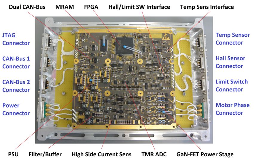
3 4 5
2
1
9
10
11
6 7 8
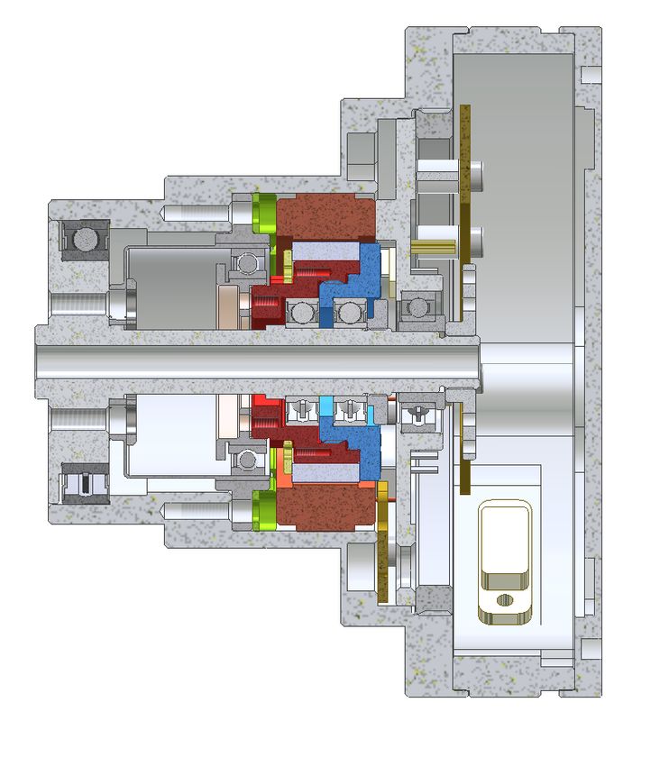
Figure 4. CAD representation of DFKI-X Motor-Gear
Unit, 1: output shaft, 2: aluminium housing, 3: Har-
Figure 3. Model philosophy for reaching TLR 5 monic Drive CPL-14-100-SP gearbox, 4: BLDC motor:
Robodrive ILM 5008, 5: rotor unit with target ring (blue),
6,8 SBN four point bearing pair in O-arrangement, 7:
in advance for testing the suitability of available COTS SBN precision bearings for rotor in O-arrangement, 9:
components, as e.g. against radiation [1]. In addition, this OMH3075B hall-sensors, 10: nut for adjustable output-
made it possible to specifically investigate variants of cir- bearing pre stress and targets for electric limit sensors,
cuits preliminary and select them for the EQM. Towards 11: cable routing and connectors
the envisaged integration to a compact joint, mechanical
and thermal behavior of the electronic assembly with the
motor unit could already be tested by using an STM. The vacuum and vibration loads tests. The EQM was used to
model philosophy represents a reasonable compromise in perform all critical environmental and functional tests on
terms of development time, risks and costs. On the fol- qualification level with appropriate margins.
lowing, the models and corresponding test results are fur-
ther explained.
4. MOTOR UNIT
Development Model (DM): Two boards of the joint
electronics in breadboard layout for the pre-development Figure 4 shows the schematic design of the DFKI-X joint.
of software and for preliminary tests of the COTS compo- The detailed construction is described in [1]. Derived
nents were built. On the mechanical side, a demonstrator from the DM, only minor changes were made to the EM
was built with respect to form and function of the final and EQM. Regarding the overall stiffness, bearings were
design. Both served as first model for planned radiation replaced with stronger ones of the same series and the
and functional testing, parameter estimation, integration shaft with its output side screw holes was strengthened to
model, and for analysis and inspection. The knowledge endure higher mechanical loads. Most obvious is the ex-
gained from the setup and initial tests was used primarily tension for routing the sensor cables to ECSS standards
to improve subsequent models and was incorporated into and for adding micro d-sub connectors. To set electrical
the development process. limits and for calibration of the joints position, two hall
sensors as for motor commutation were used (see Fig.
Engineering Model (EM): The EM corresponds in 4). Targets integrated in the shafts end nut give feedback
form and function to the design of the EQM. The only about the output position. The setups allows a resolu-
exception is the gearbox, which is not certified for space tion of 0.12◦ which is enough for the reference robotic
use. The integration processes of the joints could be use-case. The maximum outer diameter of 99 mm was
tested and practiced on the EM. The STM of the electron- chosen under considerations regarding integration of the
ics can also be used for this purpose and the integration electronics into a joint module. Compared to the DM of
for the EQM can be tested. the joint, this increased the overall dimension, but it also
underlines the need of downsizing approaches for elec-
tronics, described in Sec. 5, for future developments.
Engineering Qualification Model (EQM): The EQM
represents the final stage of the DFKI-X joint and was
built up twice with one spare electronic PCB. That allows 5. ELECTRONICS
to perform extended tests like life-time and testing close
to the expected maximum performance with high risk of The EQM joint electronics as shown in Fig. 5 is based
destroying a unit. Additionally, it also allows conclusions on selected COTS components with adjustments to the
to be drawn about differences that could be caused by design level of the DM, described in [1]. Figure 6 shows
manufacturing and integration. For investigating the in- the schematic design of the functional building blocks.
tegration of the electronics directly at the joint, its repre- Without changing the basic performance parameters, the
sented by an STM, which was also used during thermal following changes were made at design level.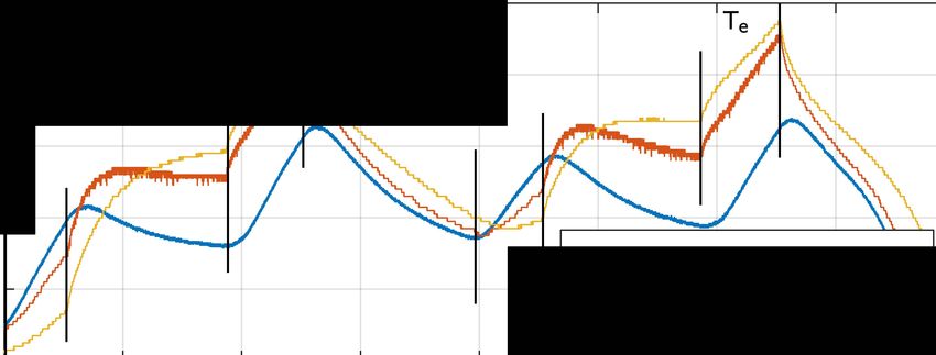
Figure 5. EQM of the highly integrated DFKI-X elec-
tronic unit
To prevent an undefined state for the GaN-FET power
stage, the FPGA PWM signals to drive the motor phase Figure 6. Electronic functional blocks
were mirrored to a second FPGA I/O Bank and merged
by discrete logic for realizing a self-testing of “Single
event Upsets” at the FPGA I/O Banks. So non float- future developments. Figure 7 shoes the assignment of
ing signal could reach the GaN-FET driver ICs such that the functional building blocks and the principle design of
the power stage always has been in a well-known mode. the electronics STM.
Also, the FPGA I/O Banks are coupled via some single
I/Os to find out, if a single event upset happened. In ad- Pad 2 Pad 3
T5 T6
dition, a triple redundant oscillator with FPGA voter was hall- and position-
sensor unit
R22 R32
selfmonitoring
R3 = 100Ω, 1W
added after output level degradation was observed at the
bending are
unit
R21 T1 R31 T2
200Ω
200Ω
COTS oscillator under radiation during preliminary test- ADC's 200Ω 200Ω PSU
ing of the DM. Due to budget constraints, no different (2,5 g)
(2,5 g)
R2 = 100Ω, 1W
types of oscillators could be tested with respect to func-
tionality under radiation. Leading to the decision to add bending area bending area
three different COTS oscillators in parallel with differ- T7
T4 Pad 1 Pad 4
GaN-FeT- stages
ent technologies (default CMOS, PECL/LVCMOS and R1 = 100Ω, 1W R41
R4 = 100Ω, 1W
200Ω FPGA
MEMS type) with a software voter. 3 x power
measuring
R11 T0 R12
T3
bridges 200Ω 200Ω peripherie
R42
For keeping the assembly more compact, the two differ- connectors 1 2 3 4 5 6 7 200Ω
communication
(5 g)
ent CAN-Bus protocol controller were removed and re- (6,5 g)
placed by FPGA software. Only the transceivers and their botton side
8 9 10 11 12 13 14
(additional mass: 16,5 g)
top side
ESD/EMC protection circuitry were used, which saved to motor Micro sub-D (mass glue: 1 g)
components. Respective reducing the size of the board,
the placement was realized double sided and more com- Figure 7. Functional blocks assignments
pact in comparison to the DM, shown in Fig. 1. It was
possible to reduce the PCB size from 250x200 mm (DM) To realize the fusion of electronics and mechanics with
to 160x160 mm (EQM) without changing performance minimal installation space, a solution for a 3 dimen-
parameters. sional arrangement of the electronics was searched for.
Different mechanical concepts and methods for connect-
5.1. Structure and Thermal Modelling of a Folded ing the divided boards to the DFKI-X joint have been
and Integrated Joint Electronic investigated. Mechanical stiffness, thermal coupling,
lightweight design aspects and the routing capabilities
The development of the current electronics for the DFKI- have been driving factors for the selection. During analy-
X joint (Fig. 5) has so far been carried out separately sis it turned out, that the amount of connectors would not
at the layout level from the integration into the DFKI-X allow to use plugs or cable connections because of space
joint. However, the goal is as described above a further restrictions. A semi-flex PCB design was chosen, which
minimization of the dimensional area of the electronics provides a homogeneous layer structure and a solid man-
for a sufficient integration to a compact unit. For that, the ufacturing while cost remains low. Disadvantages such
STM replicates the electronics closely in terms of mass as the bending radius of 5 mm are compensated by the
and the thermal properties. As a result, testing during fact that this distance is required anyway for higher elec-
the verification process (Sec. 7) will provide data that trical parts. The area of the current electronics, which
will allow conclusions to be drawn about the integrability corresponds to 256 cm2 , could be accommodated on the
of the electronics into the joint and serve as a basis for flex-PCB with a diameter of 95 mm, by four boards. The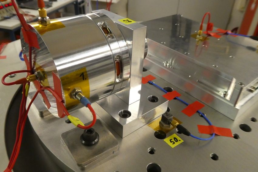
Figure 9. Basic sequenz of key tests for the EQM

 Figure 8. Fully integrated EQM of the Joint with STM

mechanical structure was designed with respect to a max-
imum thermal load of 4 W at heating by a gradient of 8 K        Figure 10. Load curve used for the joint in following
to the center of the PCB compared to the housing. These         tests, depending on rotation speed
values were estimated at the first radiation loads tests with
the DM of the electronics, considering the degeneration
due to the lifetime. The housing was designed with a wall       7.     TESTS
thickness of 1.5 mm aluminium. Due to its round shape,
it has high stiffness in all spatial directions. The low-       The test strategy was chosen to meet the required refer-
est natural frequency analyzed was 515.25 Hz. Electrical        ence mission parameters as well as to determine the per-
parts are replicated by additional masses for the vibration     formance and maximum duration of the components. The
loads tests. The electrical power losses could be simu-         test sequence, shown in Fig. 9, was preceded by vari-
lated by resistors while temperatures were measured for         ous pre-tests [1]. Each test is divided into separate runs
each board near the mounting side and in the center to get      and levels, between each environmental test the joint was
a detailed look into the thermal behavior during thermal        subjected to functional tests. Destructive designed tests,
vacuum testing. The assembled STM with the DFKI-X               such as the radiation test, were performed with additional
joint is shown in Fig. 8 and was used during mechanical         space models. Within the environmental tests, the load
and thermal-vacuum tests, as described in Sec. 7.               curve shown in Fig. 10 was used. In spite no lifetime
                                                                tests was performed, the EQM of the joint itself reached
                                                                during the campaign more then 40,000 revolutions. [12]
6.   SOFTWARE DESIGN
                                                                7.1.     Vibration Loads
To reduce development time and cost the software to
drive and test the DFKI-X joint was build up on the soft-       The test setup for the vibration loads test is shown in Fig.
ware used in almost all motors at the DFKI RIC as al-           11. The sensors measure the resulting acceleration at tests
ready described in [1]. This software uses the NDLCom           specimens. Measuring points were: At the rear of the
protocol [11] which facilitates a flexible low-level com-       STM, at the output of the shaft and on the top of the elec-
munication with minimal overhead and is therefore suited        tronics housing in the center. The positions were chosen
for the use within the DFKI-X joint.                            to monitor the parts with the expected highest deflection
                                                                during test and/or critical parts where low deflection is
As mentioned in Sec. 5 the CAN-Bus controllers were             required, as the output shaft.
removed in the redesign of the electronics and a minimal
CAN-Protocol stack was implemented within the FPGA.             The parameters for qualification level are shown in Ta-
To obtain a reliable clock signal a TRM module was im-          ble 2. Since the test parameters for payloads below 10 kg
plemented which tries to recognize degradation of the os-       are not specified for each launcher and they differ sig-
cillators. A second TRM module was used to verify the           nificantly from the requirements for heavier payloads,
output signals of the different ADCs. Also an error han-        the test parameters from the Space Shuttle [13] (ran-
dling was implemented which uses the self-monitoring            dom Vibration 01) and the calculation formula according
capabilities of the electronics as well as normal error de-     to ECSS-E-10-03A (random Vibration 02) were chosen.
tection as it is used in other joints (e.g. temperature and     The sinusoidal run corresponds to the values for payloads
current limits or plausibility tests of input signals).         below 50 kg according to the requirements of ECSS-E-
                                                                10-03A. In general, due to the low mass of the joint, the
For testing, a widget to enable and disable the different       selected test parameters for the vibration level, especially
function blocks of the electronics was implemented to           those according to ECSS-E-10-03A, can be classified as
check them seperately during the runs.                          very high and above the requirements of the TET-X ref-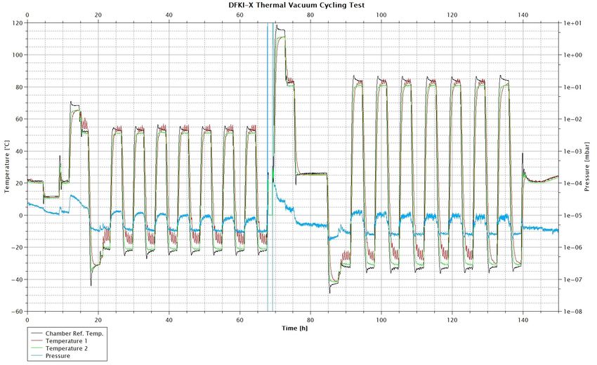
Table 3. Parameters for thermal vacuum testing, Values
                                                                 in brackets: second run, TNO: temperature non operat-
                                                                 ing , TSU: temperature at switch ON, TOP: temperature
                                                                 operational
                                                                   ambient                       qualification    experimental
                                                                   TNO-max                       65               110 ◦ C
                                                                   TSU-max                       60               85 ◦ C
                                                                   TOP-max                       50               80 ◦ C
                                                                   TNO-min                       -30              -40 ◦ C
                                                                   TSU-min                       -25              -35 ◦ C
Figure 11. Mounting of the DFKI-X Joint with STM and               TOP min                       -20              -30 ◦ C
electronic on shaker                                               hold duration                 2h               2h
                                                                   stability                     1 K/h            1 K/h
                                                                   vacuum                        10−5 hPa         10−5 hPa
                 Table 2. Vibration loads
                                                                   joint                                    parameters
  run         parameters         intensity         duration
                                                                   Load                                     3-15 Nm
  resonance   20 - 2000 Hz       0,5 g             2 oct per
                                                                   T-On/Off                                10/30 min
  search                                           min
                                                                   rotation speed, (cycle 1)              20 to 200 ◦ /s
                                                   =
                                                   b 200 s         rotation speed, (cycle 2-8)       10 to 80 ◦ /s (reduced)
  sine        5 - 21 Hz          11 mm             2 oct per       STM-On                                  0,8/1,6 W
  vibration   21 - 60 Hz         20 g              min
              60 - 100 Hz        6g                =
                                                   b 200 s
  random      20 - 50 Hz / +3    0,025 g2 /Hz at   2 min per
  vibration   dB/oct             20 Hz             axes
  01          50 - 600 Hz        0,15 g2 /Hz
              600 - 2000 Hz /    0,025 g2 /Hz at
              -3 dB/oct          2000 Hz
                                 (12,9 Grms )
  random      20 - 100 Hz / +3   0,19 g2 /Hz at    2 min per
  vibration   dB/oct             20 Hz             axes
  02          100 - 300 Hz       0,525 g2 /Hz
              300 - 2000 Hz /    0,11 g2 /Hz at
              -5 dB/oct          2000 Hz
                                 (18,2 Grms )

erence mission [14]. For the verification, this means that       Figure 12. Overview thermal cycle, red: values for TET-
flying with any available luncher would be in principle          X Mission, blue: experimental values
possible. However, the lunch configuration has always to
be considered specially.
                                                                 vals. This allowed to adjust the motors temperature to the
All runs passed successfully. Notable was, that the mo-          chambers temperature during idle periods. The second
tors noise and current consumption decreased signifi-            cycle was performed under continuous operation at 35%
cantly after first vibration tests performed. It may be          of the maximum power. The test passed successfulexcept
due to a reduction of stress within the pre-stressed bear-       for an error in low-voltage measurement in software. Ta-
ings. However, no noticeable backlash was observed at            ble 3 sum up the test parameters. In Fig. 12 the whole
the joint after all vibration tests finished. Nevertheless,      test sequence is shown.
the effect should be further investigated for future devel-
opments to ensure that no negative impact is verifiable.         During the tests, the STM was used for further inves-
The lowest eigenfrequency measured at the STM was at             tigation of electronics thermal behavior (Sec: 5.1) dur-
449.5 Hz. The value agrees well with analysis results,           ing thermal cycling tests. Figure 13 shows the detailed
since the influence of the three measurement sensors is          course of the heating curves from the joint and the STM
not negligible to the light structure. The analysis was          during operation in the warm phase of the first thermal
repeated including the measurement sensors and cables            cycle. The power-up phases, during which the motors
mass with a deviation of less than 10%.                          velocity profile was active, are labeled with TE . The
                                                                 blue line shows the motors temperature, measured at the
                                                                 stator. The red line (STM-T0) corresponds to the tem-
7.2.    Thermal Vacuum and Cycling                               perature sensor in the center at the motor-side at PAD 1
                                                                 (c.f. Fig. 7). The yellow line (STM-T3) corresponds to
For testing under thermal and vacuum conditions, the             the temperature in the center of the uppermost PAD 4.
joint was operated repetitively. In the first cycle, the joint   The chosen locations and plotted values were selected
was operated under short-time duty at 30-minute inter-           based on the most critical behavior. The diagram be-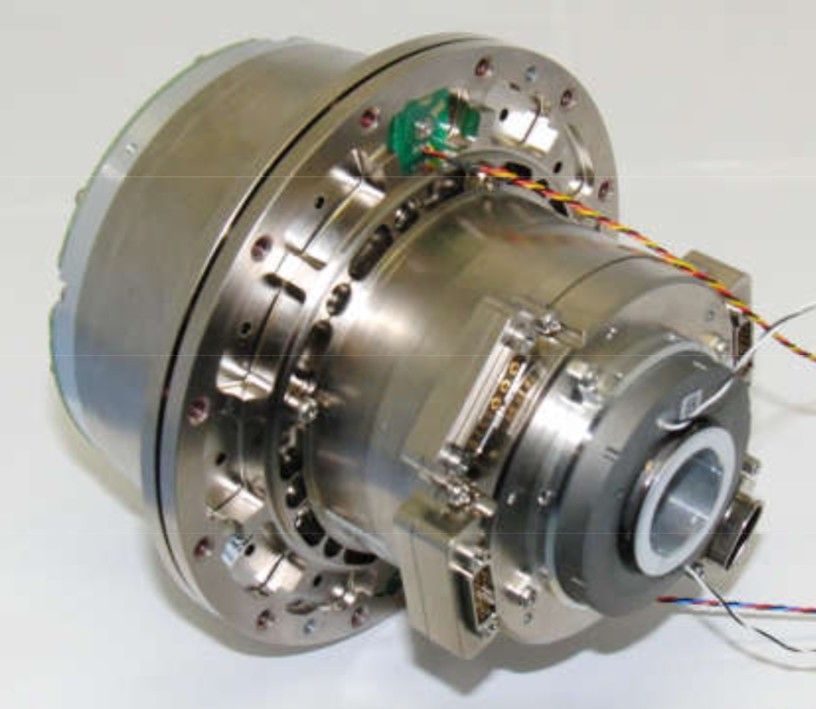
Extraction of thermal cycling test - hot phase
60
,........,58
Table 5. Parameters at the radiation final test, Shielding
3 mm Al, NR: neutron radiation at 14 MeV no shielding
::i 56 Te
Te Run Rate Total dose Res.
�54
--Motor-T0 (Stator/Lid) NR 01 0,34*1010 N 1,74 1010 N P/F
1- 52 --STM-T0 (Center/bottom)
cm−2 h−1 cm−2
--STM-T3 (Center/top)
so�-�--�--�--�--�-�--�-� TID 01 0,36 krad/h 5 krad P
18:15 18:30 18:45 19:00 19:15 19:30 19:45 20:00 20:15 TID 02 0,36 krad/h 10 krad P
2 1 1 1 1 1 1 1
TID 03 0,36 krad/h 15 krad P
Annealing - 24h -
- - TID 04 0,36 krad/h 20 krad P
1.5
� TID 05 0,36 krad/h 45 krad F
- -
L.. 1
0.5 - -
J -- Thermal output - STM After a PCB update, as specified in Sec.5, final testing
0
18·
1
18: 1
1
5
1 1
J 11 1 1
:1 according to ESCC 22900 with the final EQM were per-
formed. For TID testing a lower dose rate was chosen
Figure 13. Temperature of the DFKI-X Joint and selected and an additional annealing after the 15 krad step was in-
sensors of the STM during testing at warm phase. Below: cluded. Table 5 summarized the performed runs during
STMs peak power, congruent with motor is running the TID tests. During all test runs the joint was operated
under short term operation (10 min on / 20 min off) while
a maximum power of 80 W was retrieved at maximum.
low shows the corresponding power profile of the STM.
It can be seen, that the maximum deviation of the tem- During neutron radiation testing, triggering of various
perature curves from the STM and the motor in this ex- voltage protectors were observed. However, resetting per
periment was 2.3 K, which is very much within a feasible software led into continuing the run without noticeable
range. The maximum total temperature was 59◦ C. Since failures of the boards voltages and performances. After
the current electronics for the DFKI-X joint are designed transfer to TID test chamber a restart of the board was
for a temperature range of -30◦ C to +80◦ C, it can be as- not possible and needed to be replaced. During TID tests
sumed that electronics with the same shape and physical no significant current increase on the logic power supply
properties as the STM are feasible, according the given was observed. The PC to board communication failed
requirements to reference mission and parameters above. once during test period between 15 krad and 20 krad, but
tests could be continued after a soft reset. During the 20
to 40 krad step the board communication was interrupted
7.3. Radiation
while log data was still transmitted and FPGA ID query
via JTAG was still possible. However, reloaded failed be-
The radiation tests were split into separate pretesting with cause of probably defective internal voltage converter in
the DM as described in [1] and the final tests with the the FPGAs VPump.
EQM. Both tests were set up as potentially destructive
and were performed until the maximum achievable limit.
While first tests served to classify the DM electronics and 7.4. EMC
to see which functional blocks are most sensitive, second
tests performed according to ESCC 22900 to reach the EMC testing for the DFKI-X joint was performed in
10 krad level described below. Table 4 showing the pa- accordance with requirements for ECSS-E-ST-20-07C.
rameters for the first tests runs, passed successfully af- Despite precautions, the test regarding cable bound
ter all required mission key parameters for a 14 month EMC have not been passed an it was figured out that
850 km LEO reference mission, and showed good per- some points have to be focused on for further develop-
formance for COTS components. The last run was ended ments. Besides improvements on electronic hardware
while motor an log-data still running, but failed when try- side, which means basically a better shielding of sensors
ing to reconnect after switching off the joint. and cables.
An identified problem is based on the use of GaN-FETs
Table 4. Parameters at the radiation pre-test, Shielding 3 and there switching speed. Currently a PWM speed of
mm Al, NR: neutron radiation at 14 MeV no shielding about 30 kHz (time-base 33µs) is used but the used GaN-
Run Rate Total dose Res. FETs would change their state in less than 10 ns which
TID 01 0,345 krad/h 2,7 krad P causes for the joint some EMC trouble in range of 2-
NR 01 0,233*1010 N 0,43 1010 N P
4 MHz with slightly more than 50 dbµA common mode
cm−2 h−1 cm−2
NR 02 0,233*1010 N 1,21 1010 N P
noise at the motor phases, although a snubber network
cm−2 h−1 cm−2 and freewheeling diodes were used next to the GaN-
TID 01 0,345 krad/h 5.0 krad P FETs. To reduce this disturbance, an output filter (like
TID 02 0,345 krad/h 9.9 krad P an L-C filter) right after the GaN-FET power stage, a
TID 03 1,068 krad/h 16,9 krad P shielded housing and shielded motor phase cables are re-
TID 04 1,068 krad/h 32,8 krad F quired. To minimize the physical output filter size, an in-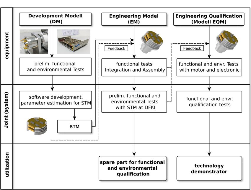
crease of the 30 kHz PWM to about 100-200 kHz and a si-         REFERENCES
nus commutation instead of a block commutation would
be advisable.                                                    [1] R. Sonsalla et al. DFKI-X: A Novel, Compact and Highly Inte-
                                                                     grated Robotics Joint for Space Applications. In Proc. of ESMATS
                                                                     2017: 17th European Space Mechanisms and Tribology Sympo-
                                                                     sium, Hatfield, England, September 2017. VDE.
8.   CONCLUSION AND OUTLOOK
                                                                 [2] A. Beyer et al. Caesar: Space robotics technology for assem-
                                                                     bly, maintenance, and repair. In 69th International Astronautical
The DFKI-X robotic joint, as presented in this paper, rep-           Congress (IAC), Oktober 2018.
resents a highly integrated joint module for robotic appli-      [3] E. Allouisa et al. Larad – architecture and implementaion of a
cations in space. A series of functional and environmen-             lightweight advanced robotic arm demonstrator for future space
tal tests have been performed with very promising results.           and planetary applications. In 14th Symposium on Advanced
The first iteration of miniaturization of the joint electron-        Space Technologies in Robotics and Automation, June 2017.
ics as well as tests with the STM have shown how a possi-        [4] E. T. Baumgartner et al. The Mars Exploration Rover instrument
ble design of compact control electronics can be realized            positioning system. In Proc. of the 2005 IEEE Aerospace Confer-
mechanically and thermally in the future.                            ence, pages 1–19, March 2005.
                                                                 [5] A. Wedler et al. Robotic components for space rokviss and dex-
Using COTS components has been beneficial for inte-                  hand. In Proc. of the International Conference on Robotics and
                                                                     Automation (ICRA), May 2011.
grated functions due to the fact, that more advanced com-
ponents and ICs are available than traditional space com-        [6] A. Wedler et al. DLR’s dynamic actuator modules for robotic
ponents. The used P-FET based over current protection                space applications. In Proc. of the 41st Aerospace Mechanisms
                                                                     Symp., Mai 2012.
circuit in a very small footprint is such a positive ex-
ample. Also, fully automotive qualified GaN-FETs and             [7] D. Kühn et al. System design and testing of the hominid robot
gate drivers have been turned out as excellent and com-              Charlie. Journal of Field Robotics, April 2016.
pact alternative for realizing power circuits. For the next      [8] J. Hilljegerdes et al. Development of an intelligent joint actuator
evaluation steps, critical parts should be early identified          prototype for climbing and walking robots. In Proc. of the 12th
                                                                     Int. Conf. on Climbing and Walking Robots and the Support Tech-
and pre-qualified. Also, COTS parts should be ordered
                                                                     nologies for Mobile Machines (CLAWAR), 2009.
in high quantities and stored to expand the product life
cycle.                                                           [9] W. Moldenhauer et al. TET-X user manual for payloads. Tech-
                                                                     nical Report TET-KTH-UM-003, Kayser-Threde, January 2011.
                                                                     Issu 2.
All required mission key parameters, except some solv-
                                                                [10] S. Bartsch et al.   Development of the six-legged walking
able issues while EMC testing for an up to 14 month
                                                                     and climbing robot SpaceClimber. Journal of Field Robotics,
850 km LEO were observed and passed. Testing on                      29(3):506–532, May/June 2012.
higher levels, such as done for thermal vacuum and ra-
                                                                [11] M. Zenzes et al. NDLCom: Simple protocol for heterogeneous
diation loads, promises a well suited performance of the             embedded communication networks. In Proc. of the Embedded
joint, which could help to bring robotic applications eas-           World Exhibition and Conference, Nürnberg, Germany, February
ier into space. The performed tests with the folded elec-            2016.
tronics STM have shown the feasibility and potential for        [12] N. Mulsow. Beitraege zur Verifizierung des DFKI-X Gelenkes
further miniaturization of joint electronics. However, it            für den Einsatz im Weltraum. master thesis, Universität Bremen,
has to be discussed on system level, to figure out what the          2017.
best approach will be for combining the mechanical and          [13] Special Payloads Division Goddard Space Flight Center. Get
electrical parts of the robotic joint. This aspects along            Away Special, Small Self-Contained Payloads an Experimenter
with a general modularization approach will be further               Handbook, 1 edition, 1985.
investigated in the future. It is envisioned to build up on     [14] W. Moldenhauer. TET-X, User Manual for Payloas. Kayser-
the current breadboard design and the STM pre tests to               Threde GmbH, 2 edition, Januar 2011.
combine all elements into one modular robotics joint unit.
The joint will be part of a standardized robotics toolbox
which is currently under development and is proposed to
be fully qualified for space applications in the near future.

ACKNOWLEDGMENTS

The authors would like to thank the TransTerrA team and
all supporting staff at DFKI Robotics Innovation Cen-
ter Bremen. The work presented is part of the projects
TransTerrA (grant no. 50 RA 1301) and MODKOM
(grant no. 50 RA 2107) which are funded by the German
Space Agency (DLR Agentur) with federal funds of the
Federal Ministry of Economics and Technology in accor-
dance with the parliamentary resolution of the German
Parliament.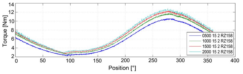
You can also read